Archive for category vanagon
Vanagon – my rotten cluster foil has made me mad
Frank G. did a very nice Passat cluster into vanagon housing conversion and it’s on the blog right here. I don’t know if I will try to follow him but maybe…
Notice the top cluster is in imperial measurements and the gauge faces are all in one piece. Needs overlays. But it’s an electronic speedo so getting the speedo cable to the cluster isn’t an issue ( just need a hall sender gizmo ). The bottom cluster is from a Passat syncro g60. Mechanical speedo which makes things interesting. Note the revs per kilometre number, 80 less than my stock syncro. Oh I don’t know what I’ll do, I bought them in a moment of weakness ( them and a spare alternator).


Vanagon – rude and crude pedal lock
Posted by albell in vanagon, vanagon mods on March 1, 2017
A late Xmas present made from 3/8″ X 1.5″ steel ( 3/8″ is admittedly overkill). Padlock goes through the hole in the removable bar.
The design is a direct copy of one I saw on the net ( I think made by a German vanagon owner). There are a few variations on the pedal lock theme, I chose this one as it seemed to be the simplest.


Vanagon – beating the H4 led subject to death
Posted by albell in vanagon, vanagon mods on February 13, 2017
It’s a provincial holiday here today, Family Day, and what better use of my free time is there but to dick around with the H4 leds some more.
One thing I haven’t mentioned before is my puzzlement with what the data sheet says. It states, and it does not specify if this is for the pair or a single, “input power L/25W H/25W”.

Ok then, let’s see if we can make any sense of that. On low beam only the cup shrouded led elements are powered up. That’s half of the available elements on the bulb. And on high beam all the led elements are powered. So how come the wattage figures remain the same?
I hooked a bulb up to a power source and ammeter. The current draw varied with input voltage. At 14V the current measured 1.20A. At 10V the current measured 1.10A. But curiously, at 11.5V the current measured 1.47A. My power source only goes up to 15.5V, at that setting the current was 1.10A.
That was for high beam, low beam values very similar.
So a couple of things strike me. One is that the current draw had a peak at 11.5V and dropped of on either side of that voltage. Must be something to do with the power regulating circuits in the bulb, I bet it’s obvious to those with a bit of electronic knowledge. The second things is that the current draw was pretty well the same for both high beam and low beam. So that goes a little way in explaining how the spec sheet claims 25w for both high and low beam.
But do my measured values even come close to the spec sheet values? Let’s take the 14V reading, 1.20A.
(1.20A)(14.0V)= 16.8W
That’s a fair bit from 25 isn’t it?
Again it’s not clear if the spec sheet is for one bulb or two. If it’s for two then doubling measured value for one bulb would give 33.6W. Closer to 25W but come on…
At this point I get the feeling that either I’m missing something damned obvious or else the spec sheet is inaccurate.
As I had one of the led bulbs in hand I thought I’d try comparing it to a 55/60W halogen in a couple of 6.5″ e code H4 lamps. These are nice German made Hella lamps, new old stock, unused, meant for the Iltis military vehicle. I thought I’d shine the lamps onto a bit of black card and see what the beam pattern looks like at a very short projection distance.
The lamp(s)

The super sophisticated experimental set up.

Low beam, 55W halogen. Oh I have to add that the batteryused as power source wasn’t at full charge, it’s at 12V. And for some reason the halogen low beam is lass bright than expected. But it’s beam pattern I’m interested in.

Now low beam with the led bulb.

A little different but certainly comparable. More light down low on the led don’t you think?
And now high beam, 60W halogen.

I draw your attention to the defined beam pattern outline, and compare to next, high beam led.

I’d say, and certainly feel free to disagree, that the led beam pattern is slightly less defined. But both quite comparable.
You know it all comes down to the placement of the light emitting elements in the lamp housing. And to how the light disperses from the elements. I think that the led placement is fairly good, but I think (and talking completely without any direct proof) that how the light comes out of the led, how it radiates from the surface mounted elements, differs from how the light emits from a tungsten filament. It’s not an outlandish assertion, the halogen filament is held in space and radiates all around, 360 degrees. The led elements are constrained by being placed on a surface and the best they can do is radiate 360 degrees minus the amount the led back plane interferes ( and that’s assuming that the led elements alone radiate 180 degrees, and I’m not sure that they do).
Ok enough of this for now. I think the thing that will put this exercise to rest will be the side by side comparison with the halogen lights on good friend Simon’s van.
Vanagon – H4 led bulb update
Posted by albell in vanagon, vanagon mods on February 12, 2017
I’ve been trying out the led bulbs since I first posted about them. I still have the same opinion, low beams good, high beams meh. In rain, and in snow, I’m not seeing a much of a drop in the high beam performance though.
I took a little time tonight to take some pics with a 80/100W bulb in right hand side lamp and the led in the left hand side lamp. I couldn’t find a good wall close to home, I apologize for using that corrugated metal structure.
Ok, here we go, first up is both low beams on. Left is led, right is 80W halogen. Notice the halogen has more of the angled kick, better defined. The led not so much and there is a stray beam at a higher angle.

Now it’s low beam left, led, only. You can see more of the angled beam kick now, not masked by the halogen. That stray angled beam shows up better too.

And now low beam right, 80W halogen. Nice beam definition eh?

On to high beams, first is both high beams on. Not really much to say about this except it’s a blast of light.

This is the 100W halogen alone.

And the led high beam. Oh boy that corrugated steel is not making things easy is it?

Just as in the original post about the led bulbs I have to say again that pictures don’t capture the compete picture 🙂
Ok now to a gently sloping downhill dirt road. Same drill, same comparison. You be the judge.


So what do I think? I want to like them, I really do. But I’d give them a 7.5/10. I’d like them to be brighter. And I also have the suspicion that the led element placement that I showed in the original post is not quite right (as compared to the filament position in the halogen bulb). I might take the time to play around with a spare lamp and and bulb, on the bench, and see if some adjustment to the bulb projection into the lamp has any effect.
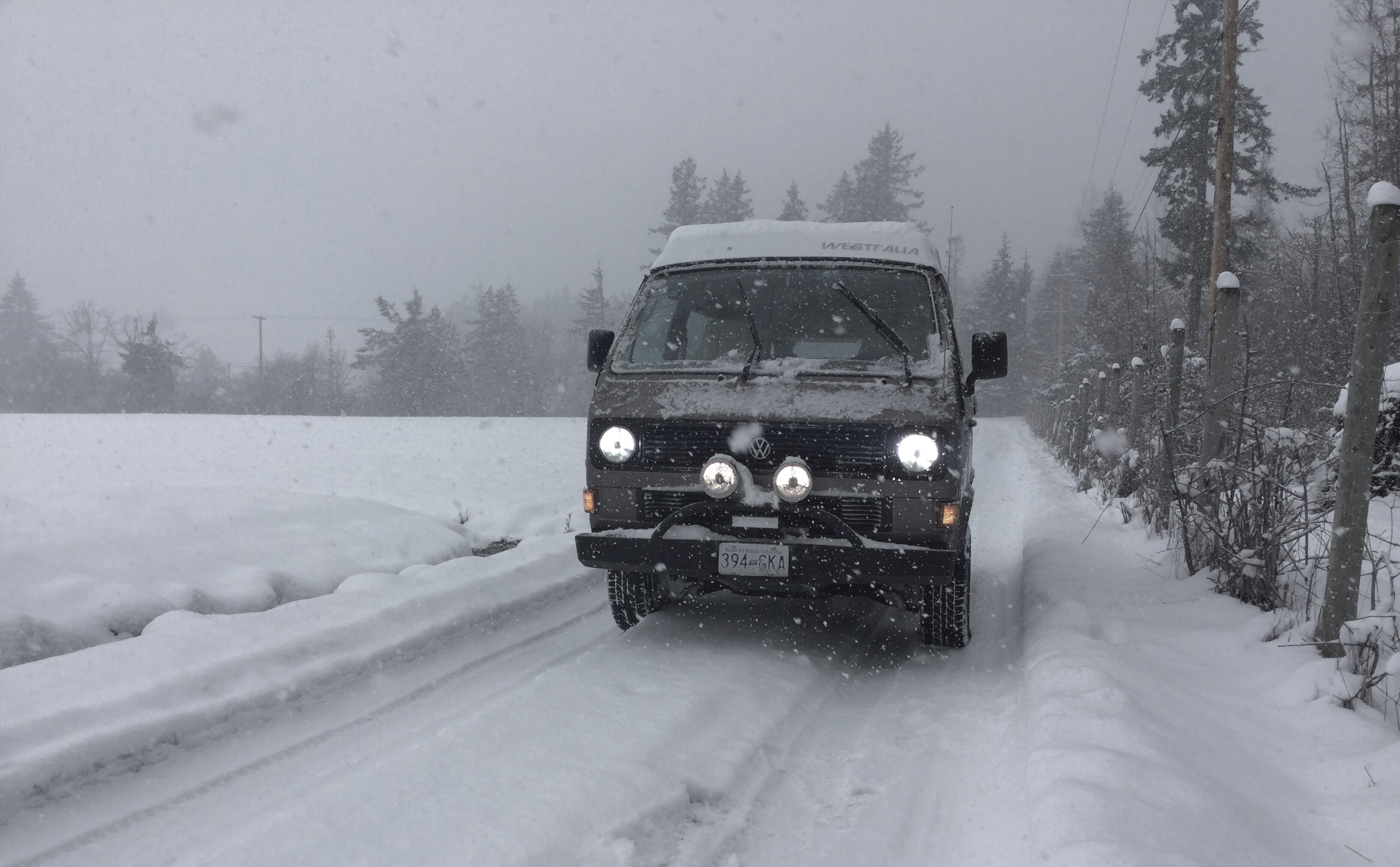
Vanagon – in a little snow
We had a “it used to happen more often but seems to be less now” little dump of snow.
Vanagon – H4 led light bulb experiment
Posted by albell in vanagon, vanagon mods on January 17, 2017
Update, January 17 2017. I need to clarify a couple of things about this experiment. First, the led bulbs were tried in my Hella 7″ e-code (e 4 to be precise) lamps. The lamps are in good shape, no hazing on the lens and the reflectors are in great shape. They do however have stick on impact protection film applied. The beam pattern, specifically the low beam cut off, appears to be very similar whether it’s led or halogen bulb. But yes I should document that, and if I can find a suitable wall close by I will.
Second, I am having a hard time quantifying or even describing clearly my perception that the high beam distance projection seems less with the led bulb. I think you’ll just have to take my opinion on this for what it’s worth.
Oh and one more thing. The radio interference from these bulbs annoys me greatly. I have a fair bit of pwm regulated led interior lighting and have not noticed any interference from those. I have noticed a little interference from my “built into the bumper ” led back up lights, that should have been a warning I guess. Hindsight is so very very clear isn’t it? The interference effect now cautions me with another pwm project I have on the bench. I will test it in the van before going any further.
Ok, before you say anything, I know. I know the arguments about replacing the halogen bulb in H4 lamps with an led unit. And I agree with them. But, I had to try this.
What got me trying was reading a positive report about a Philips led bulb replacement. What was new to me with the Philips was the location of the led elements on the bulb. It mimicked the location of the high and low filaments of the halogen bulb and also had the little shield on the low beam elements similar to what is on the halogen bulb.
I think the Philips led units, and forgive me for not linking to a source, are around Ca$150 a pair. A bit steep for me but then I found what look to be close copies listed on Banggood. And, unlike other led drop-ins, these are passively cooled via a finned heat sink. Others have fans in the heat sink and for some reason I didn’t like that.
So for around Ca$45 bucks I bought a pair, and they arrived on the slow boat last week.

You can see the led element layout in that pic. Just to be clear they are double sided. And you can see the little shield or shade over the distal elements. Just to be pedantic, here it is compared with a halogen bulb.

I didn’t try to do any measurements comparing the led element positions with the halogen filaments but you can see they are approximately in the same location.
Another view of the led bulb.

It doesn’t look like those little shields on each side line up perfectly does it?
Installating in the lamp is a breeze. The three prong adapter ring is a twist fit on the bulb. You remove that and install the ring on the lamp and clip down the wire bail as you would with normal bulb. This pic shows the led bulb with the adapter ring removed.

And adapter ring installed.

And the bulb goes in with a push and twist lock. It didn’t seem like a very tight twist and lock, not pleased with that. Oh, and the bulb can be inserted in two orientations, 180 degrees apart. You have to be careful to get it right, to have the little shields/shades in the same orientation as the original halogen.

And there you go, lamp goes back into the van. I did this during daylight so a comparison picture ain’t that special. Mind you, taking any kind of picture of lighting is more or less folly. The pictures never seem to tell the same story your eyes do. But I did take a picture with one lamp having the led bulb and the other lamp with a 80/100 halogen. Both are on low beam, cam you feel the difference?

Yup, driver’s side has the led. Seems pretty bright eh? And with all high K value leds it makes incandescent lights appear more amber.
And what about when it was dark? Didn’t take any shots of the lights but I did do some driving. The low beams are nice, like the whiter light on the pavement. But the high beams are not so pleasing. As an aside, I bet most of you know this already, the colour value of the light seems to make a big difference in how you perceive the light. On high beams I was underwhelmed by the projection of the light. It’s hard to put in words, and I honestly can’t explain the effect, but the high beams just don’t seem as strong as the 100W halogens. Well, yes, I am comparing them to 100W so I have to add a grain of salt. What is very noticeable is how bright the reflective roadside signs appear under the led light.
Once I got onto truly dark roads the lights appeared to project further. Boy this is hard to explain, all so subjective, but cut me some slack I am trying.
Tonight I lined the van up beside my friends Ducato van. Stock lights on that van and it was raining. Once again I’ll say pictures are really not very good at reproducing the actual lighting as I perceived it but here we go.
First pic is my van with led lights, low beam ( my van is on the right hand side of the driveway in all the pics so there will be a light bias towards the right of the driveway due to the low and right nature of the lamp aiming).

And now low beams from the Ducato. See how amber the halogen appear

And high beams from the Ducato.

And high beams led.

Even though the pics don’t give a true representation of the lights, I think they do show that on high beams the halogens seem to shine further , or at least reflect back from a further distance. But then again it’s not super distinct.
Oh, one thing to note, the sharp cut off on the E code lamps on my van is still maintained with the led bulbs.
But here is the deal breaker. And it shouldn’t have been as much if a surprise as it was. The damn leds create radio interference. It’s only really bad on weak signals, but it’s very annoying. I bet the Philips bulbs do not do this, I bet it’s a result of the cheap price of the units I bought.
So what now? I’ll run them for a while and try to decide if they are worthwhile. I’m not sure of the things I like about them;
low current draw, the quality of the low beam illumination, immediate on/off high/low switching
Is enough to overcome the things I don’t like;
radio interference, long range reach in high beams, no heat on front of lamp to melt ice and snow.
Vanagon – headlight low beam failure
Posted by albell in vanagon, vanagon mods on December 3, 2016
The other day my low beams took a hike, both at the same time. Not the fuses, not the bulbs, not the grounds, not the low beam relay. Power out of the relay but no power at the low beam connector at the lamp.
So what’s up?
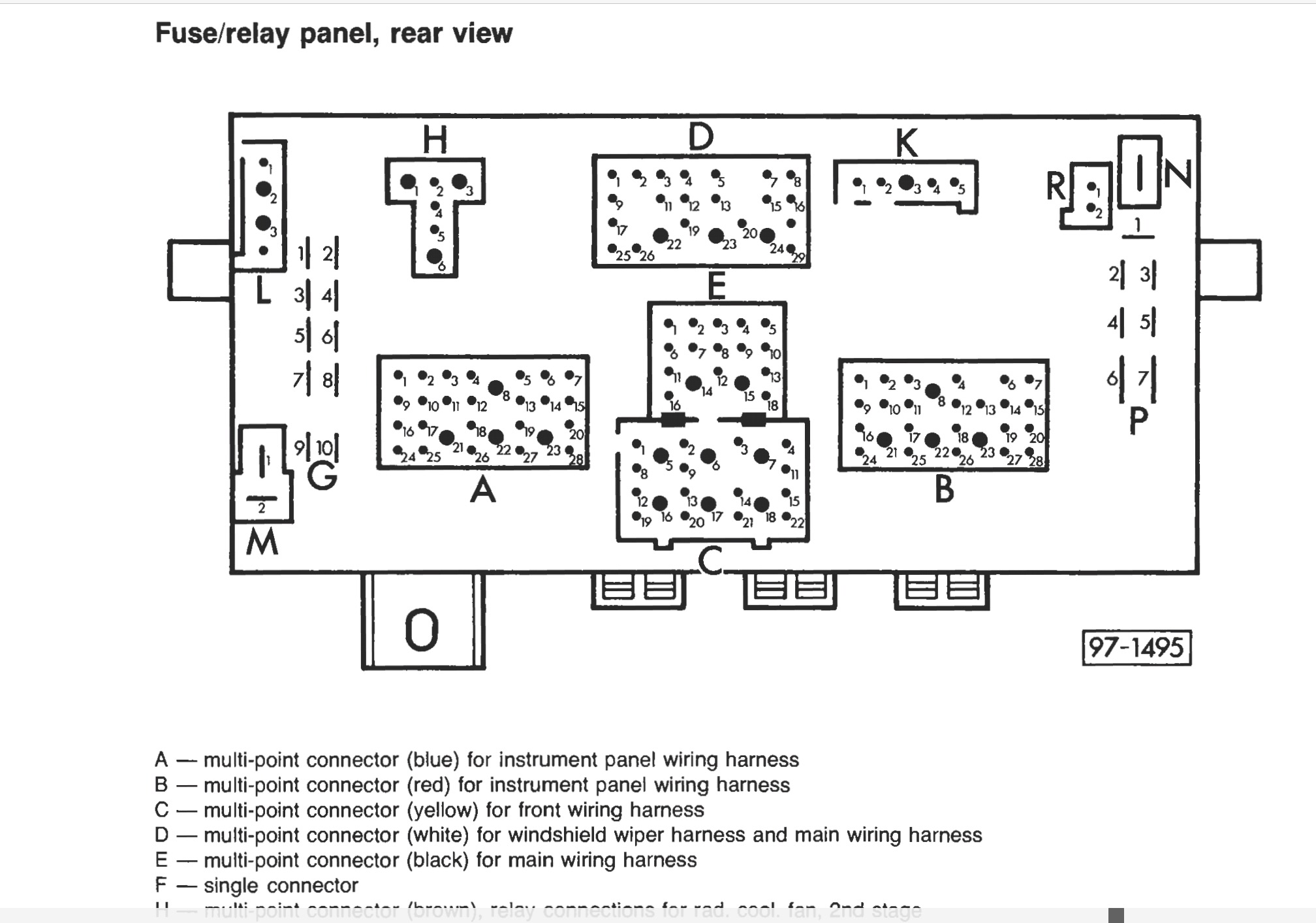
Some background, I have two relays in the headlight system. One for the high beam one for the low beam. Here is the rough schematic of how I wired things

So out of the low beam relay on terminal 87, the current then continues on and back into the fuse panel, pin 21 in the A connector block.

See A21? Turned out this connection was the culprit. Was burned and melted. So much so that I couldn’t get the terminal out of the block to replace. What happened to cause this? I’m thinking it’s was one of those positive feedback things starting with a slightly iffy connection, a little resistance making heat which causes more resistance then more heat etc etc. Ending finally in no continuity. Could I have been over loading the connection with 80W lowbeams? The combined current draw for two 80w lamps would be around 12 amps ( at 13.5 bolts) so I’m not really convinced the terminal couldn’t take that. Edit: sounds like I’m trying to convince myself doesn’t it? Maybe it is too much current for the pin, however the pin carrying the high beam current shows no damage at all, albeit the high beams would be in use less than the low beams. This might all be moot as I have a lower current draw lighting solution that I hope will pan out.
As I couldn’t get the terminal out of the plastic block I cut the wire ( that wire runs directly to the low beam relay) and used the really handy M terminal right close by. The M2 terminal is common to A21, you can see that on the stock wiring diagram above.
Hers the nasty connector ( I tore the plastic clip of the near side) and you see the yellow “jumper wire” to the M2 terminal. It has a bit of black heat shrink on it to give the wire a bit of stiffness, strain relief of a fashion, for the spade terminal.

I really hate working on the back of the fuse panel. And getting the plastic terminal blocks out is a bear. And I always seem to knock some other connection loose with all the tugging and twisting involved in getting the connectors out.
Vanagon – propane skid plate prototype
Posted by albell in vanagon, vanagon mods on December 1, 2016
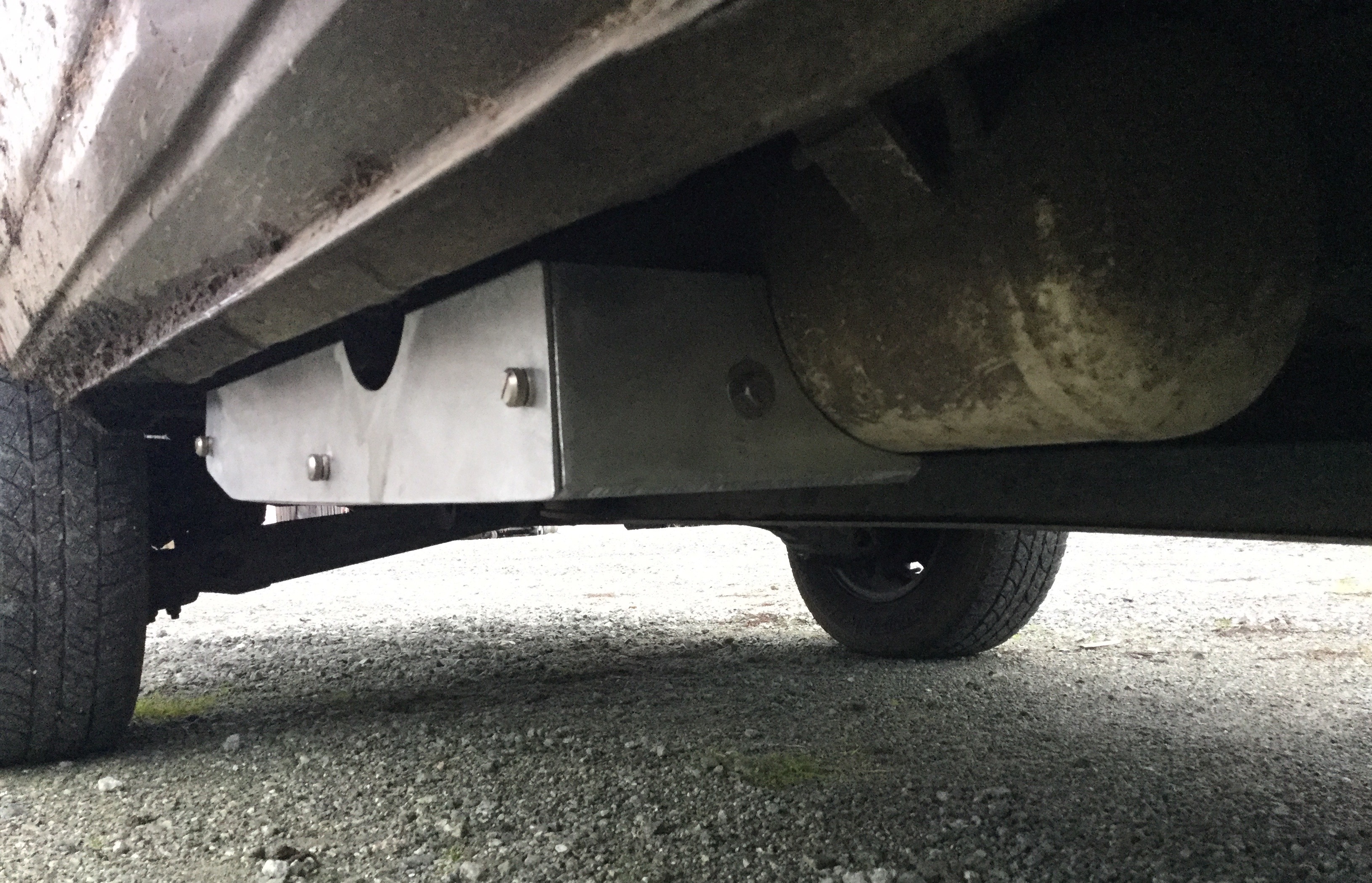
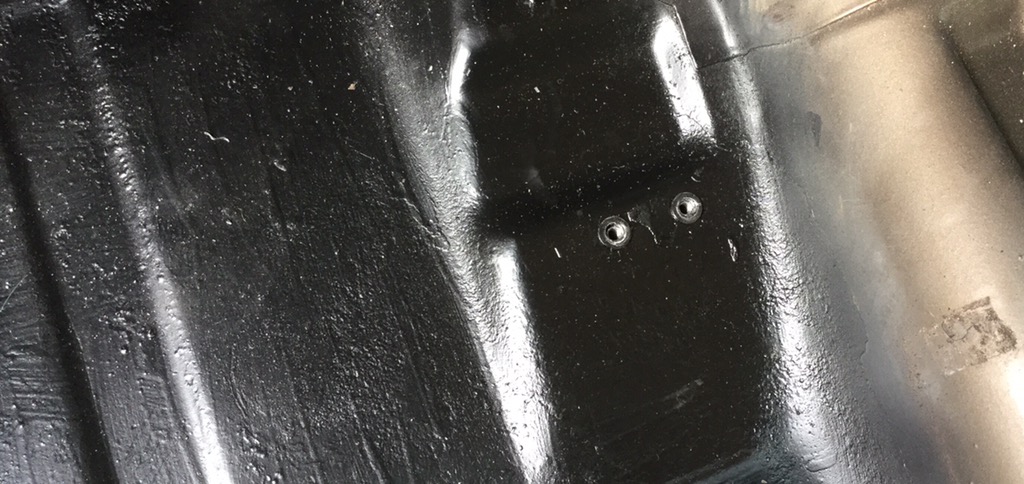
I’ve been mucking around with the notion of better protection of the westy propane tank. I wanted a bit of extra cover to reduce the amount of dirt on the tank fittings and also some protection for the copper lines that lead up into the van. Here are some pics of one prototype. During the making of this one I had a better idea, so another version is in the works.
This one appears to hang lower than the stock skid plate, but in fact it sits a tad higher. I think the unpainted aluminum and the side plate gives the visual effect of sitting lower.
Oh, and I do get a lot of muck thrown up on to the side of the van. Combination of not having my mudflaps on and the 25mm offset of the rims.
I’ll do another post on this skid plate showing it with side plate off and explaining why there is a half moon cut out on side plate.


Jake 2005-2016
Truly was a friend.


Site announcement
Yeah, I’ve been quiet for a while and I’m very much behind in answering comments. I’ll be dealing with that very soon, thanks for your patience.
Main announcement though is that for a few months I’ve been hitting the 3Gb limit of the free wordpress blog plan. I’ve used some very simple jiggery pockery to post pics in the last few blog entries. To be quite honest I baulked at the cost of the upgrade to boost storage to 13Gb ( US$100 per year).
But I broke down and have just now ponied up for the upgrade. One obvious change you’ll notice is no more ads. Well no more ads placed in the blog without my consent.
Well that’s that. Back to regularly scheduled programming soon.
Cheers
Alistair
Simon’s syncro Get-Away-Van
Update: it is for sale, samba ad here…. link
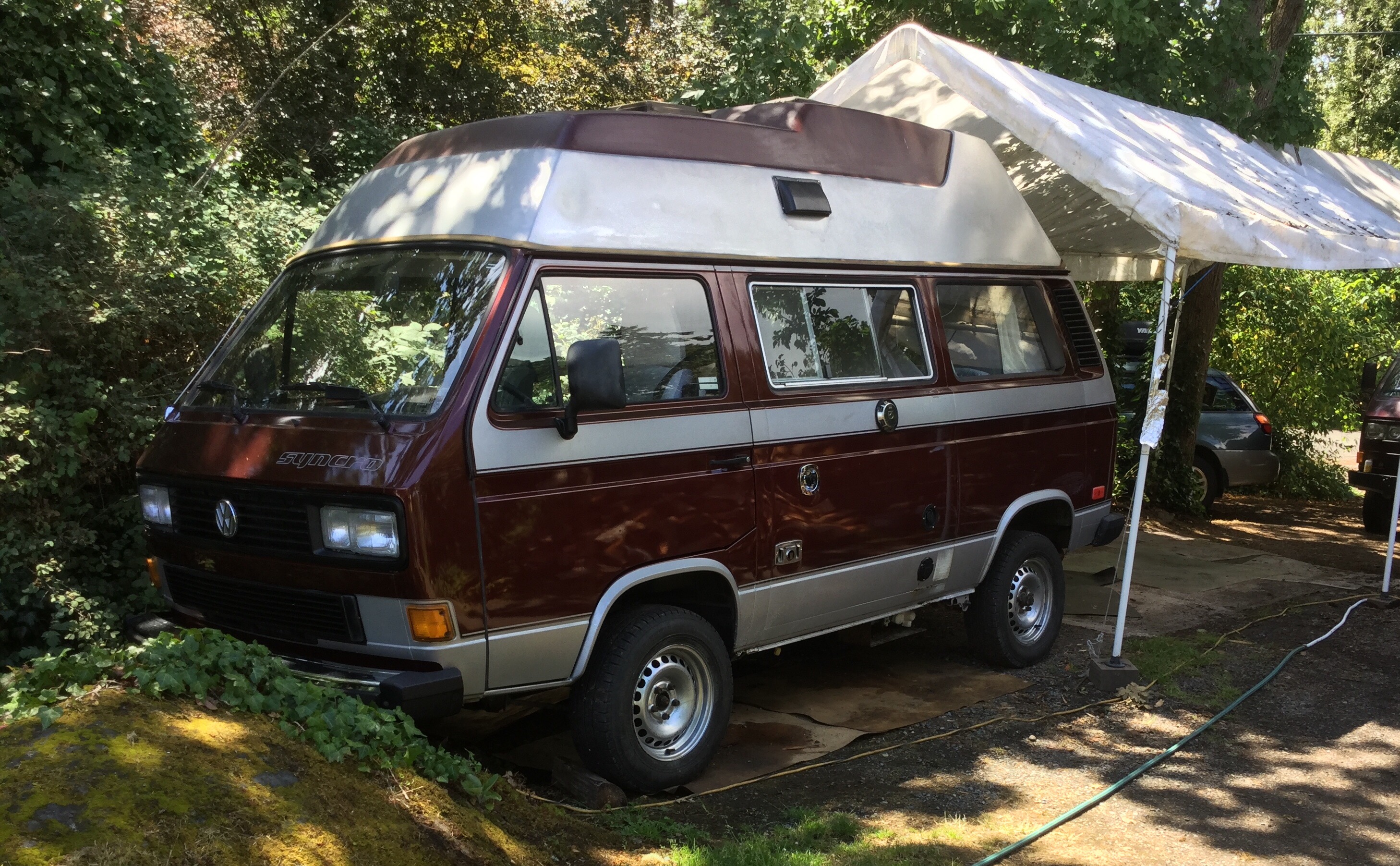
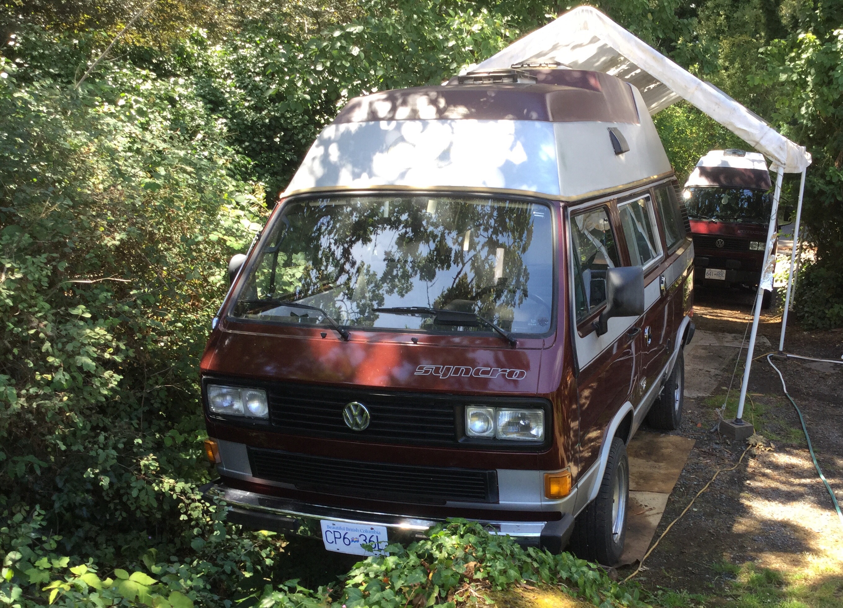
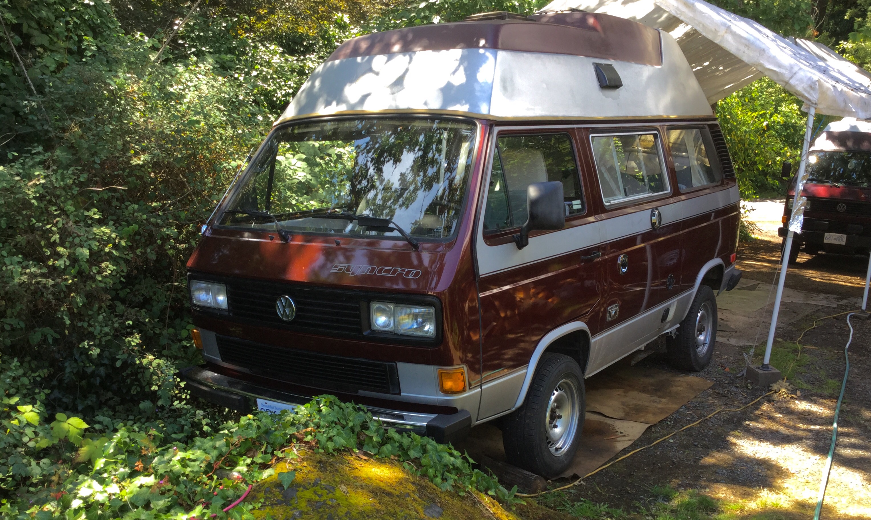
Washed and waxed, and I think up for sale soon. Only 88,000 km (55,000 miles), correction 84,099 km (50,459 miles) body, transmission, engine, all in great shape. I’ve driven it and honestly, it drives very smoothly. I wish my van felt half as good.


Some pics from Simon’s trip
Some of the pics Simon sent from his last trip.
Simon writes:
“We had a great time, through Washington, Montana, Wyoming, Idaho, Oregon, Washington, and home to the island. Altogether maybe 5000 KM? (I wasn’t tracking it). Only a couple of minor issues with the van; my electric locks went funny one day into the trip and so I disconnected them and went manual for the rest of the journey, also my window wash nozzles weren’t spraying, figured out it was a kink in the line at the pump, had a fun time fixing it with a lighter and a golf tee in cold campground in Yellowstone.”


Swellegant table II
Posted by albell in vanagon, vanagon mods on October 22, 2016
So when I made the first Swellegant table gizmo a couple of years ago, blog post here, good friend Simon made sport of my enthusiastic review of it. Turns out he was jealous but it took him until this last summer before admitting it…ha!
Made another, slightly different than the first in some details, and gave it to him. He used it on his recent trip.

Pretty much the same idea as the original, but a little slimmer.


Vanagon – fooling around with gas pedals
Posted by albell in vanagon, vanagon mods on September 5, 2016
Clossic displacement behaviour, I should have been doing other more important things. But I’ve been sort of obsessed by what I thought was sloppy gas pedal feel. You know, the pedal moving sideways. So instead of looking at my pedal to see what’s what, I put it down to the stock design that uses thin plastic to act as a hinge. Spoiler alert, the hinge was partially broken and that caused the sloppy feel.
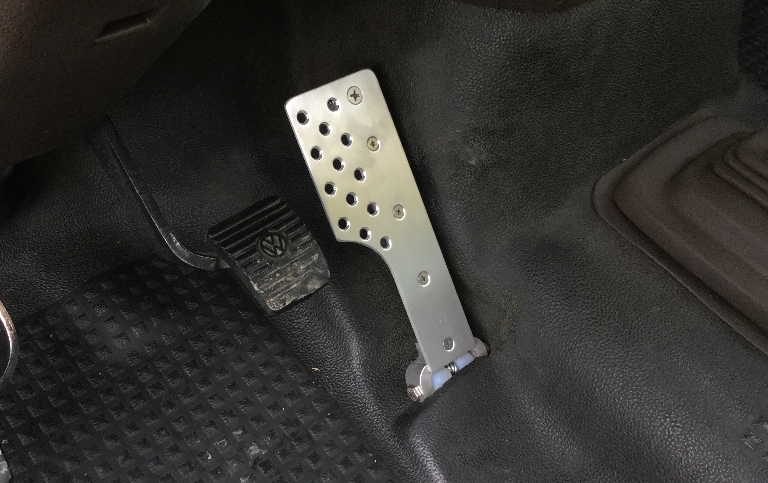
But I went ahead and made a couple of pedals to try out. Here they are, pretty rough but as I said I’m just trying things out. I have a spare stock pedal, shown in the pics, I could have just installed that, why didn’t I?
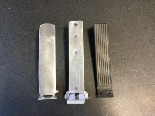

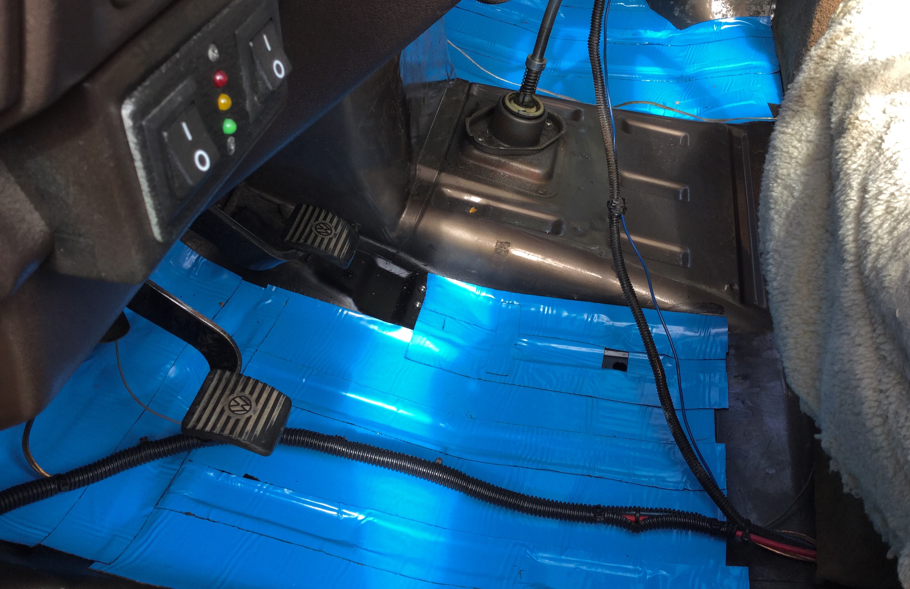
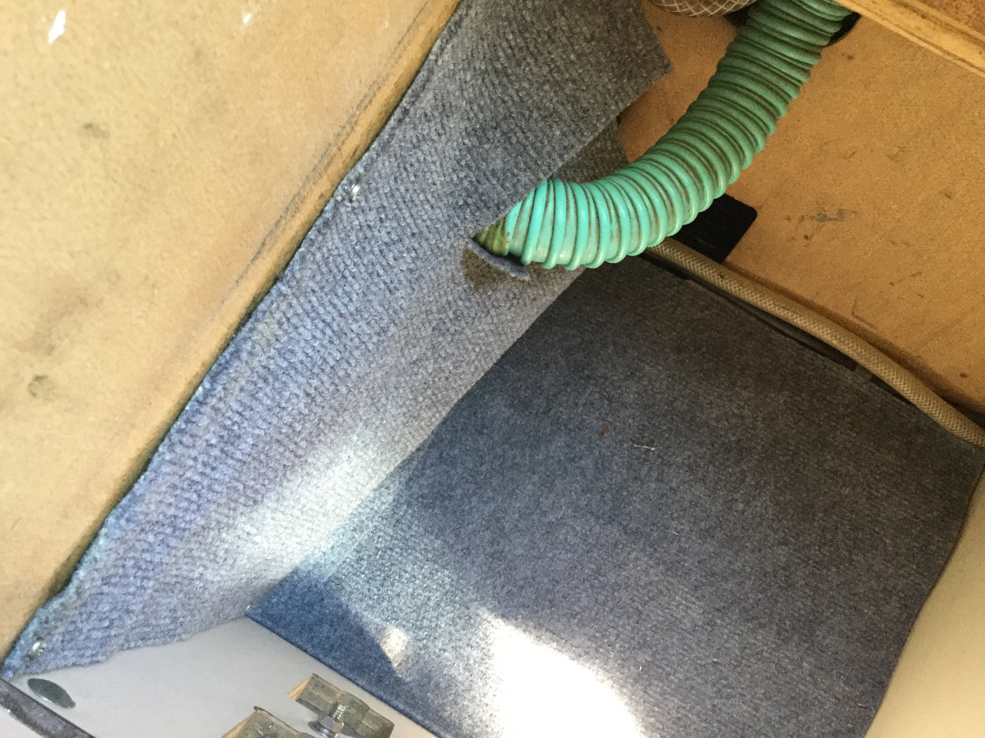
Yes, pretty crude but good enough to try out. I decided on the middle one, has a spring return built in. Thought it might be interesting to see how helping the throttled close will feel. As usual installing the pedal took longer than I thought. You know I have the factory rubber mat laid over the composite foam underlay that came standard with carpet but not with the rubber mat. The rubber mat therefore didn’t fit in quite as nice as it should. It was ok though, but this time when I pulled the underlay out and it broke up even more than before I decided to trash it. There was a bit of surface rust starting in the driver’s side footwell, I wire brushed that and treated it with rust converter then a couple of coats of paint.
The stock pedal was attached to the floor by a couple of pop rivets. I drilled them out and enlarged the holes to take a pair of 10-24 threaded inserts ( I don’t have any metric threaded inserts) .
Test fitting the pedal.

I agree, without that pressed foam underlay will be more road noise coming through the floor. Haven’t figured out completely what to do about that but made a start by sticking down some thin self adhesive asphalt based tape. Yup, tar based not butyl. It’s what I had on hand and I don’t think off gassing or the tape sagging during hot weather will be an issue in this location. Good god but I ramble on.
I have to find a better route for those wires running forward. They haven’t been taped down in place when I took the pic, bout where I did tape them really wasn’t that great. You can feel them under the mat.
Mat back in, pedal installed. The top surface of the pedal is removable. I’m thinking I might make another that is slighlty wider at the top, the extra width on the brake pedal side. It feels ok underfoot and I can feel the resistance of the extra spring. I’ve yet to road test it.

Ok, tried it out on drive to work. Yes it feels firmer, a little more effort to depress it. But I don’t find it a probelm. But what is a problem is that it’s too narrow. It’s approximately the same width as the stock pedal. I know I must be obsessing over this but it bugs me that half my foot is hanging off the side. Do I have some sort of mental issue, i quickly made another pad to replace the narrow one.
Oh yeah, as clunky as it looks, it’s so much better. No really, it is. I mean it, I’m not kidding. It’s the best things since the last thing I thought was the best thing since…
Vanagon – Westy luggage rack mod
Posted by albell in vanagon, vanagon mods on August 24, 2016
Good friend Stephan came across a Westy owner who made a very interesting hinged cover for the luggage rack. You all know that area is a source of wind noise and some owners have put in a flat plate to reduce the turbulence caused by the front edge of the rack. This mod is a bit different and although I’d love to meet the owner and have him argue the reason for the trailing edge design, the entire structure looks very well made.
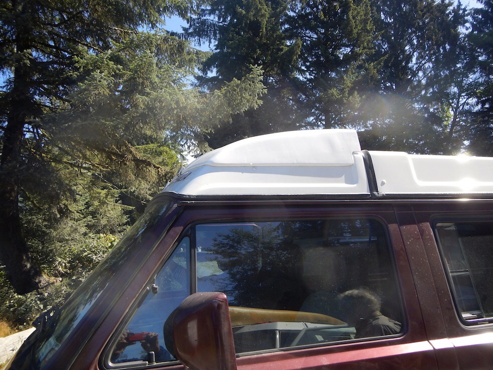

Got a couple more pics. Yes there are latches on the front.

Trip – fogust in the Klanawa valley
Quick report on a four day trip into the Klanawa valley here on Vancouver Island. It’s the main east west valley between Nitinat watershed and the Alberni Inlet. We like this watershed despite it being extensively logged, you don’t meet many other travellers and it has a few special spots. We’ve exported this area a few times, “Klanawa” and the search box on the right will bring up previous posts.
First night was at a small lake. You have no idea how good it felt swimming in that lake after the 3.5 hr hot and dusty drive. Ok it’s hyperbole, but jeez it felt good.


I shouldn’t have been surprised, but the fog from the Pacific was thick the next morning. Dripping wet and chilly. So off we went further west into the fog and found a hill to climb out of it.

About 450 meters elevation we broke through the fog.

We parked on the side of the hill, facing south. By about 2 pm the fog retreated back to the coast. We got too hot, drove down to the Tsocowis river/creek and cooled off. This creek never seems to warm up, its not head numbing cold but it’s not “let’s just float around and enjoy life” warm either.

Than back up the hill and set up for the night.

The road went a bit higher but no better southern view up there. Spot the van?


Yup, the fog/cloud creep back in the evening.
We smelled propane that day, I tried (soapy water) to find the leak. Somewhere at the tank I thought. No luck at detecting it. Ran out of propane during that night. Sheesh. So on Monday we packed up and drove into Bamfield to fill up with propane. Also took the guard off the tank and was able to get a bit of tightening on one fitting. Or maybe it was the spit valve leaking? In any event the leak didn’t re occur. Thought about staying at the campsite at Pacheena Bay, but decided to go back to our spot on the hill after some unsuccessful exploring for the other perfect spot. Do you get the idea we like high places with no one else around?

Yup, fog back in the morning. Actually I forget which morning.

Next day we drove back down into the clouds ( to be honest, the entire valley cleared up around 12 pm). This shot gives you an idea of the maximum grade of most of the roads. I think this is about 18, maybe 20%. Sometimes you find it steeper, and often it’s quite a bit steeper around the switch back corners.

Well that’s it, short report. To be honest it all seems much of a muchness and pretty dull stuff. But the pics don’t do justice at all to how spectactular the area is, and really how much fun it is to explore.


A score!
Some more aluminum honeycomb off cuts , approx 1″ thick. Bits and bobs but useful sizes. Finishing the edges is a pain but I need some suggestions for vanagon specific uses.

Trip – last weekend
Weather great, didn’t get lost, only one thing broke* on the van. The main logging roads were rougher than usual, seems that a lot of the gravel has gone and the bigger rocks underneath are exposed. It’s like driving on very rough cobble.


*a leak on the fresh water line from the new pump to faucet. Manifested itself by a little drip under the sliding door. Didn’t do a field repair, the leak seemed to be in part of line behind the fridge. Wasn’t bad enough to go to all the bother of pulling fridge. But at home, pulled fridge, and I lifted the entire floor (to get it dry). Found the tiny leak at a section of hose that ran adjecent to the fridge combustion chamber. It’s my fault, I secured the line back there with tie downs but too close to that chamber. I’m guessing that the new water pump made enough pressure to weaken the hose that was softened by the heat. Was just a pinhole leak, but still…
Vanagon – Prague syncro high top
My son is traveling and I have been bugging him to find me some T3 action. He was in Beirut and I thought he might get lucky and find one there. Nope, but he came through with this nice syncro high top in Prague.
I very much like the sticker on the front door, “syncro Czech team”.

A quick sketch of Canadian version 🙂

Or the over used syntax…

And one for Simon 🙂

Vanagon – well that’s a ladder idea
Spotted locally by a friend. I don’t know what more to say.
Uodate: I do know what more to say, BenT made the identification, it’s Mike and Geneva of slowcarfasthouse.

Vanagon – Westy pop top lifting bar assembly fix
Posted by albell in vanagon, vanagon mods on July 23, 2016
This post briefly outlines an experimental fix I made to my spare lifting bar assembly. At time of writing, I haven’t swapped it in to the van to give it a good testing, so the jury is still out as to whether the repair works as well as it seems to on the bench.
While I was futzing around doing this repair, Dave commented that I should design something that could be sold as a kit for the Westy owner that doesn’t have access to machine tools, welding, etc. This is a good idea, unfortunately the approach I was taking doesn’t really lend itself to that. But it did give me some hints towards a repair kit.
I think most vanagon Westy owners know by now that eventually the pop top lifting assembly will wear out at the main hinge joint. It’s a poor design, a harsh steel on steel moving contact with no lubrication and insufficient bearing surface. Many other owners have fixed this problem by various means, welding up the worn surface is one example.
Andy, owner of the nice T3 Atlantic, “Wolfgang” (blog linked in list on right side of the page), recently had his lifting assembly re painted. It was his blog post on that and his comments to me that got me off my duff to try this fix.
I have a spare assembly, from my old 82 Westy. It’s galvanized steel, no paint like in the later Westies. The zinc coating has grown the characteristic white fuzz during storage in the barn. Here’s a pic of the hinge that is the problem.
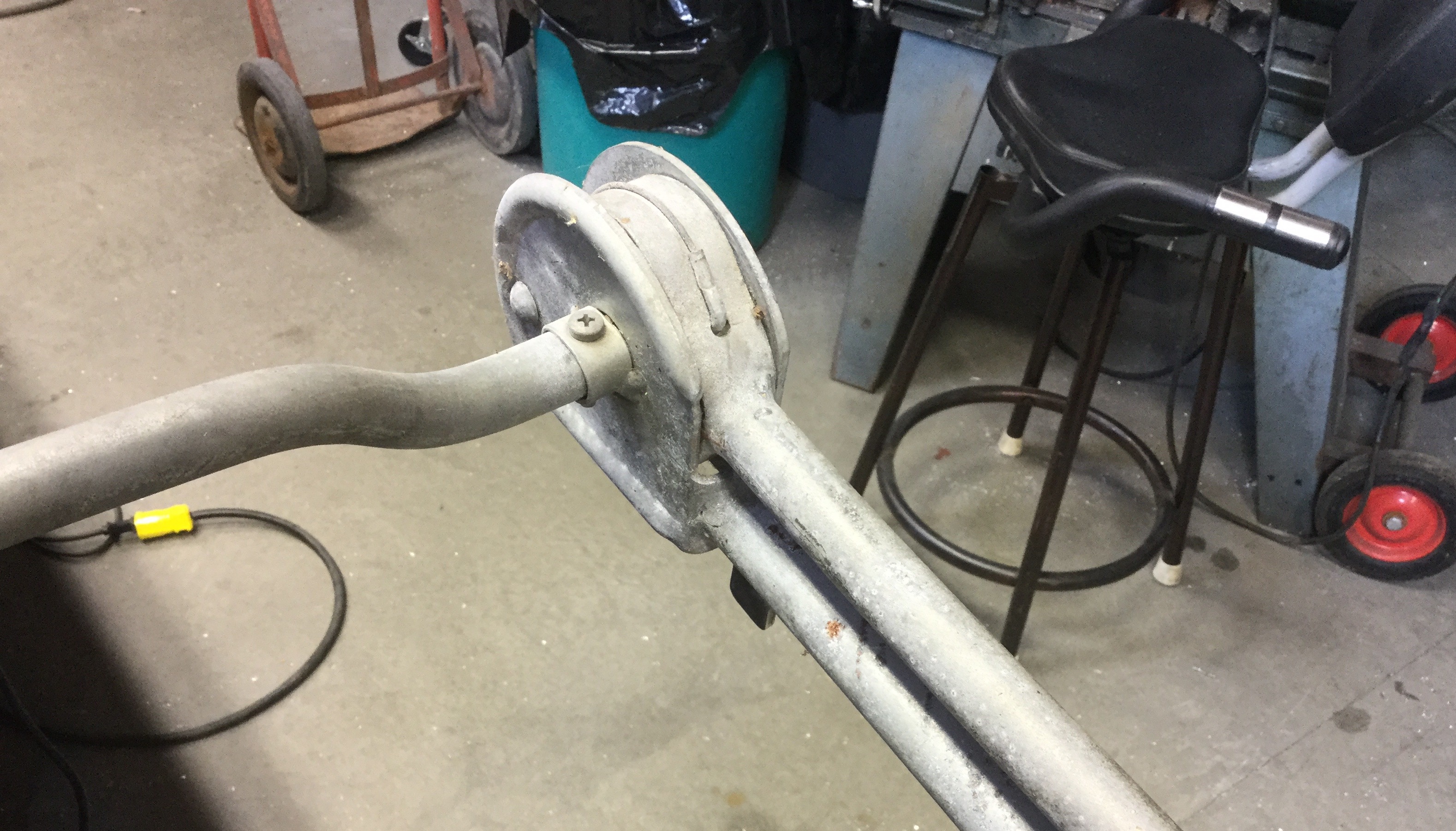
A couple of notes on the hinge. The horizontal bar extends into the hinge through that collar ( with the screw) and near the end it get worn away. There will be a pic of that coming up. The hinge is folded up fully, as it would be when the top is down, and that steel cable you see running up over the round centre section continues down and back into the tube on the bottom where it connects to a spring. Again, more on that later. But as is, the assembly is under tension and wants to straighten out (tubes are tied together out of shot).
Remove the M5 machine screw from each end of the horizontal bar and then pull the bar out of the hinge. Are the ends of that bar worn, Or have you lived a pure life and the bar ends are sound?
One end.

And the other end, even worse.

It’s really easy to take the assembly apart, apart from the annoying spring washers. Clip washers, starlock washers, must be other names for them too. I broke most of mine trying to remove them, but you can find new at the hardware store or auto parts place. When the hinge is relaxed, ie fully extended, and the pin that limits further extension is removed, the end of the spring cable can be detached and pulled out the bottom of the tube. Yes, the foot has been removed from the bottom of the tube. Another pin and annoying clip.

Greasy old spring and cable out.

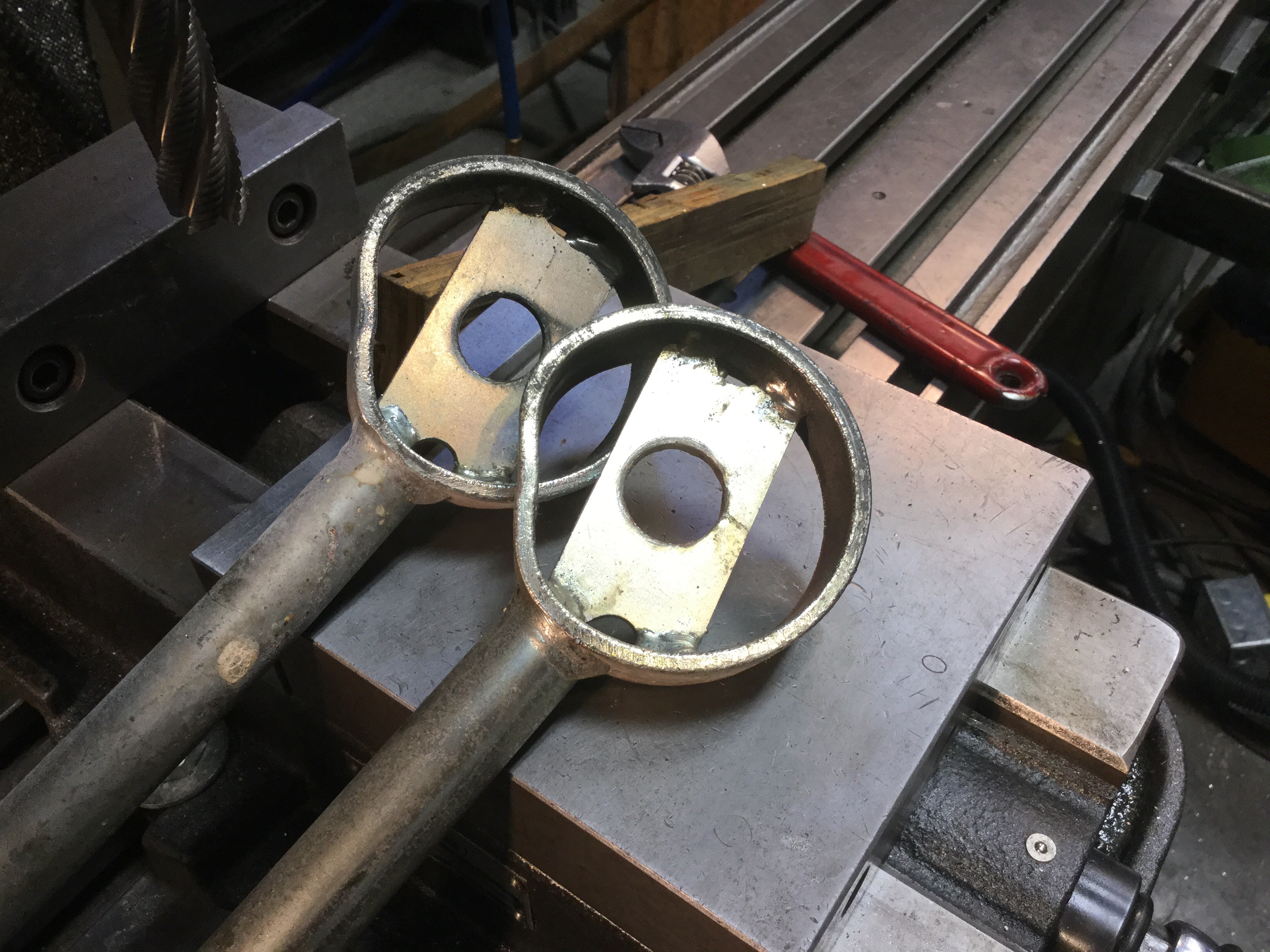
Ok, back to the hinge. Here we have the pair and its the edges on the “not so round anymore ” holes in the flat bar welded in the ring that wear the grooves in the cross bar. I mean really, what the heck were the engineers at Westfalia thinking?
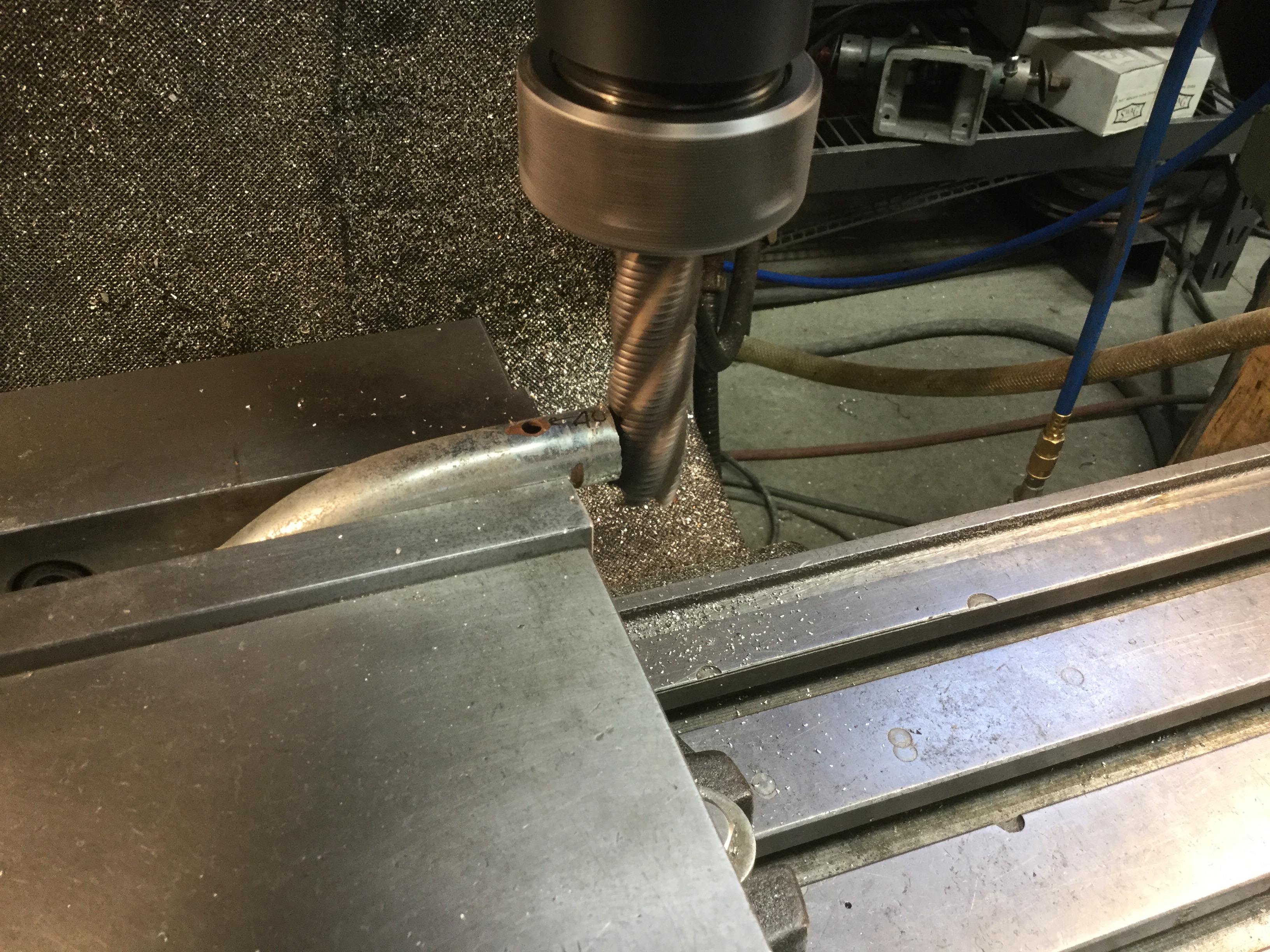
My fix is to bush those holes to create a larger bearing surface. First I had to make the holes more or less round again. 7/8″ endmill was over sized just enough. Truth is, it didn’t complete make round one of the holes, but good enough.
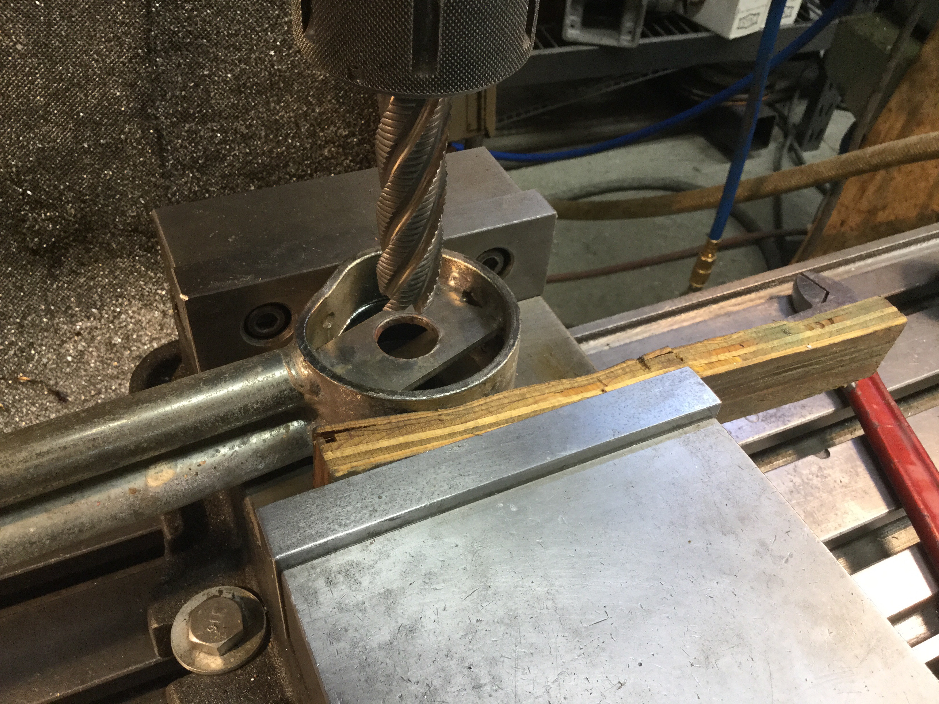
Hard to see the difference, but the holes are now nominally 7/8″ diameter.

Ok, now the bushings. I had a small bit of bronze (or maybe it’s brass) salvaged marine shafting. I had fooled around making flutes on it with the index head. I was learning, wasn’t a great job, had the head offset so the grooves were asymmetric, blah, blah. But there was enough of the stuff to work with.
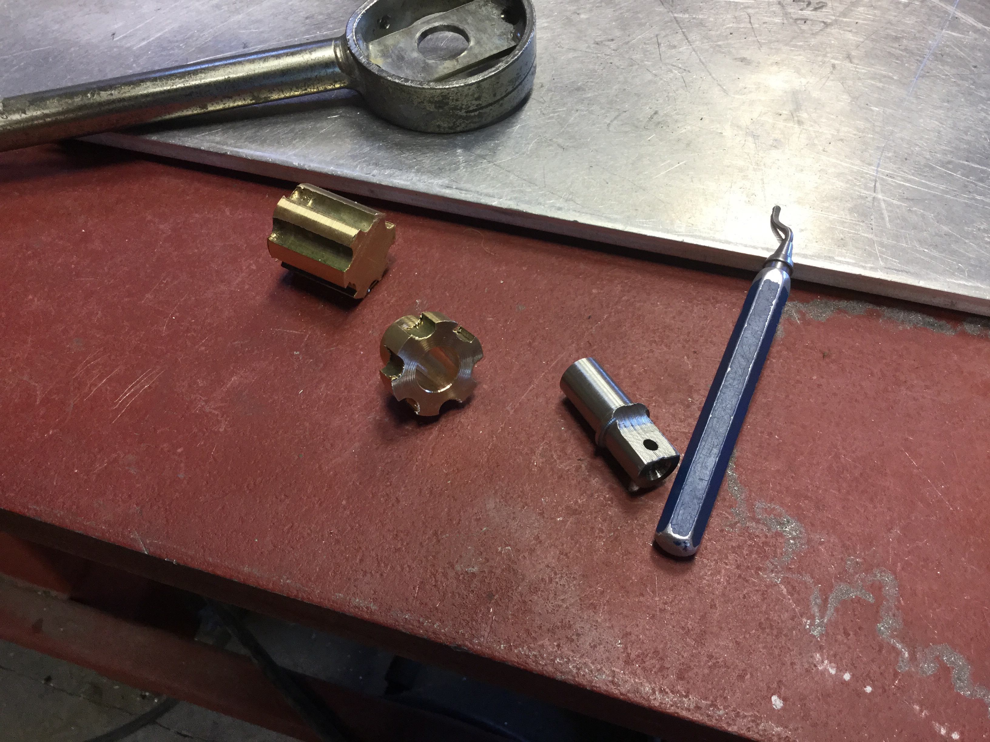
And alongside is the little shaft that will replace the worn end of the cross bar. I reamed the ID of the bushing to 16mm, turned the shaft slightly undersized ( about 15.95mm). The OD of the bushing was left untouched on one end, the other turned down to a press fit for the 7/8″ hole that I milled in that flat bar.
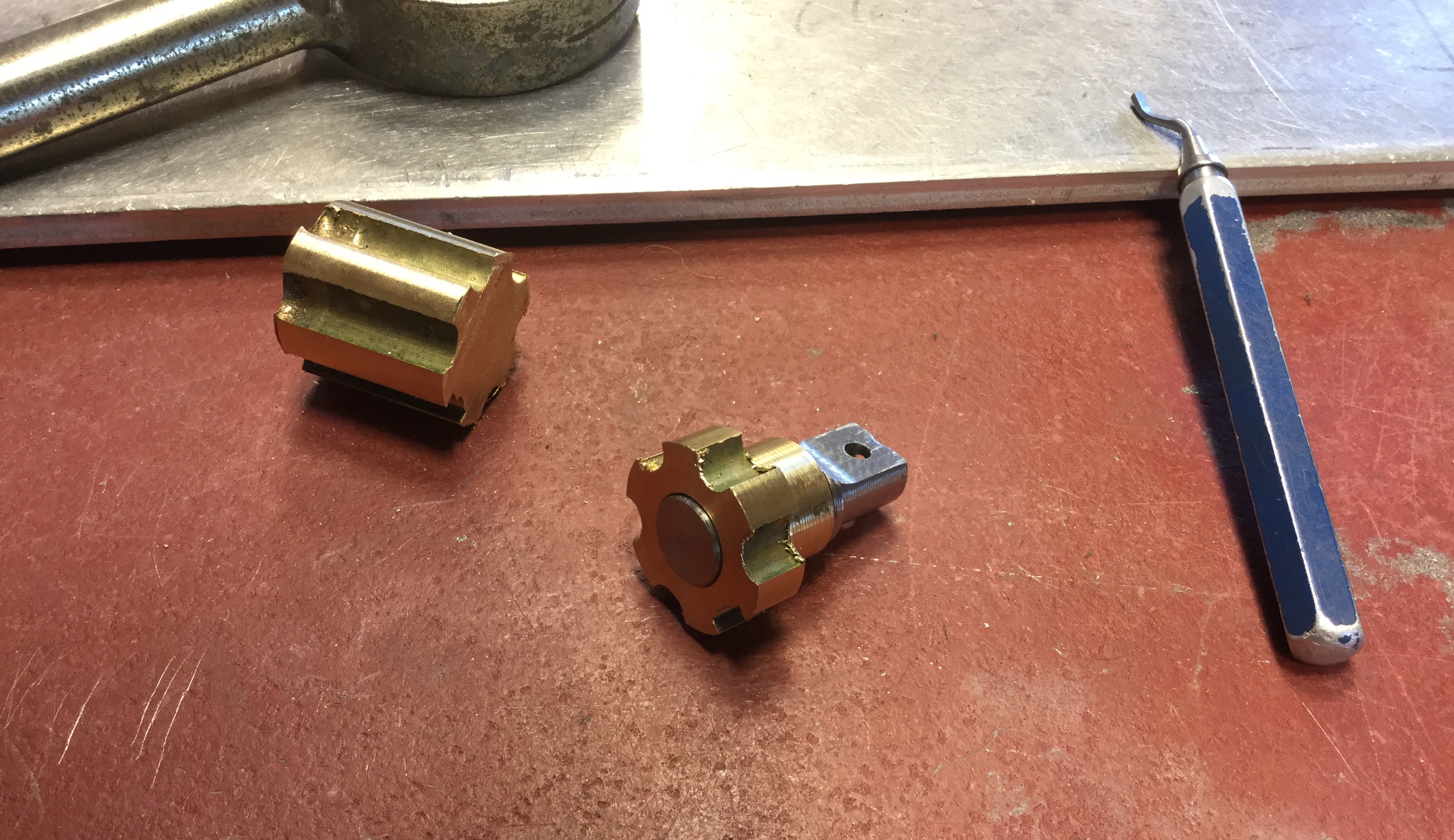
Notice one end of the little shaft has a flat milled on it and a cross hole drilled? That end will fit into the cross bar with the hole lining up with the existing cross bar hole.
I cut off the worn end of the cross bar and milled back square. Still using the 7/8″ roughing end mill. Oh how I love that tool.
So, and excuse the initial so, so I pressed in the bronze bushings. One pressed home with that satisfying grunt that makes one smile, the other… Meh. Combination of pressing into only 1/8″ thick material and the hole not being fully round ( remember I mentioned one hole didn’t fully catch the mill?). I didn’t want the bushing to be able to rotate in the hole, it would then wear away just like the original bar. The answer? 1/8″ roll pin. Holds the bushing nicely in place.
Beside it is the little stainless shaft that is pushed into the end of the cross bar.
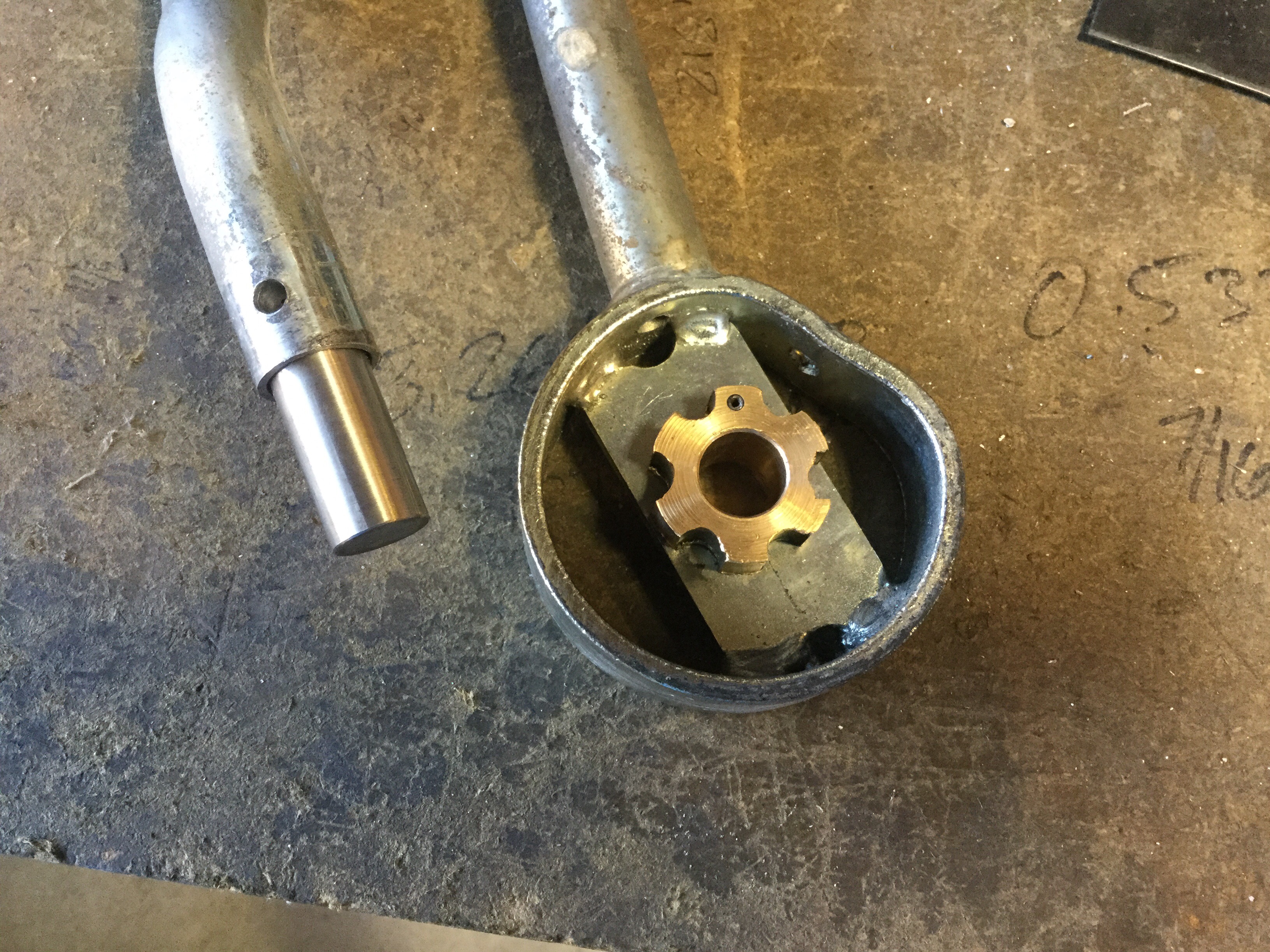
Lubed the shaft up a little with some light oil and put everything back together. The M5 machine screws on the cross bar locates the stainless shaft, it doesn’t move.
Picture taking to forgotten during reassembly, all I can show you is the end of the hinge where you can see the stainless shaft and a hint of the bushing.
But trust me, the hinge action is now nice and smooth. Sometime soon I will install it and see if it lives up to the hype. And, I’ll have a look at the one currently installed in the van with an eye on making some sort of easy DIY kit or procedure.

Vanagon – stereo head unit upgrade
Posted by albell in vanagon, vanagon mods on July 17, 2016
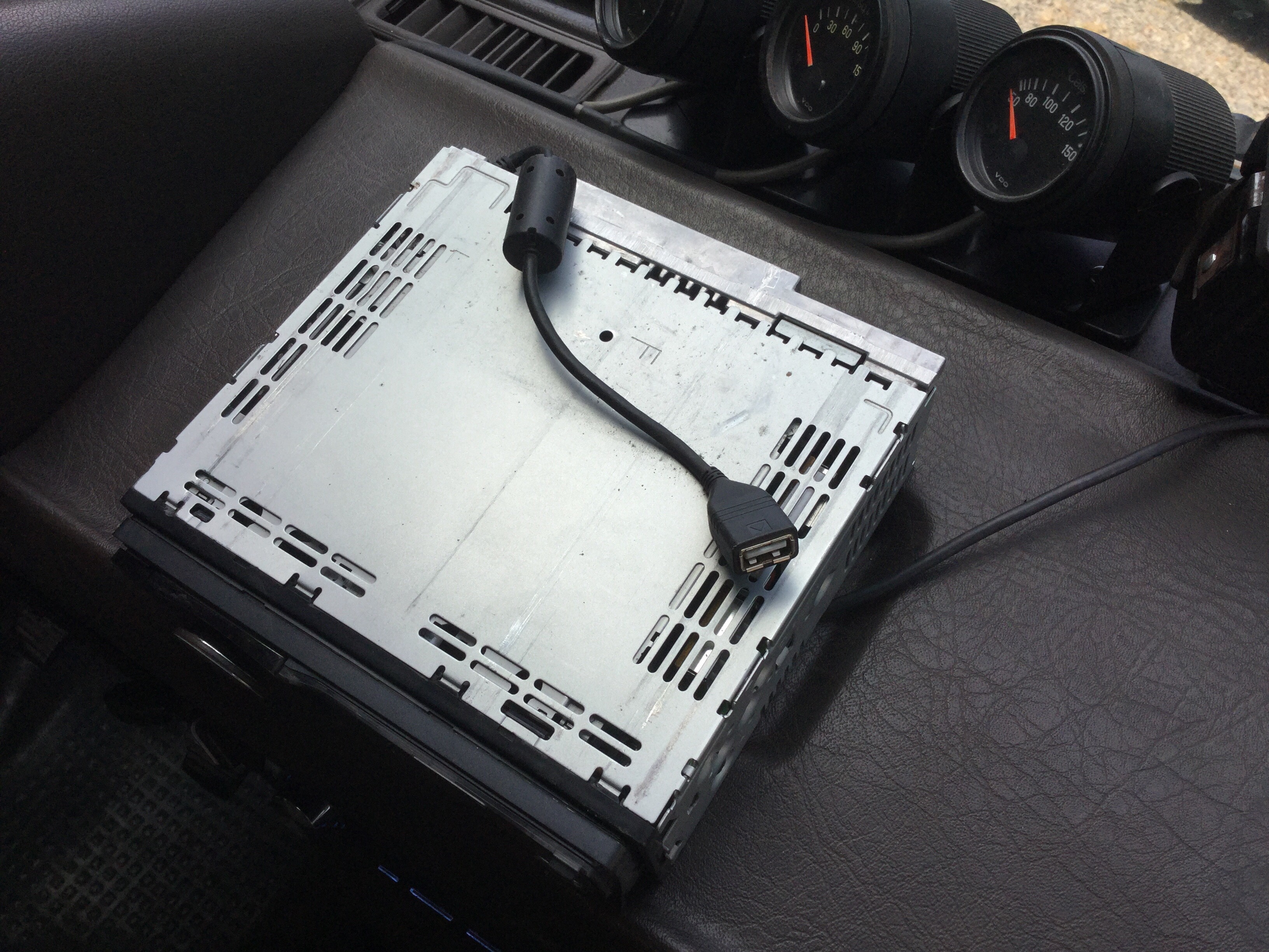
For a few months now I’ve been using a Pioneer MHV-X560BT head unit in the van. It replaced a Pioneer DEH-P5000UB that had worked almost perfectly for 8 years. The older unit did develop a ground loop whine and I posted about that back in 2011, link here. But apart from that the unit worked well. It had USB input on back, and I led a dongle up thru the ashtray to connect to devices. Played CDs , various formats but I found myself using CDs less and less in the van.
The one thing that really bugged me about the old unit was its depth. With all the wiring coming out the back, including three pairs of RCA jacked cables, it barely fit into the dash. Fetched up hard against the heater box in back.
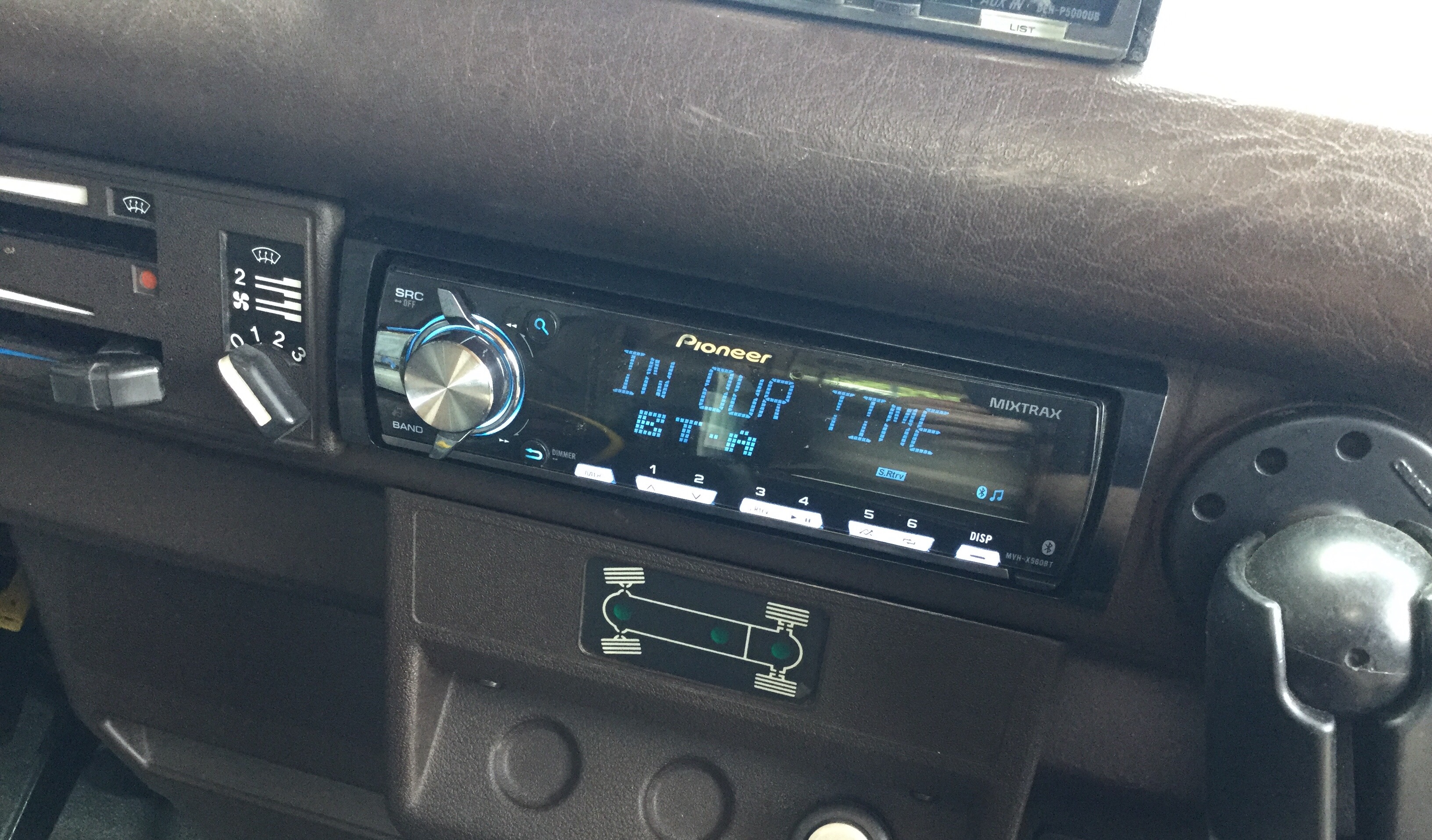
So back to the new unit, it has no CD player so it’s about half the depth of the old one and despite the inevitable rat’s nest of wires coming out of the back (again including three pairs of RCA jacked cables and an USB cable) it fits delightfully easily into the van.
It has built in Bluetooth which pairs up quite quickly and consistently with my devices, external mike for hands free phone, a remote control, wired USB input.
The controls are not bad but not great. I find them better than the old unit, especially for menu access and also for adjusting things when driving. Don’t get as many bump induced accidental choices.
Looking straight down thru ashtray hole.
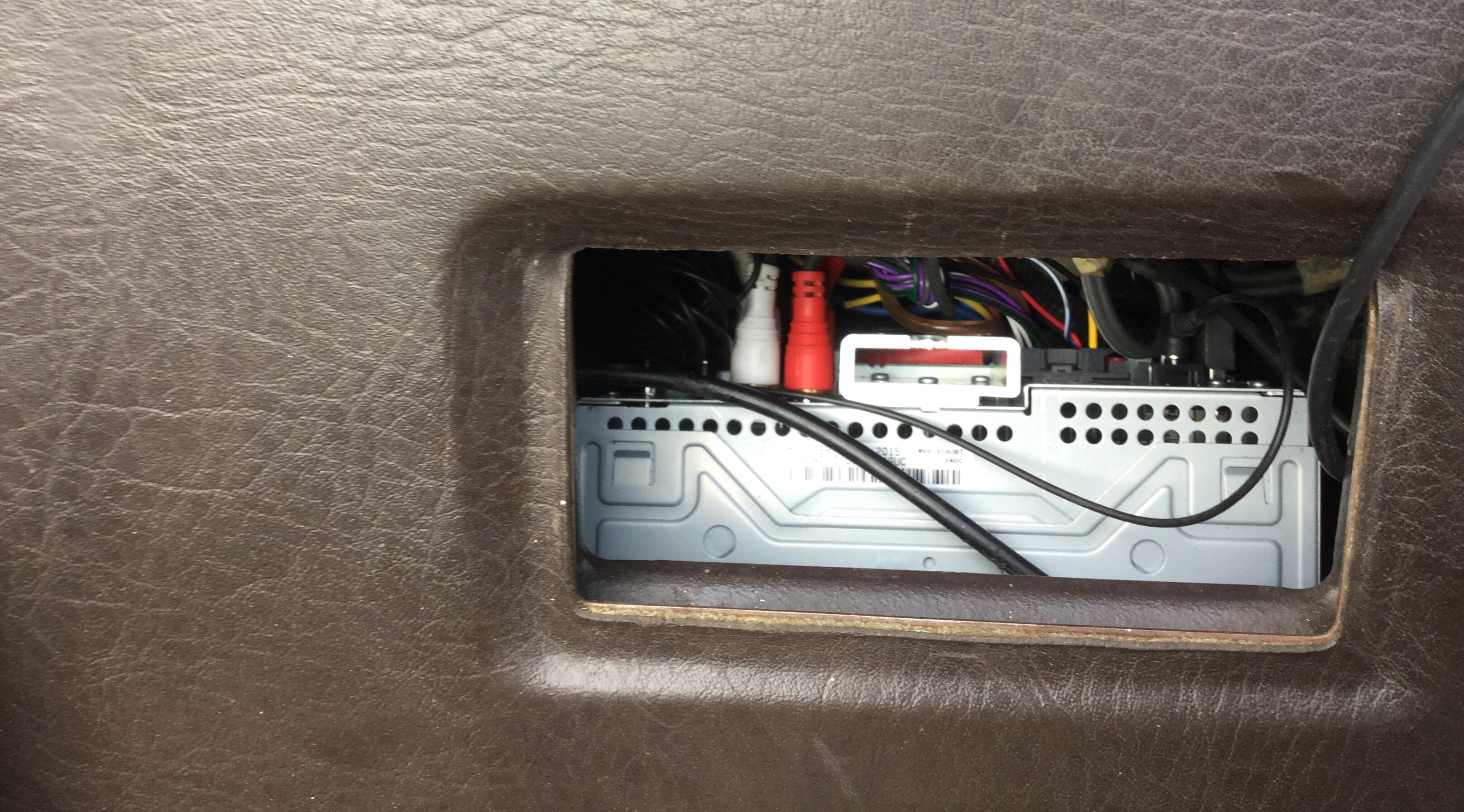
Maybe this shot shows reduced depth better. Pic taken at an angle.

The old unit sitting on dash. Looks really huge now.
I stuck the mic here, not the best spot perhaps.

And same ashtray lurking dongle in case of wired USB need.

Btw, the head unit feeds an old Blaupunkt 2 channel amp mounted infront of the glovebox. One channel feeds a pair of BA crossovers that feeds tweeters behind stock grill in door, and 6.5″ units at bottom of the door. The other channel feeds a pair of 4″ speakers back on the overhead cupboard.
Vanagon – fresh water pump update
Posted by albell in vanagon, vanagon mods on July 17, 2016
A few posts back I described how I installed an inexpensive diaphragm put in the van. I did it quickly, was keen to try it out on a trip. The other day I relocated it to what I think is a better spot.
I removed the in tank pump, the bilge pump type unit I was using as a stock replacement, and pulled the electrical wires out through the hr grommet at top of tank. I sealed the grommet wi a 1/4-20 stainless bolt and nut.
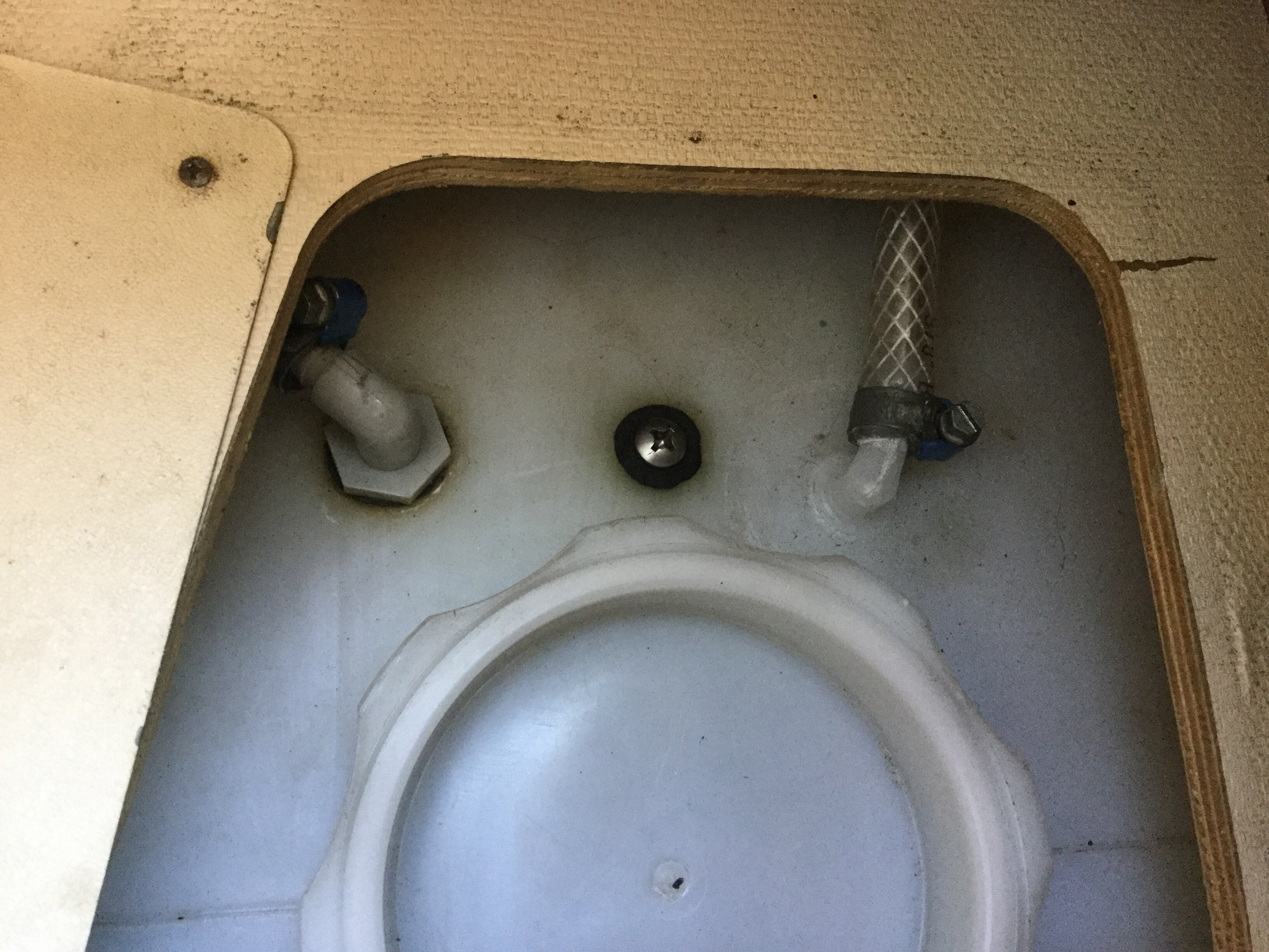
I shifted the little black box that is the water level indicator unit ( for the old style water level system) so that I could screw the pump to the wall between the cupboard and tank.
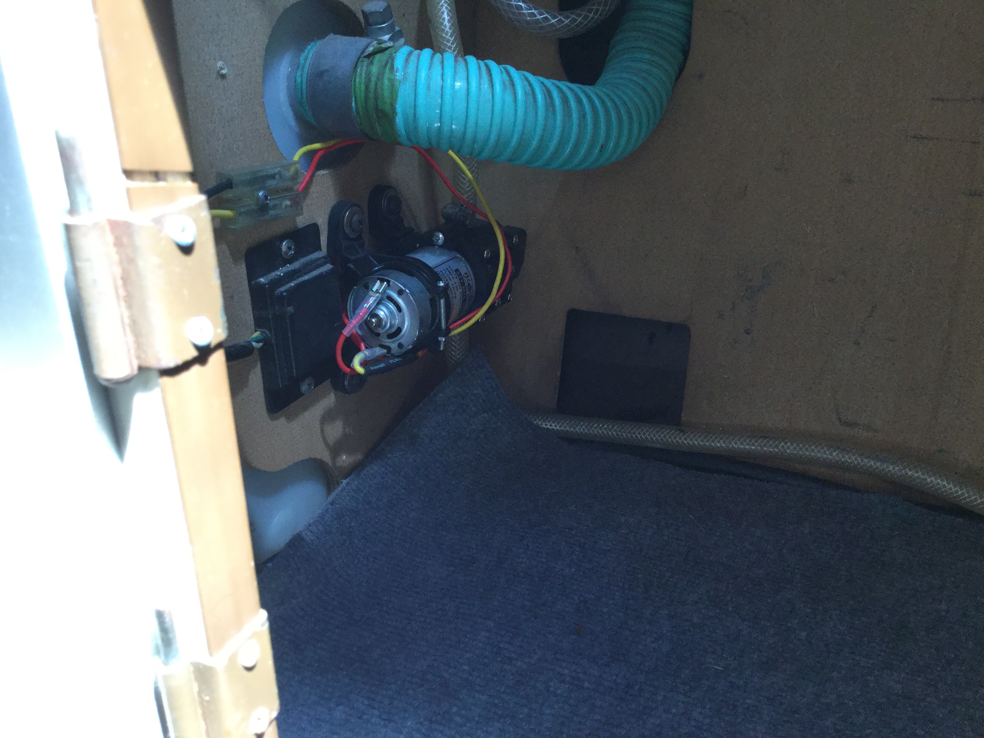
Electrical connection was very convenient, two wire plastic connector right there, just swapped over from the old pump.

You notice that the little wall that separates the cupboard from the wiring has been removed. I, like many other owners, removed that wall early on to gain a little bit more cupboard room. To protect the wiring from shifting cupboard contents, I screwed on a bit of the cheap carpet I’m using as cupboard bottom liner.
The pumps is a bit quieter back here. Still louder than the in tank pump, but considering the increase in flow and pressure, the additional noise is really acceptable. And for goodness sakes, just how long are you going to have the faucet turned on? 🙂
There is one, or maybe two, more things I’d like to add the the install. First one I will certainly will do, and that is add a relay back up front under the sink. You see, the eurovan faucet wiring is pretty skinny stuff. It’s not a long run from where it connects to existing wiring, but I’d rather that the switch is not handling the full 2.5 A of pump draw.
The second improvement that I probably won’t get around to but would be neat, is a little pressure tank accumulator. It’s what’s used in other RV and marine installs. Not sure if I really need it and if I am willing to devote space to it, I’ll see.
Vanagon – those boring wheels on the van
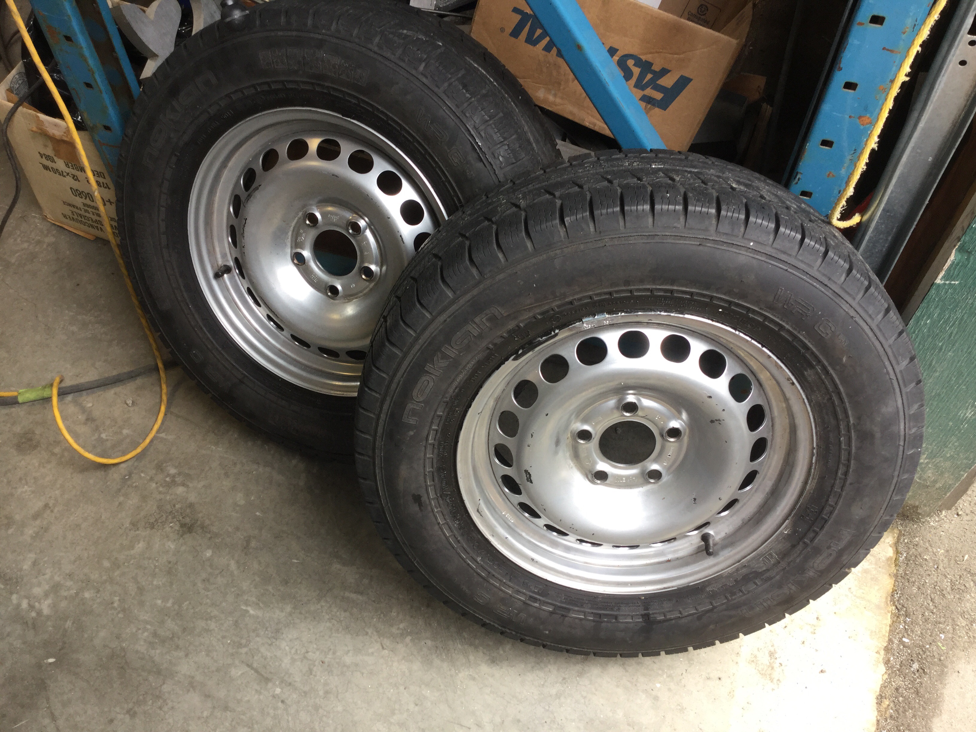
Yes, this is Simon’s latest find. 88 syncro high top. Getaway van conversion, done over on the mainland (BC). I’ll have more to say about this van and pics of the interior when Simon is finished tidying it up. It’s a good looking van, and only 82,000 km. The bored out wheels look ok on it, but we both agree it needs about an inch of suspension lift to perk it up.
Yes, it’s the same Fiberglas hightop that we put on Simon’s other syncro. If you had to have a hightop, and you don’t have access to the sexy European models, I think it’s the best looking option.
Vanagon – boring steel wheels
Posted by albell in vanagon, vanagon mods on July 9, 2016
Old Simon, yes the guy who has the hi top 91 Westy and recently the syncro double cab, bought another vanagon a month or so ago. I haven’t posted about it yet, I’ve been waiting for some of the little improvements to it to be finished.
One of the improvements is better wheels to replace the stock 14″ that the van came with. Simon found four 15″ steel wheels but the dolt went ahead and had tires mounted before the centre holes were opened up. I’m still cursing him for that. Without the tires I could have mounted the rims on the big lathe and the job would have been a snap.
The original bore hole size was something around 56 mm diameter. We needed to have them opened up to at least 66.4 mm. I fussed around with making a dedicated boring tool to use in the mill, but I ended up using a roughing endmill and the big rotary table.
I should mention that I haven’t done this job before, take my technique and approach with a hefty grain of salt.
As big (and darned heavy) as the rotary table is, the tire and wheel is bigger. Wheel on the table with inside face up, and the outside face sitting on blocks on the table so that the tire is taken out of the clamping set up. Not a great shot here, but you get the idea.
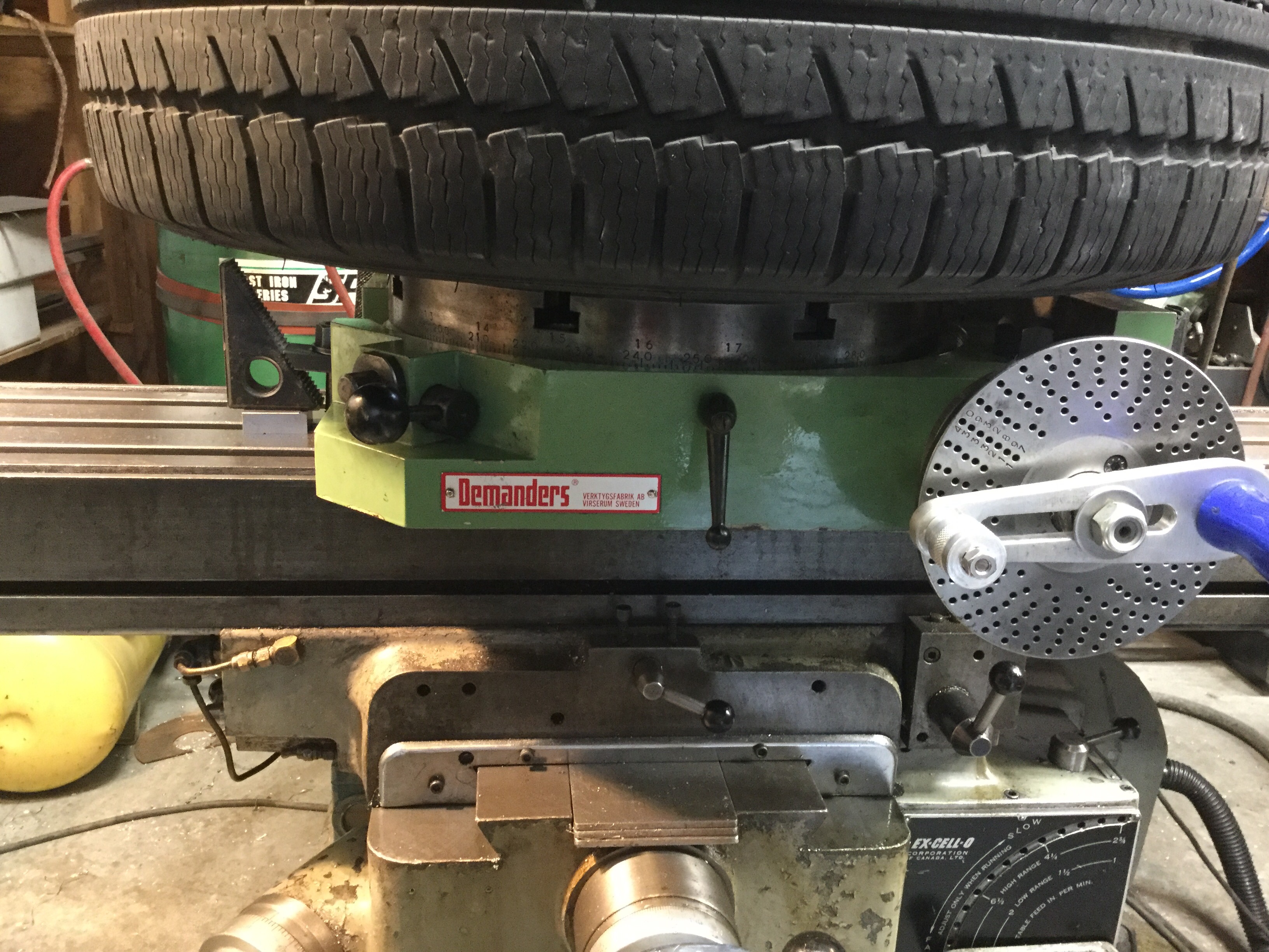
Oops, I skipped a step, the rotary table has to be centred directly under the spindle of the mill. This particular table has a #4 Morse taper hole and I stuck a little lathe live centre in there and indicated off that. Ok, I have to state right now that this entire boring process does not need to have super precise set up. The wheel is lug centric, the centre hole is just a clearance hole. Still, it was worth it to go through the motions to be semi precise. I centred the table to within about 1-2 thou. Good enough.
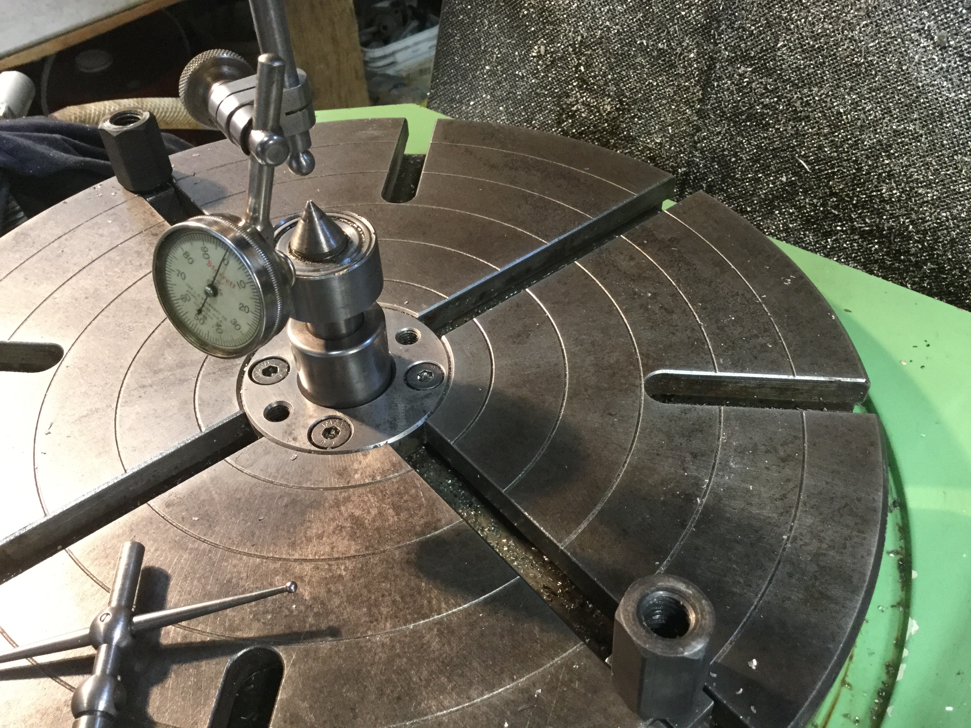
Then the wheel is humped up onto the table, on blocks, and loosely clamped. I discovered that the collet holder bevelled end fit into the unbored wheel well enough to get a rough centre alignment.

Clamped the wheel down onto the table just lightly and then I indicated the hole, got it pretty well centered ( again, around 1-2 thou) and, as the British would say, nipped the cramps down firmly.

Ok, endmill inserted, it’s a 7/8″ HSS roughing endmill. Moved the mill table over until the cutter touched the side of the hole, set my dial on zero. Yeah, no DRO on this mill yet. I had calculated a total depth of cut of 0.217″/5.51mm on the radius. That would give a diameter increase of 11mm, making the enlarged hole nominally 67mm.

So once touched off, I cranked in a depth of cut ( that varied between 0.070″ and 0.020″, I did a finishing climb cut at the smaller value). I cranked the rotary table and the wheel rotated and the cutter cut. I have a shaky video of that.
Exciting stuff eh?
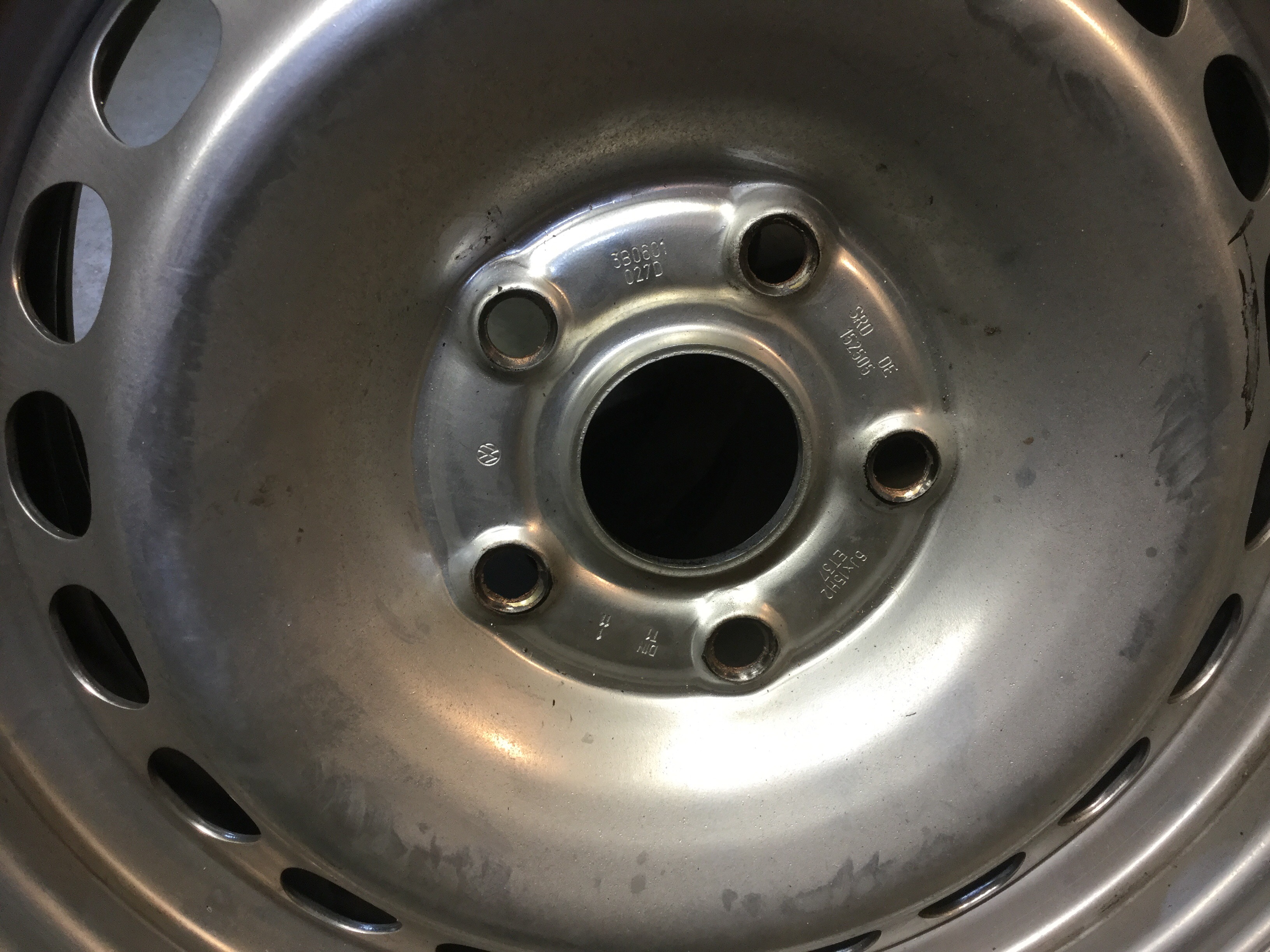
In the end, the wheels turned out pretty good. The surface finish with the roughing endmill was acceptable. How about before and after shots?
Unbored
Bored (aren’t we all?)

This was one of those jobs where the set up took far longer than the actual machining.
Vanagon – Westy fresh water pump experiment
Posted by albell in vanagon, vanagon mods on July 1, 2016
Bought a cheap water pump from banggood, this one. The original Westy in tank water pump had bit the dust a few years ago and I have been getting by using a small bilge pump similar to this.
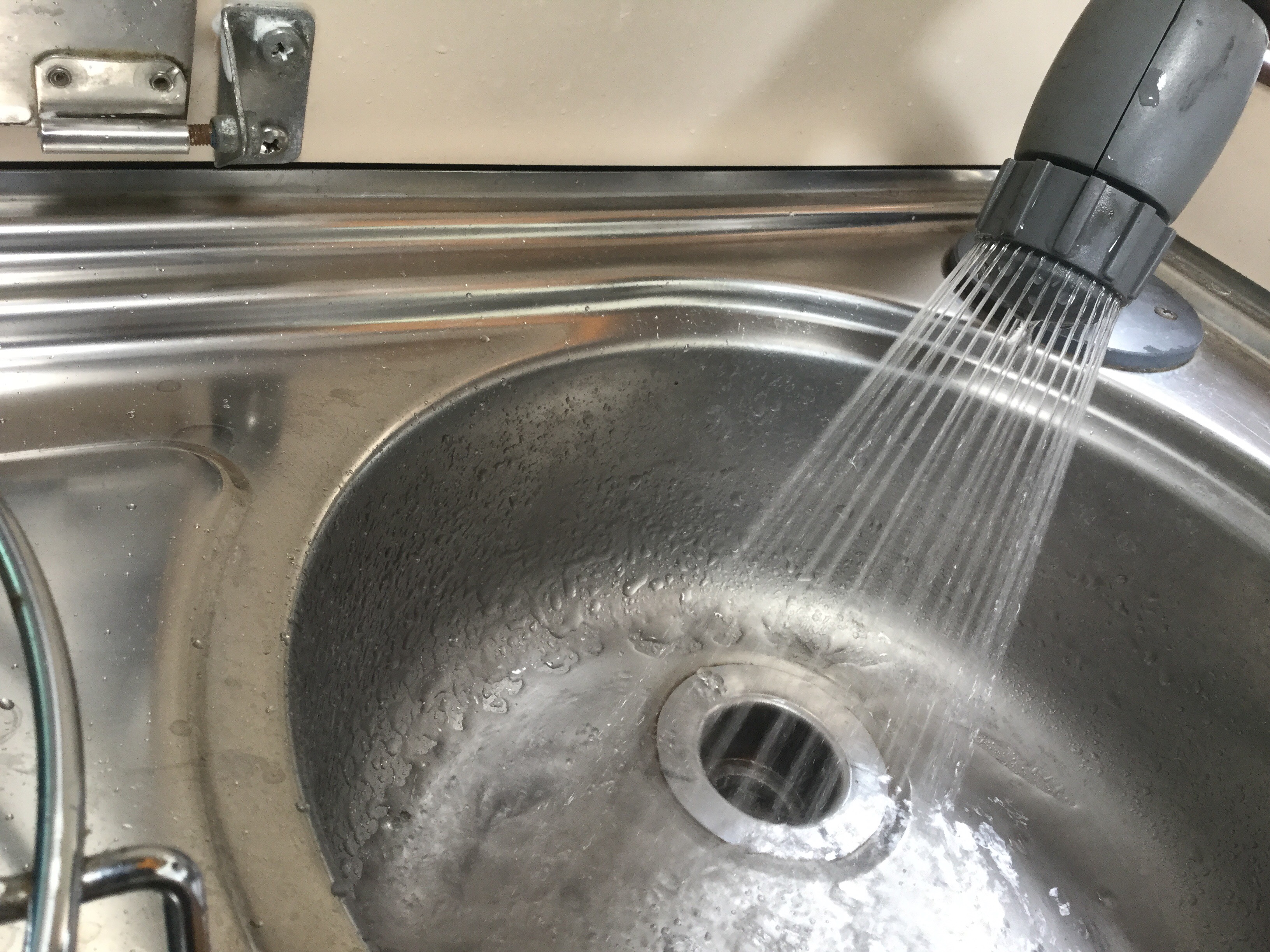
It works ok I guess, had to adap the outlet to match the Westy plumbing. But it didn’t push as much water as I had hoped. For years I have been using a Eurovan Westy extendable faucet and I had dreams of being able to pull the faucet out through the sliding window and get a refreshing blast of cooling water on a hot summer day. Especially because the faucet has a spray setting. With the bilge pump, and the stock Westy pump before, the promised spray wasn’t that impressive.
I know that many sailboats and RVs use a pressurized water system with a pressure activated pump and an accumulator. Tempting to try this I thought.
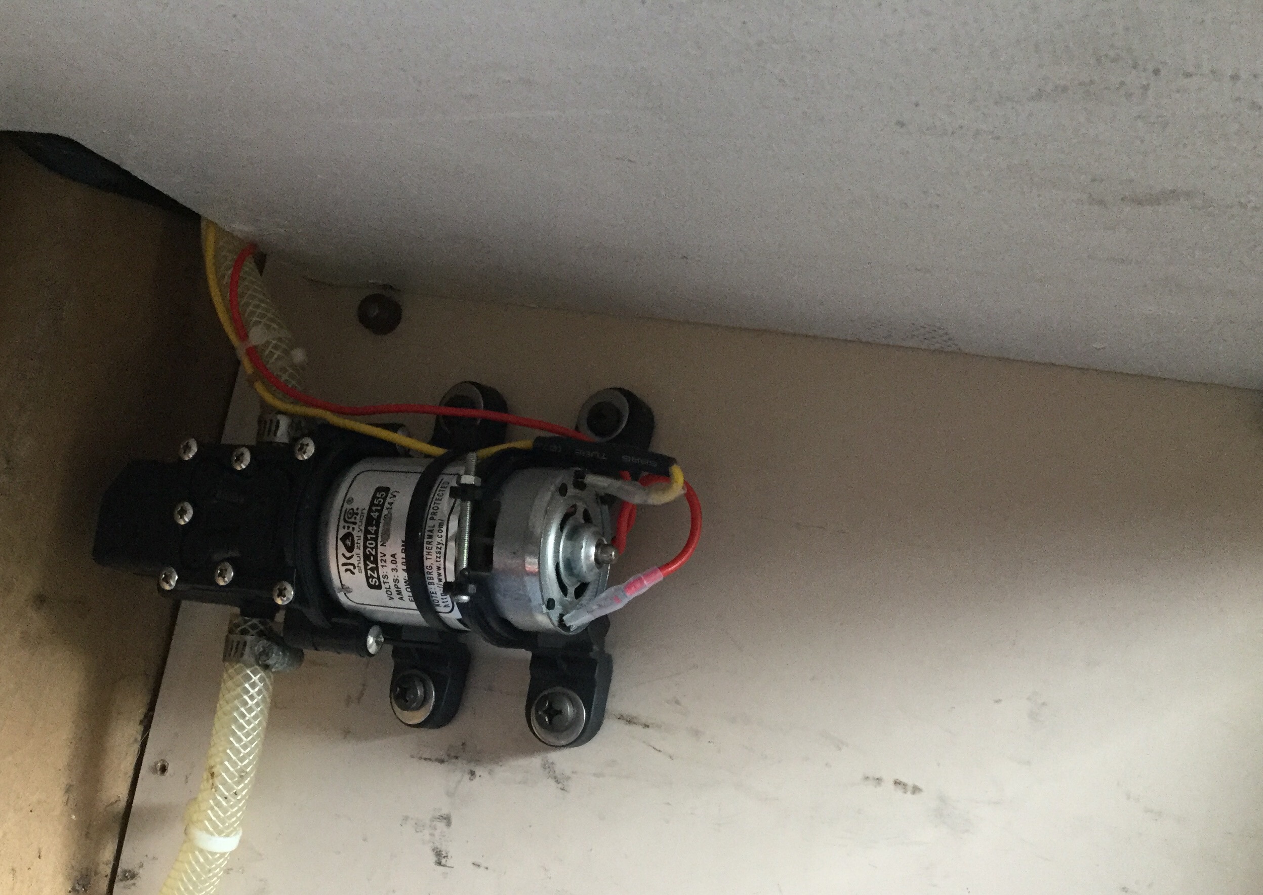
So I buy the banggood pump, and arrived the other week. Supposed to produce 100 psi ( well that’s the switch cut off setting) and 4 L/m volume. I rushed out and did a quick install just to see if it will make my shower dreams come true. I simply plumbed it inline and connected its power lead to the switched side of the Eurovan faucet wiring. So the pump comes on when the faucet switch closes. Not a pressurized system and no accumulator.
Note that I did mount the pump at a slight angle to ease stress on the tubing. It had nothing to do with the awkward position I had to assume to get in there and screw. Nothing at all. I might find a better spot for the pump.
Does it improve things? Hell yeah.
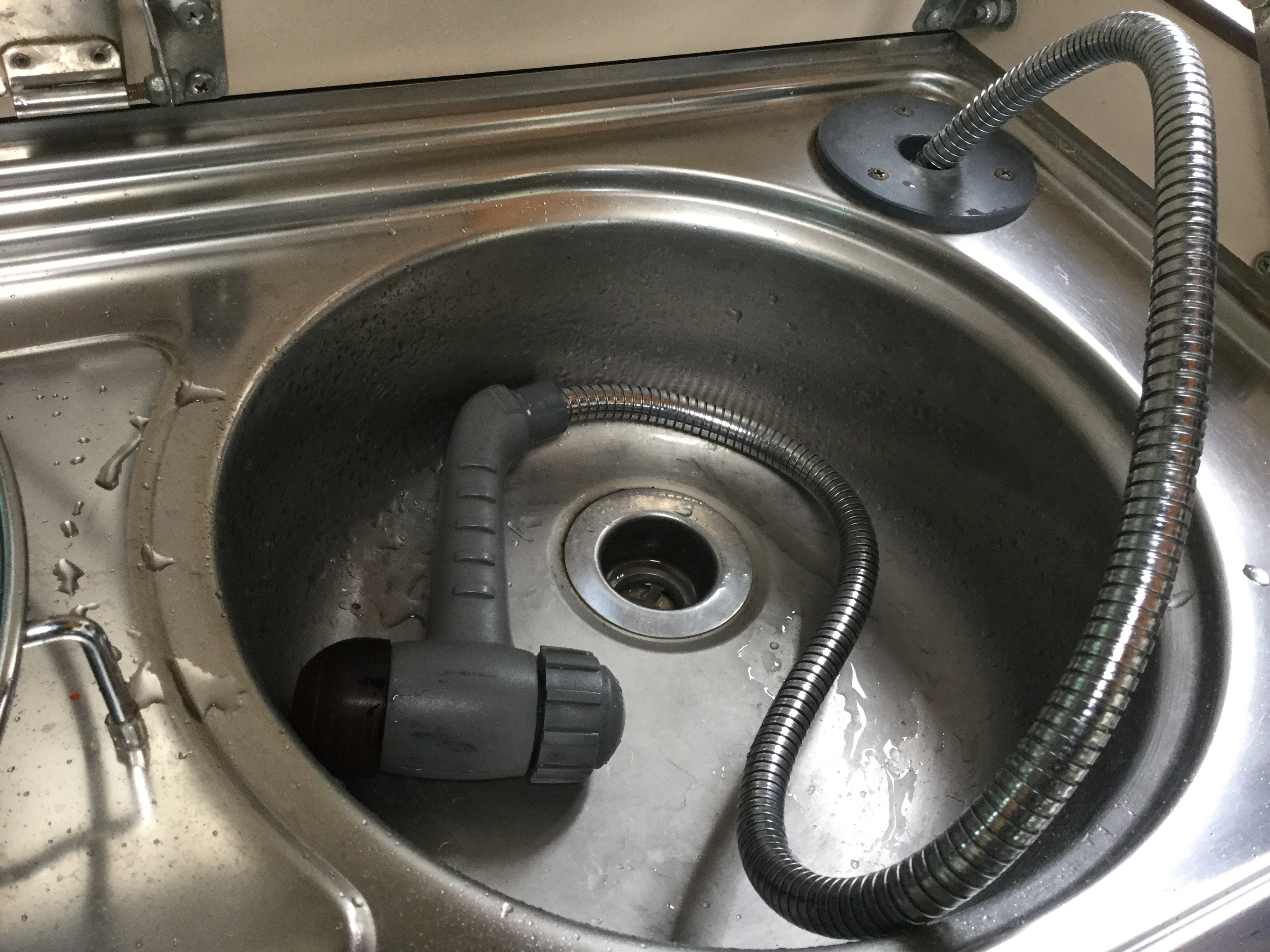
Shot of the extension of the faucet. Has to be stored like this to allow the lid to close. It’s too tall when in its mounting hole.
It is noisier than the in tank pump alone. Yes, to be clear, the in tank pump is still connected and runs in tandem. I’ll pull it out of the tank later.
Vanagon – Propex heater install part III
Posted by albell in vanagon, vanagon mods on July 1, 2016
Finally, it’s done. The last bits aren’t as neat as I had hoped, but hey, it works. The console port for the heated air outlet really doesn’t look great. Problem was the console itself is made from such cheap material that it couldn’t stand up to my hacking.

Now the thermostat, where to mount it? Constraints be two. First is I couldn’t be arsed to find some replacement 5 wire cable so I reused the original but with the fire damaged section cut out and the the cable spliced. So the shorter cable limits the range of thermostat placement. Secondly, the cable enters the thermostat from the rear, to make a clean surface mount. That means a hole drilled somewhere and the cable routed through God knows what. Instead of a surface mount I made up a very crude swing away mounting plate from some stainless and added crash bars. Mounted this on the forward face of the kitchen unit, right behind the driver’s seat.
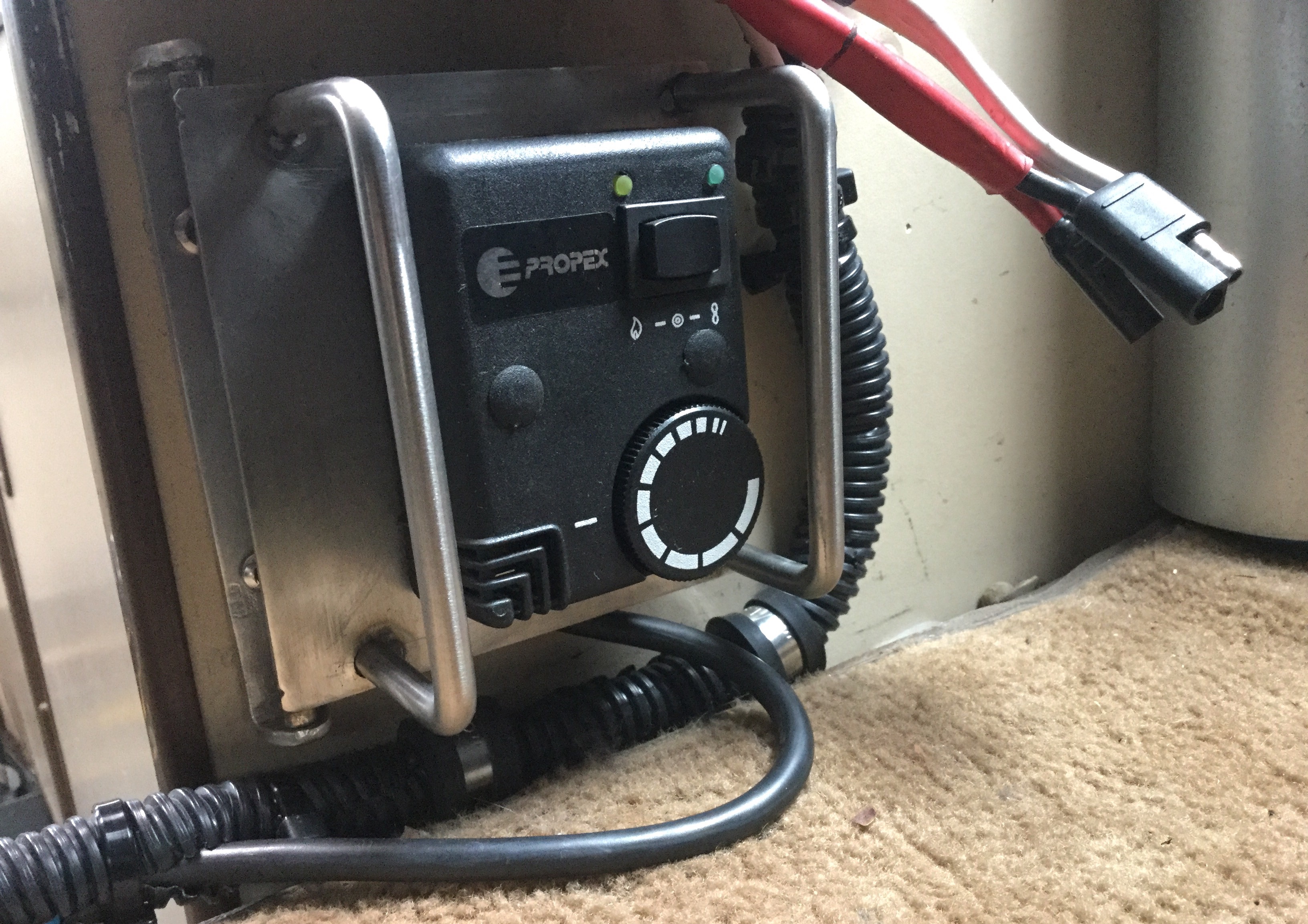
It’s held back by a magnet. Swung out its pretty accessible .
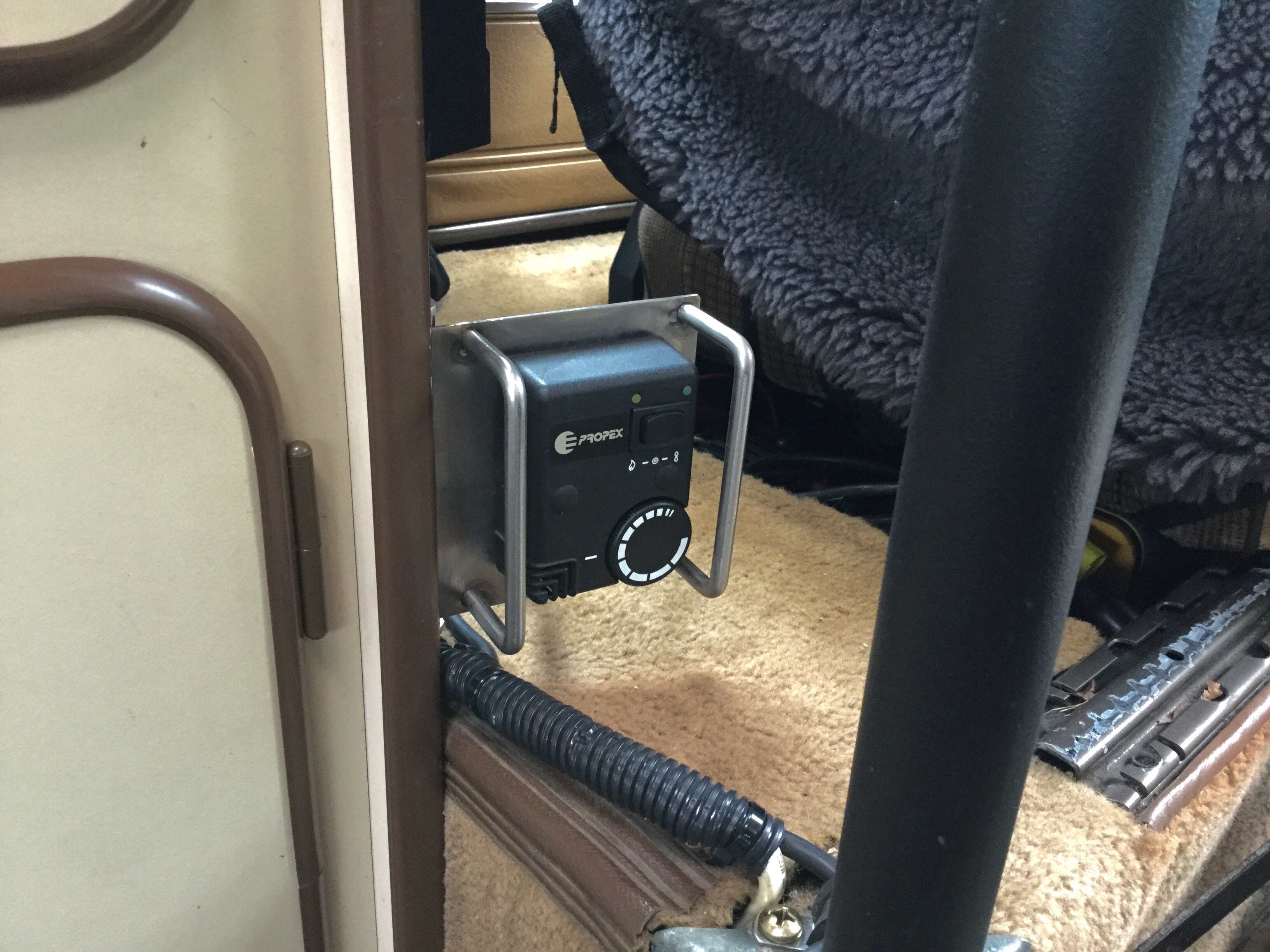
So is this a good spot to monitor cabin temperature?
I’m pants at running wires neatly. Start out with the best intentions but it ends up looking slapdash.
The heater really throws out the hot air. Without a diffuser on the outlet it’s an air stream like a hairdryer. And it’s not whisper quiet. But it will heat the van and that’s the important thing
Vanagon – Propex heater part two
Posted by albell in vanagon, vanagon mods on June 27, 2016
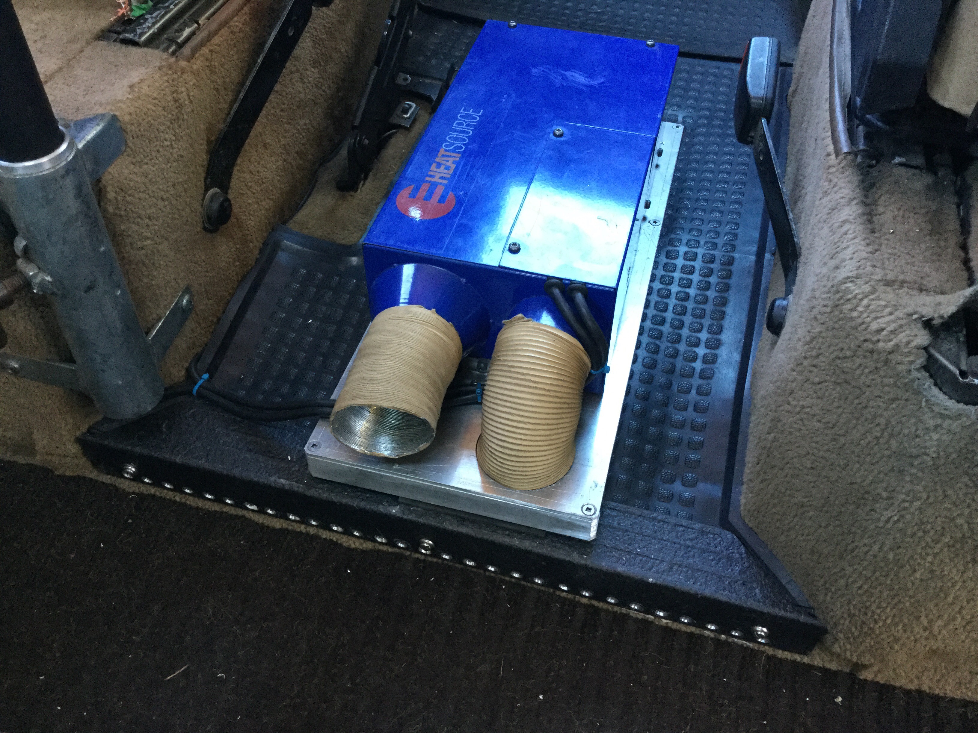
I mentioned before that Simon had installed his heater inside his between seats console. I was planning to do the same but I got sidetracked by another idea. I needed a box to enclose the heater, a barrier between the heater and the console. Once again the scraps of aluminum honeycomb material I got from Donovan at Western Edison popped up. I wanted a box that wild be stiff enough to take someone standing on it and the honeycomb was the obvious choice for stiff and light.
Here it is, just butt joints all round with a fillet of PL Premium polyurethane adhesive holding it all together. Some of the exposed honeycomb I filled with bondo. I scuff sanded it all over.

And then I must have had a mini stroke as I decided to try sticking on some old veneer I have had hanging around for years.

This is the first time I’ve tried veneering anything. Back in the day when I did woodworking as a hobby I was fully into oldtool, split, hew, and plane type of work. Thought that veneer was somehow dishonest. Oh the arrogance of youth.
The bit of veneer I had was not large enough to be able to match grain direction so it turned out to be a bit of a dog’s breakfast. And the corners and edges were not perfect. I hit the corners with sandpaper enough to let a thin line of aluminum show.

Mid century moderne? Late sixties early seventies British speaker style? Drunken Dieter Rams? You might have a better description 🙂
I attached a rare earth magnet to the inside of the box and that really helps to hold the box in place as it grips the heater. Heating air intake is drawn from through the mounting plate and in from the gaps at the rear most part of the plate. The floor slopes away so it turns out that the gap is pretty well equal to the air intake opening.
I could just use the heater as is, but then I would loose the console storage. So I decided to cover up my lovely creation (!) with the console. I took it apart and cut sections out of the cubbies, welded ( hot air and a screwdriver , yeah nasty) the cubby bases back in. Now the console fits down over the box, albeit with less cubby storage room.
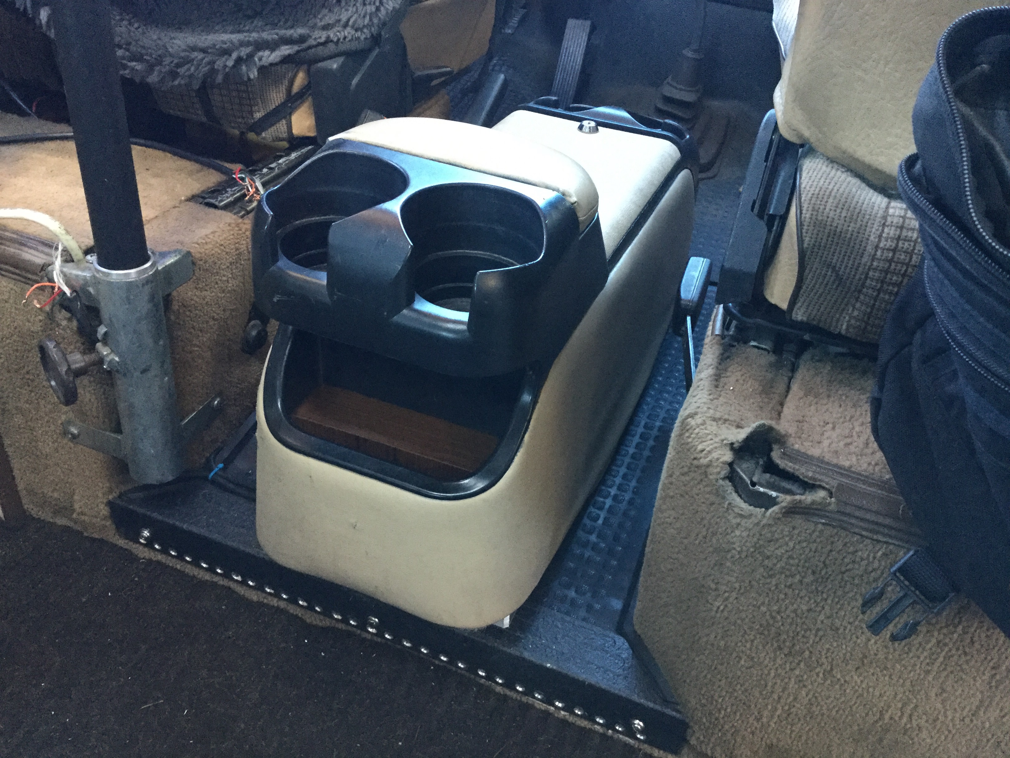

No, the hot air ain’t going to come up out of that opening. I’ll cut out the rear end of the console.
Oh, almost forgot about how the heater combustion air intake and exhaust lines are routed. It’s a bit of a pain to connect them up over the front diff, but the intake comes back down and is secured to frame rail near propane tank.
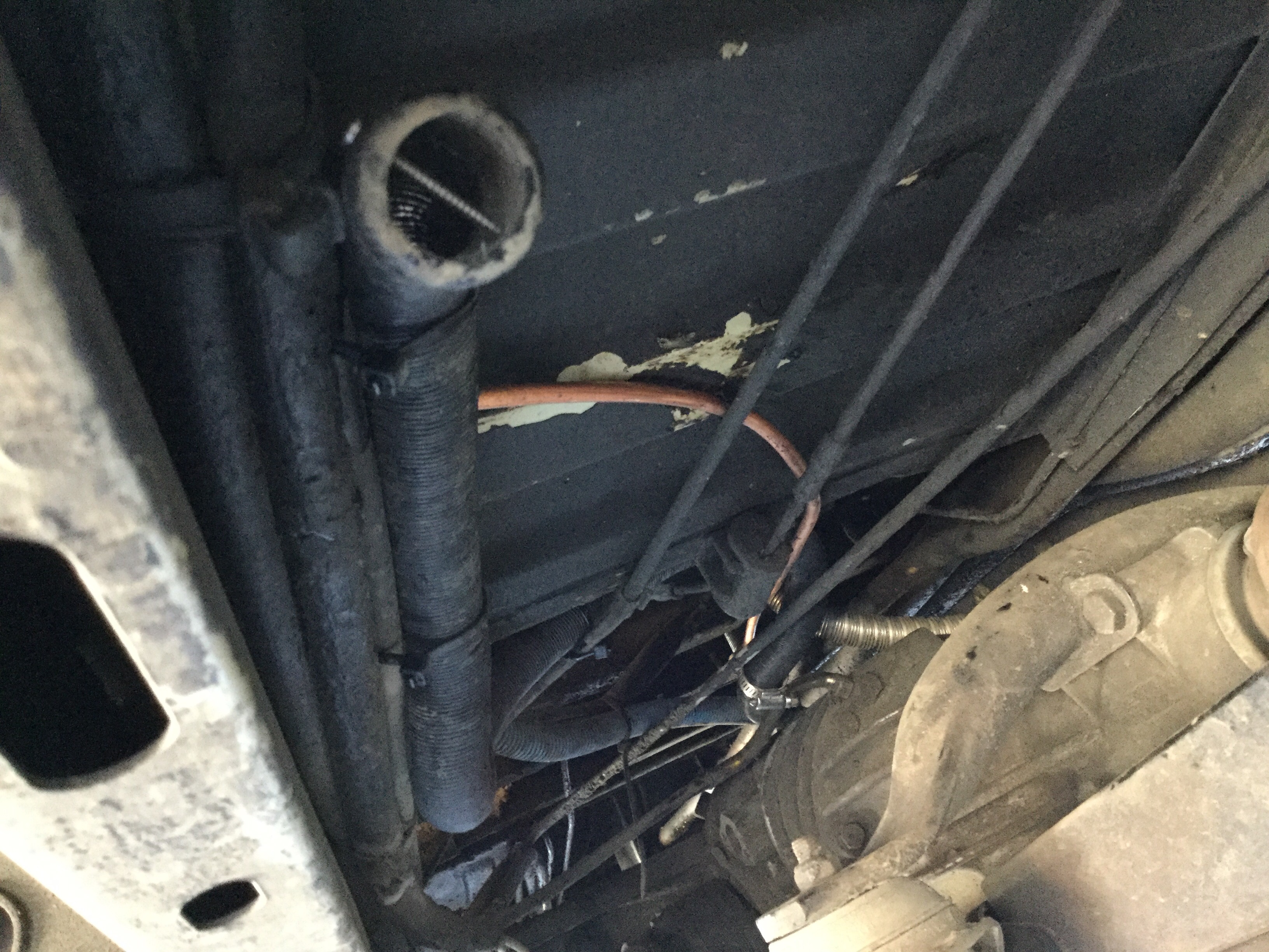
Hey you see the un-secured gear clamp on the black intake line? When I took the pic I hadn’t got that bugger forward and up into place.

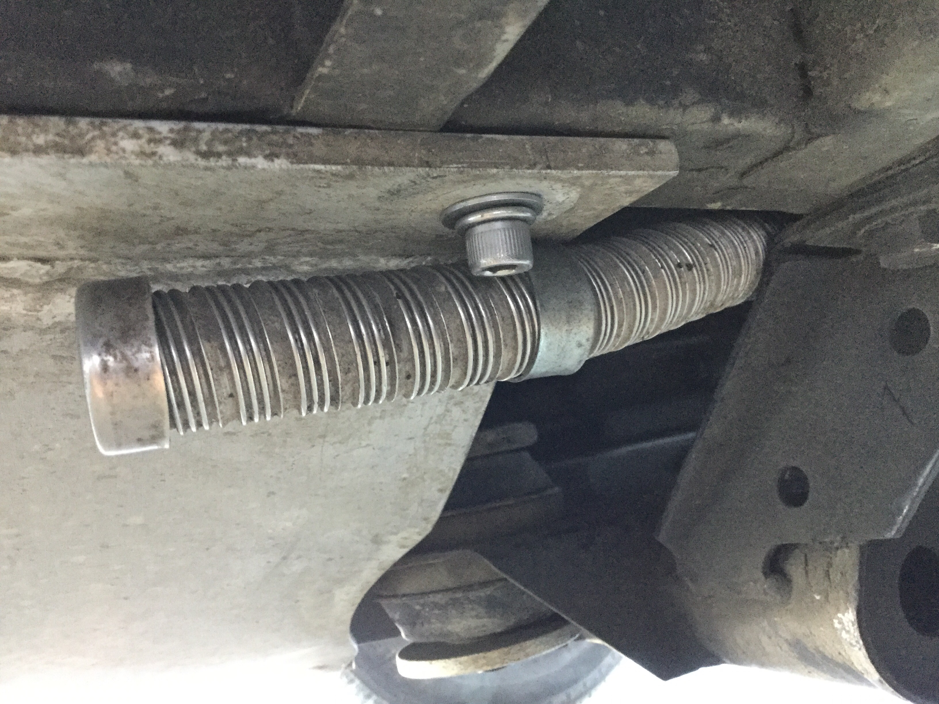
And the exhaust line comes back down on the passenger side to end up at the forward edge of my lateral skid plate.
I’m finishing up the thermostat mounting and wiring, and doing the console rear end mod. That’s for the next post.
