Archive for April, 2010


Battery info
Nice little document with lots of good stuff on lead acid batteries and simple chargers (with schematics).
batterydoc
Weekend trip in April
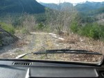
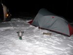
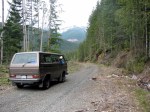
Went on a quick overnight trip with my son. Ended up on a logging spur road between Cayacuse and Port Renfrew.
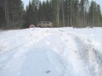
Then on to Port Renfrew and back around to home. Snaps below, note: roads were steeper, and snow deeper than they appear in the pics 🙂
The big Sitka Spruce (Harris Creeks spruce, and Harris creek also shown in the rocky sided gorge pics, taken at different points on the creek) is bigger than it appears. Base of tree as wide as the Vanagon is long.
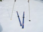
Hey you trendy modern free heel skiers, don’t laugh at my mismatched poles and 80’s vintage TUAs with those wimpy bindings.
Oh and one more thing, skeleton pic… we found this just off a logging road. Looks like 2 skeletons in that pic, a third was a few feet away. No legs or skulls.
Update: looking at skeletons again, I’m guessing Black Bear. Lack of feet and skull good clues too.


Request for viscous coupling

If anyone has an old clapped out viscous coupling they would like to donate, please leave me a message in the comments. I’d like to take one apart, look at the seals, the plates etc.
Auxiliary fuse panel
Posted by albell in vanagon mods on April 6, 2010
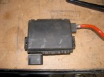
I found this handy little fellow on 2002 model year New Beetle ( I believe they are in Golfs/Jettas too). I used it on my 82 I4 engine westy, attached right on top of starting battery as an auxiliary fuse panel. I had it wired to an automatic charging relay (Blue Sea systems #7600) and “house battery”.
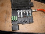
Its handy to have those 4 fusible links (2 X 110 A, 2 X 50 A) and 3 spade fuses to connect various accessories.
Addendum: I now have it installed in my ’86 syncro, mounted under driver’s seat. Instead of using the stock pigtail I’v introduced power from the Blue Seas ACR (which is mounted under passenger seat) into the box via the connection to the fusible link on the right. My auxiliary battery positive is connected to the next fusible link. I have tapped power via the 3 spade connection (with the spade type fuses) on the left:
-one to the kitchen unit for the water pump, fridge (not 12 V cooling function though), and indicator lights.
– one to my stereo head unit
– one to connection E3 on back of fuse panel (see this post)
Syncro running gear layouts
Nice to see it all laid out like this. First we have an overview of viscous coupling installed driveline. This has both rear and front differential locks.

Another view of same.

And here we have the much much rarer version. No viscous coupling, where it was is now a straight shaft. Power to front is now controlled by a de-coupler housed in nose cone of transmission.

And here is cross section of the front differential, showing viscous coupling install.

And a cross section of the rear differential and transmission.
![]()
Syncro front diff. removal
Posted by albell in syncro, syncro specific repairs on April 3, 2010
Look, its cold and windy today, hail at times. I don’t want to freeze in my cold workshop so I am sitting at the computer, ok?
Courtesy of Kafer and Co., Homburg/Einöd is this pdf file showing how to remove your syncro front differential when you want to swap in that new or rebuilt viscous coupling. PDF with pictures, about 800 kb.
A wide open viscous coupling
Graphic shots here from the Wikipedia entry on viscous coupling. I think they were supplied by some English chap who cut open a failed unit. Note the colour of the fluid, I wonder if this colour is due to old age break down, metal particles, or its the stock colour for the polymethylsiloxane and any additive the maker adds. The plates have either notches on the outside (engage with VC housing and flange shaft), or on the inside (engages with pinion shaft). The piercings on the plates are there to reduce heat induced warping. I think its the tiny burrs produced when those plates are pierced that are referred to in the abstract posted previously.


Might as well throw in a sectioned diagram of the VC to perhaps make things more clear.

More on humping
Link bait title, teasing just like this abstract I found. Full text not available but it explains more about how the burrs formed during the piercing of the plates act in the humping state. Also interesting note at end about temperature mediated viscosity changes, something I have been railing against as the cause of torque transfer in the VW vc. I’m sticking with that opinion until proved wrong 🙂
Title:
Numerical analysis of torque augmentation in viscous couplings
Authors:
Pan, Chen
Affiliation:
AA(SYRACUSE UNIVERSITY)
Publication:
Thesis (PhD). SYRACUSE UNIVERSITY, Source DAI-B 59/07, p. 3659, Jan 1999, 153 pages.
Publication Date:
00/1998
Category:
Engineering: Mechanical, Applied Mechanics, Physics: Fluid and Plasma
Origin:
UMI
Abstract Copyright:
(c) 1998: UMI Company
Comment:
Publication Number: 9842398; Advisor: Lewalle, Jacques
Bibliographic Code:
1998PhDT…….126P
Abstract
The humping phenomenon in viscous couplings is investigated by the finite element method. The possible destabilizing factors suggested by the experimental results are divided in two groups: fluid properties and plate geometry. A simple two-dimensional model capable of including these factors was devised. Both Newtonian flow and Non-Newtonian flow in the viscous coupling were solved by our Finite Element Method code. The finite element formulation based on the variational principle is discretized by the mixed interpolation functions. Within each triangular element, velocities were approximated with a quadratic function and the pressure was represented with a linear function. The non-linear system of equations resulting from the discretization process were solved by Gaussian elimination and iteration procedures. As a result, several routes to humping in viscous couplings are documented. The plate permeability associated with the perforations was found to have no significant effect on the humping scenario. The initial loss of symmetry can be provided by random fluctuations of the axial location of the inner plates, or by the presence of burrs. Once the symmetry is broken, the left side burrs at the leading edge of the inner plates can initiate humping with a preferred direction of motion toward the burrs side of the inner plate. It was found that viscous coupling have an ability to recover from the plate torsion. The fluid properties of the silicone oil are also associated with the humping. After examining the power law model, the visco-pseudoplastic model and the temperature-dependent viscosity model for the variable viscosity, it was found that only visco-pseudoplastic model and the temperature-dependent viscosity model can be used to explain the humping. For some transition shear rate (233.3</bar Str<816.5) in the visco- pseudoplastic model, the axial forces will increase the given asymmetry and initiate the humping. For the temperature-dependent viscosity model, the axial force initially stabilized the inner plate, after passing the transition time (0.028 sec), the axial force will destabilize the inner plate and initiate the humping.
Viscous coupling hump condition
Posted by albell in syncro, vanagon tech papers on April 2, 2010

I’m still curious as to how the viscous coupling goes into the hump state. My earlier posts with accompanying documents mention the hump state wherein 100% of torque is transferred from input to output shafts. Recall how the silicon fluid (some form of siloxane) thickens under shear stress and so begins to transfer torque. This shearing increases temperature and consequently pressure inside the coupling housing. VW’s own publicity literature states that the temperature rise is what causes the increase in fluid viscosity, but this research paper disproves that.
The problem I had was wondering what pushes the plates closer together to create the hump state. Just saying pressure increase does not cut it, for the coupling is in a sealed housing and pressure increase should be the same on both sides of the plates.
One thought I had was that there were localised asymmetric pressure increases, but I still had a problem with that as I thought pressure increases would be equalised quickly in a fluid.
Well I was half wrong, the following excerpt from a research paper by Mohan (2002) shows localised pressure increases forcing the plates together. Its a little like tilting your hand out the car window, or is it? Examine diagram closely and make up your own mind 🙂
Oh, STA, self induced torque amplification, is another term for the hump state.

So, as I see it, the progression goes like this:
-rotational difference between input and output shafts (ie front vs rear wheel speed difference, above the 5% or so allowed slippage) causes shear and increasing viscosity in the siloxane fluid.
– at some point, localised pressure differences between plates force the plates together, in effect coupling the input and output plates. Remember the plates are very close together, and one set is on a splined shaft and is free to move axially).
– then the standard story applies, when the plates are coupled there is no relative speed difference between the plates, the shear is gone, and the viscosity drops again, the plates separate and if the input and output speeds remain sufficiently different then the process repeats.
But one thing still puzzles me, in this paper (yes, same one referred to above)
vc-paper
the author notes the pressure increase inside the coupling during slippage, and wonders if some sort of pressure control on coupling could affect the hump state behaviour. I still haven’t resolved how overall internal pressure affects localised inter-plate pressure differences.
And to cap it all off, GKN Drivelines (heir to the Ferguson developers of the viscous coupling) published this bit of info:
See how the diagrams resemble Mohan’s diagrams above, But then they go on to say:
“The “Hump” mode is activated when the coupling achieves 100% filling due to fluid thermal expansion thereby amplifying a hydraulic throttling effect between the plates”
This statement is sort of misleading. Makes you think that the thermal expansion is general (which it is) and not localised (which it is too).
Oh and that reminds me, as you know the coupling is not filled 100% with fluid, there is a small amount of air left in (what is it, 7-12%?). This air ends up distributed, apparently, as small bubbles and acts as a moderating agent in how aggressively the coupling goes into the hump state. For instance, the less air left in, the more aggressive the coupling will be.
Call me an obsessed nerd if you will, but I wish the developers of the viscous coupling (Ferguson et al ?) would call me up and invite me over to explain all 🙂
Rad. temp sensor story
Local friend and ’91 syncro Westfalia owner called me last weekend for some help in tracking down an unusual problem. I’ll list the symptoms in point form:
– he had been away for a couple of weeks and the van was parked.
– when he came back the battery was dead.
– his wife noted that the van was making “ticking noises”.
– when he used booster pack to start van, the radiator fan came on and was making a “twig caught in the blades” noise.
– the fan would come on with ignition on.
His first thought was bad radiator temp sensor, so he disconnected it (lower right part of radiator, as you face the van). Even disconnected the fan would come on when ignition on.
I came over at that point and we first dropped the spare tire to look up at what the rad. fan was hitting to make such a noise. Turned out that the 15″ wheels and beefy tired spare had pushed up a section of black plastic tubing (which I am guessing is the brake vacuum line) so that the fan blades would hit it. It wasn’t worn away enough to make a hole, but it was close.
We then started to pull fuses to see why the fan would come on even with thermo switch pulled. Oh, I have to say at this point the van does not have, nor ever did have, air conditioning (a/c complicates rad fan control a bit). We were using the Bentley manual, following the wiring diagram for a 91 westy. Diagram below, you can see how pulling fuse#1 should stop any fan power.

We were puzzled for a bit, thing did not make sense. Also we noted the rad fan had 2 red wires leading to it where above diagram shows red and red/black.
Clearly we were on the wrong track. We looked through Bentley and found a wiring diagram for a 450 W rad fan (in 1986 model tear section).
Ah ha! This looked better.

We found the relay and 50 A fusible link above and to the left of the fuse panel, right above the grounding “crowns”. Remember, still at this time, the rad fan would come on if ignition turned on, even if fuse #1 is pulled and thermoswitch disconnected. Oh and also the wiring diagram shows a blue wire into the thermoswitch where the van had a red/blue wire.
We pulled the relay and lo and behold the fan would not come on, yah! Funny thing was, the relay checked out ok using multimeter and it clicked on and off when energised. Putting the relay back in made tha fan come on, but this time disconnecting the thermoswitch turned the fan off.
Geez, this is long winded and boring tale…
So we bought a new thermoswitch and swapped it in (this is not the time to tell what we found in the rad when we pulled old switch out) and everything worked as it should.
Note the erosion of the switch.
")
Theory time: we figure that when the van was sitting, the thermoswitch failed and allowed the second stage fan speed to come on. The brake booster vacuum line was worn and the battery drained. My friend’s wife must have heard it at the end of the battery life when the fan was slowly turning and making a clicking noise as it hit the brake booster vacuum line. This long run time caused the second stage relay to stick in the on position. Pulling the relay, the jiggling etc, caused the relay to open, and was then “under the control” of the thermoswitch, and again fuse #1.
Phew!
