Archive for category metalworking
Vanagon – Experiment in aluminum
Posted by albell in metalworking, vanagon, vanagon mods on July 21, 2023
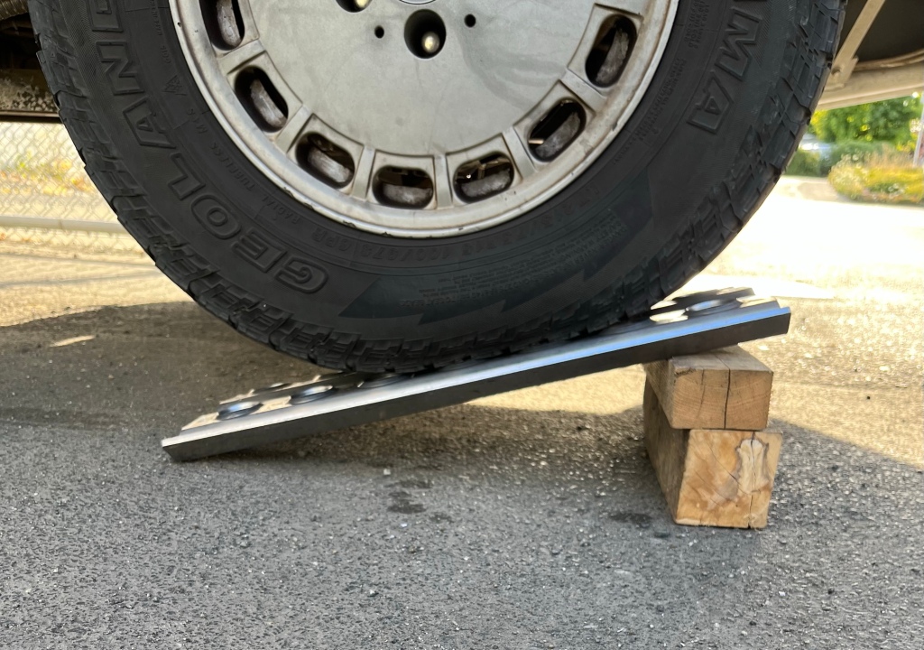
This Friday late afternoon silly project. I want another bridging ladder. I’ve given up on the section of fiberglass waffle board stuff I had been using. It’s heavy, it has large sized grit embedded on top surface ( really annoying to handle) and it really wasn’t thick enough … I think it was only around 34mm thick… would want 40 mm or so.
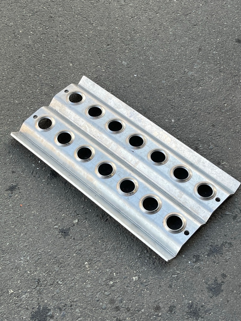
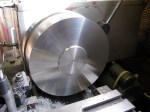
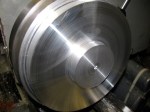
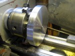
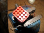
I thought I’d do an experiment with 1/4” aluminum. Make something about 30“ long and 10” wide.
But I was foiled , weren’t any off cuts large enough ( not going to cut into full sheet for this trial ) . So I scaled down to 22” long.
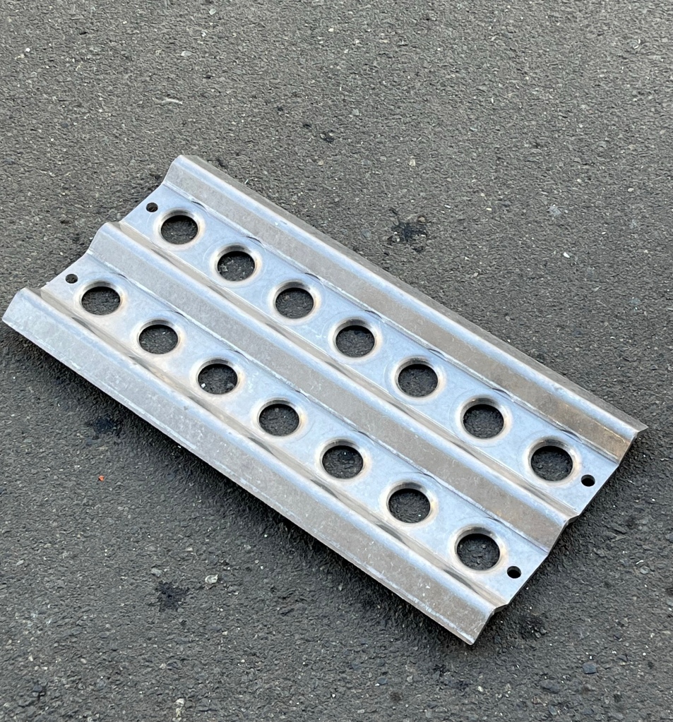
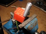
Ends up being a wee cute little thing. Good enough for a levelling ramp when camping. For scale, holes are 1.5” diameter , and dimpled.
No surprise it’s stiff , short span. I’d like to try again, same width and the Orginal idea of 30” long.
Vanagon – one more hatch ladder/tire carrier
Posted by albell in metalworking, vanagon, vanagon mods on April 27, 2016
I’m rushing to finish this one so I took some pics while I still had the presence of mind to do so. Shooting into the sun and using the iPad, not the best formula.
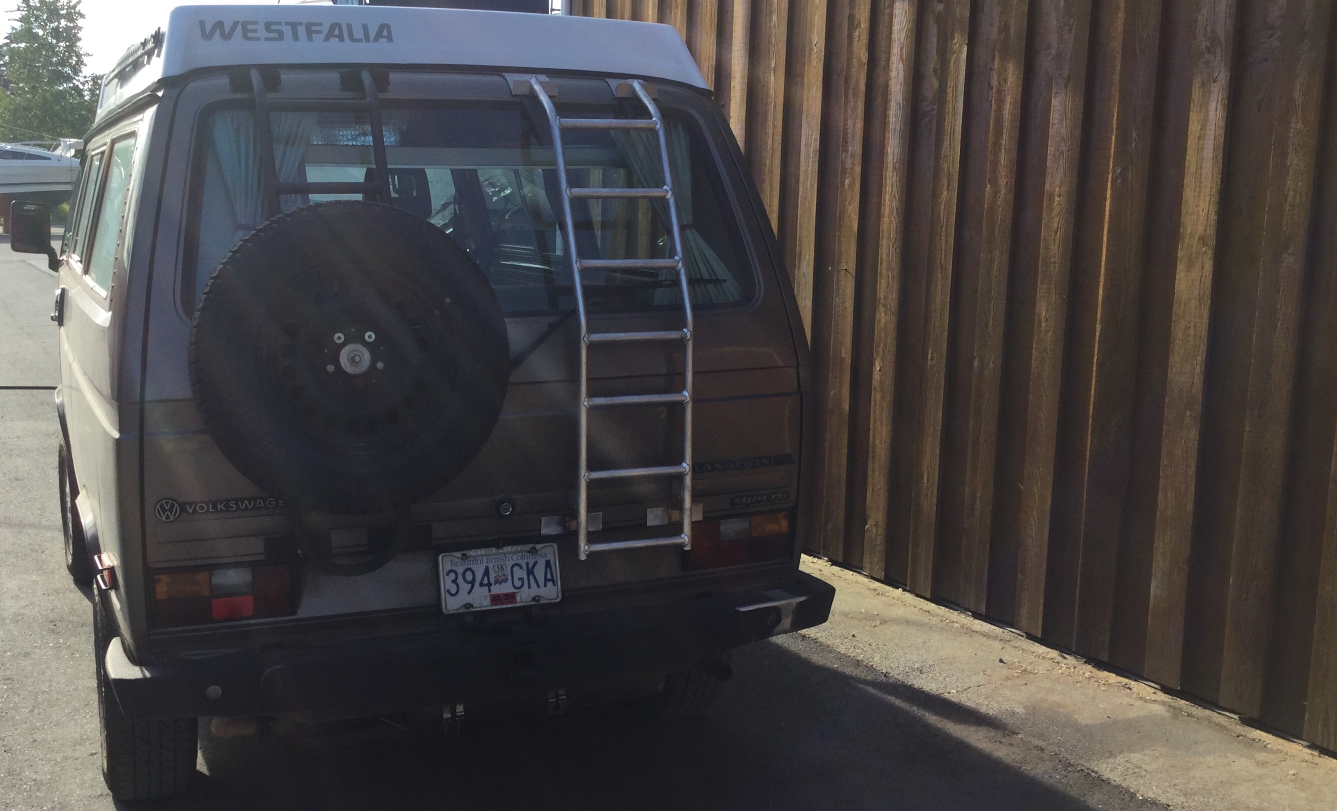
Still prototyping and fooling around. This one has more rungs. Perhaps more than you need but the request was for a tire carrier that might at some time be used just as a ladder. The tire carrier unit clamps onto a pair of the rungs, but only at one location.
That’s a stock 14″ rim on there, just to give an idea of where wheel sits.


.
Polish dividing head
Posted by albell in metal working, metalworking on September 3, 2015
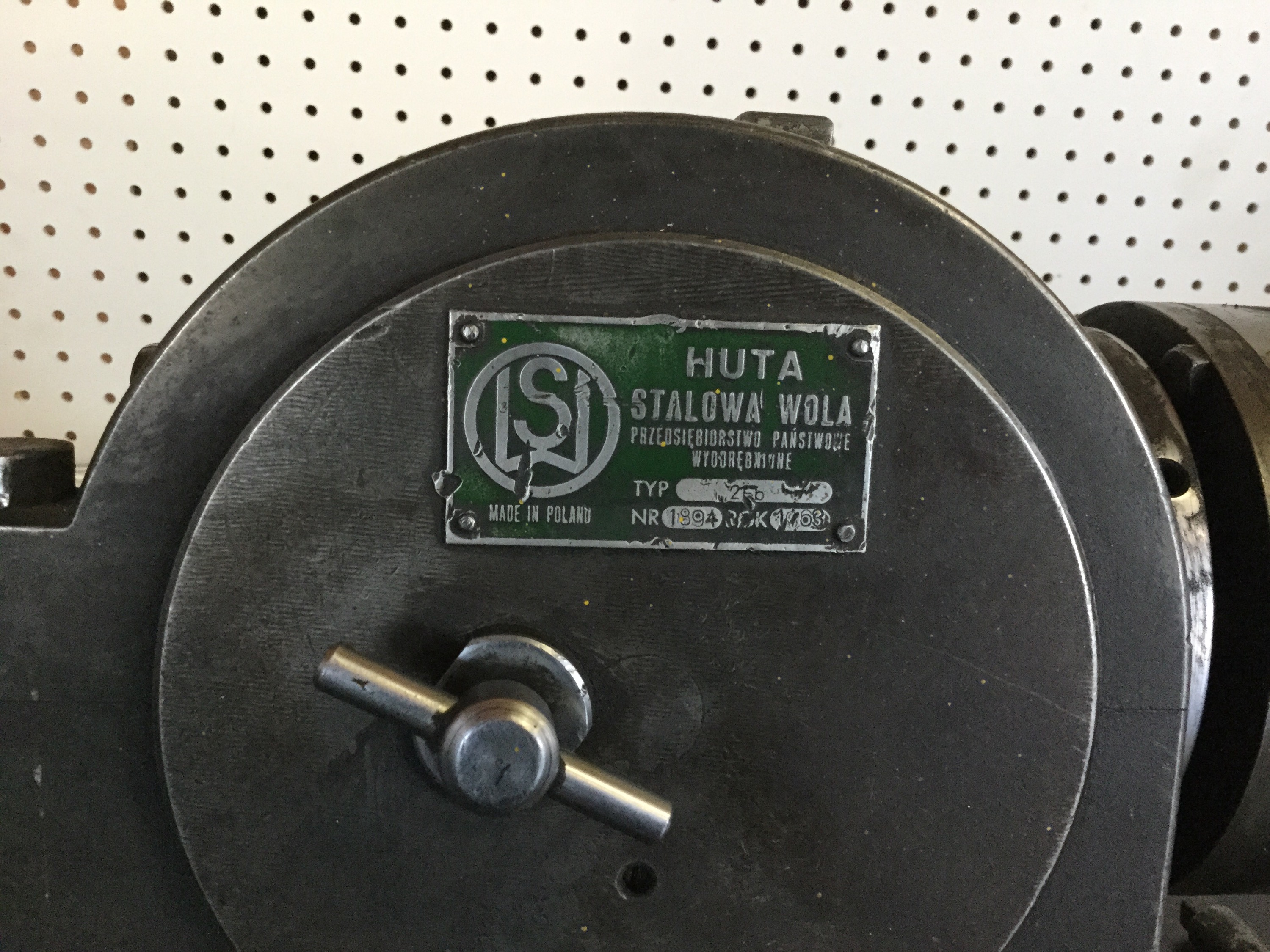
workplace purchase from recent auction at local metal work da Tory that went out of business, Ramsey Machine Works. No keen competition on the bidding on this item, I think we got it’d for 175 bucks. It looks like a very close copy of a cincinatti dividing head. It’s heavy, I can’t easily lift it and it take two to place it on the mill without bursting a gut.
Branded as Huta, nothing on the net about it, but the company was, or still is, an arms maker. Has the cool inner ring mechanism that I think makes 400,000 possible circle divisions.
I’ve used it already to make product. Cut the machining time down for a particular operation by… Well what took me an hour with my cobbled together jig now takes 20 minutes.
All old school stuff but so very cool. Btw, I just cleaned it up enough to use. Still needs some spit and polish ( no pun intended) but I don’t think I will be taking it completely apart any time soon.


Vintage shaper
Posted by albell in metal working, metalworking on September 3, 2015
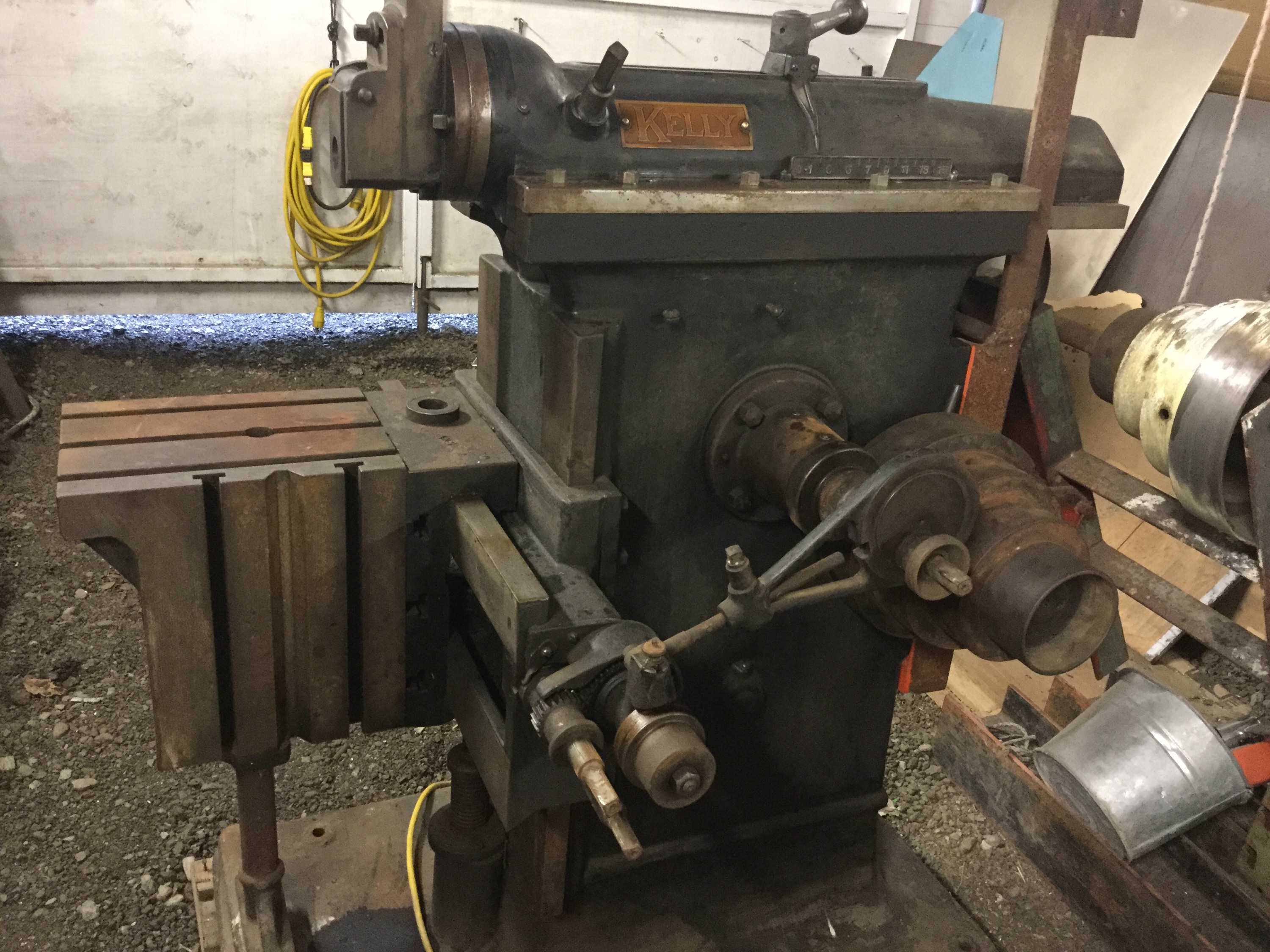
Got this beauty for scrap metal prices. It’s old, how old? I don’t know but I would guess early 20th century. It’s a little rusty but everything moves and I think I can get some flat belts, a sturdy electric motor and have it running. Even if it is only used to cut internal key ways it will pay for itself with the first job.


Taiwanese copy of a Kurt vise
Posted by albell in metal working, metalworking on April 1, 2014
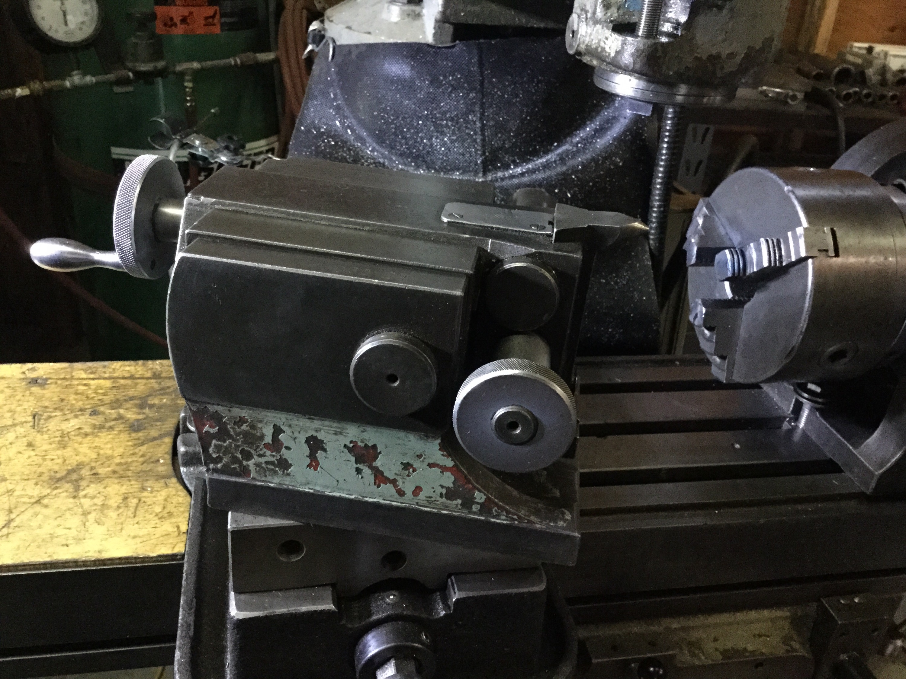
An old rusty bit of hardware was plopped in my lap the other day. It’s a STM CH-6 milling vise. Pretty well a direct copy of a Kurt. I didn’t think to take pictures of the state it was in when i got it, but did get some pics of the guts of the beast.
The claim to fame of the Kurt vide is the little gizmo in the sliding jaw that causes that jaw to push down when tightened on the workpiece. Kurt calls this “Anglok”. Here is a link to a pdf file of a Kurt vide that shows the Anglok feature.
Now the STM I was cleaning up does not exactly copy the Kurt, but does have the “Anglok” feature. Ok, now onto the pics…
The underside, yes it is a big bugger.

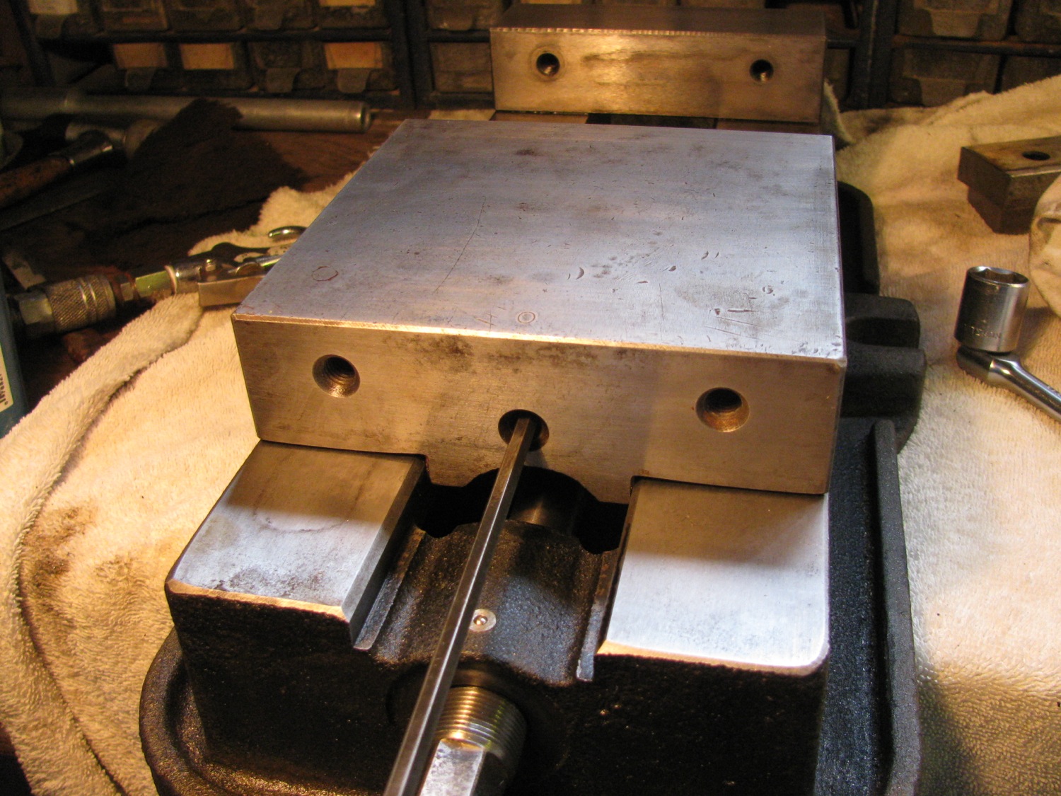
Yeah, I know most of you don’t have a clue what this next pic is showing. The underside of the sliding jaw showing the depression where the hemispherical part fits. This is the key of the “Anglok” idea.
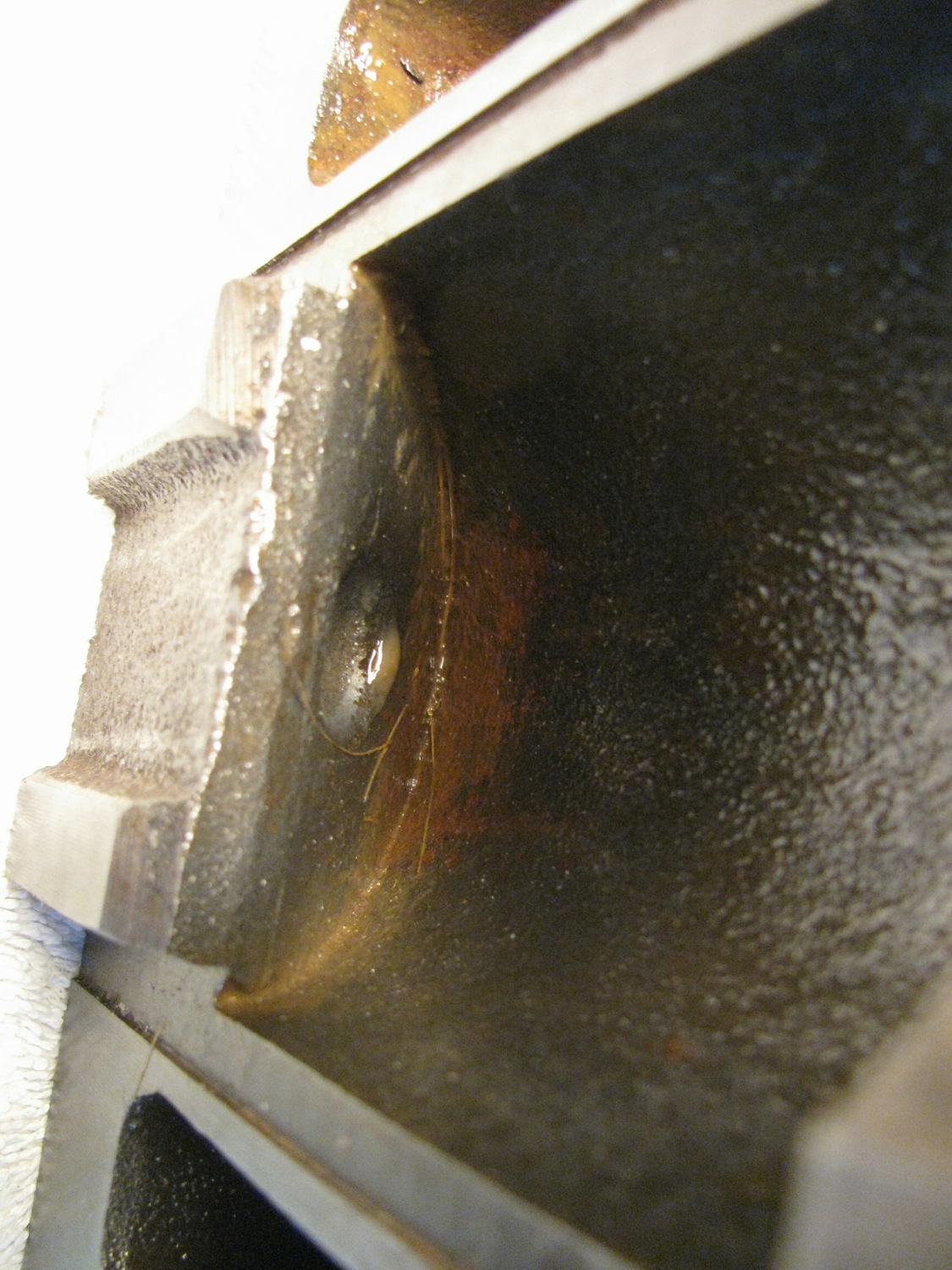
Aforementioned hemisphere.

Movable jaw removed. Look at the casting at the end of the screw, you can kinda imagine it has an angled face on the underside. That angled face presses on the flat side of the hemisphere. Also note the rust etching on the ways, where the jaw had been parked. The vide was sitting outside, getting oh so rusty.
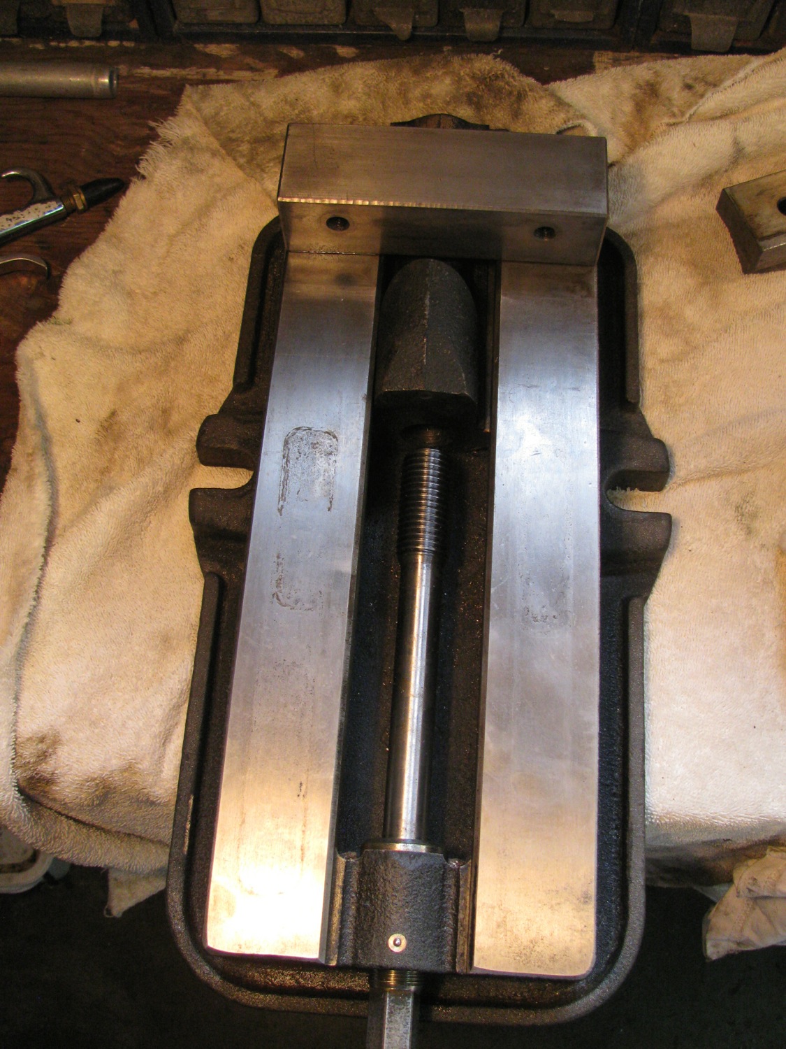
At the handle end of the screw there is a thrust bearing.

Oh this pic shows an allen key in the set screw that adjusts the free play on the “Anglok” system.
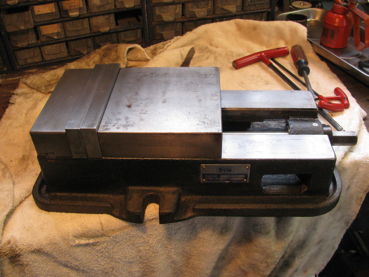
All cleaned up. apart from the rust, there was a lot of congealed cutting fluid and chips to get rid off. I was surprised that hit cleaned up as nicely as it did. It works smoothly, nice vise.
Vanagon – The “Swellegant” subwoofer
Posted by albell in metal working, metalworking, vanagon, vanagon mods on December 10, 2013
If your are sipping your coffee or any other beverage as you read this, please swallow what you have in your mouth and put the cup down. I’m not taking responsibility for any spit takes that might happen when you see what I made.
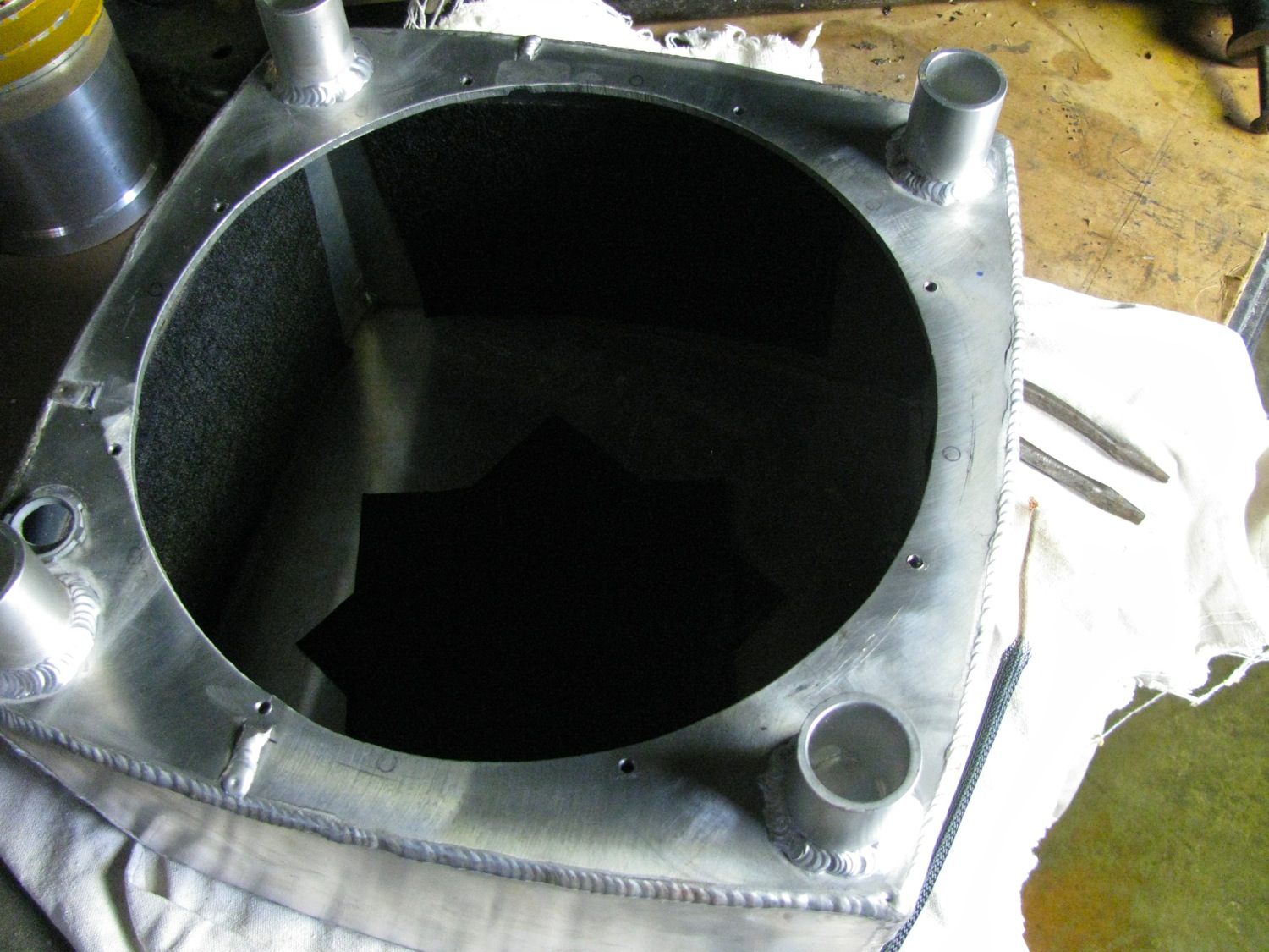
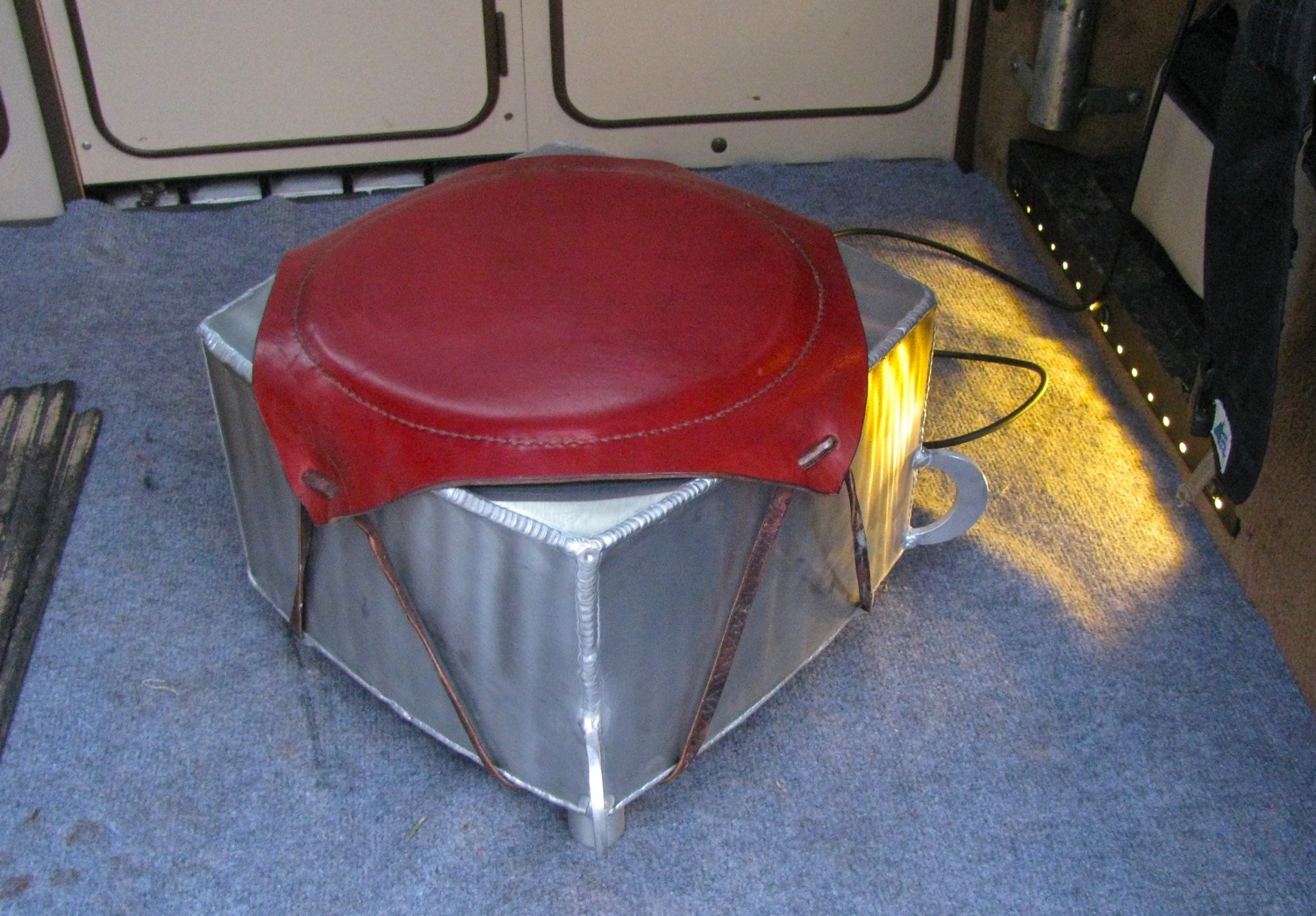
It started a couple of months ago when I was fooling around with some scrap aluminum and the TIG torch. I was adjusting the welding machine settings and rod size seeing what effect various changes had on welding outside corners. As I welded bits together I realized I could make a box of sorts and that would provide good practice on the seams. Well, i made the box, enclosed on 5 sides and I looked at it… what if I make it into a subwoofer enclosure?
3/16″ thick aluminum is not what springs to mind to use to make a speaker box, but what the heck eh? I had a pair of 12″ speakers in the garage, no idea what make, and I decided to use one as a sub. I added the 5th side to the box, actually pieced together from 4 bits, and cut a hole for the speaker. And why not four bits of tubing for legs? This was going to be a down firing sub. Oh and it was going to be a sub that paid very little attention to volumes, Q factors, etc, etc.
I drilled and tapped holes to screw the speaker to the box, than I made a grill from some 1/4″ square section material. The grill pleased me, stiffer than I expected. And just because I worried about how to secure the beast in the van, I welded on a couple of half moon bits to have something to attach a strap or something.
Ok, so it looked kinda bare. But I was recently given some leather so I thinks to myself “a leather pad thing on top would gussy it up some”. I cut a square of leather, a round of sleeping pad type foam, and some canvas as backing. I sewed it all together (and I found that difficult, only sewn a little bit of leather before and never saddle stitched) and attached it to the box with a leather thong.
And now it looks like some sort of industrial ottoman or commode. Go on, look at the pictures and laugh, I’m used to it now.
(Looking inside you might be able to see some dampening pads stuck on the walls)
Ta-da!
Yes, the sides are curved. Same scrap material that I made the underbody protection plate with.

Paper cone and still in one piece.

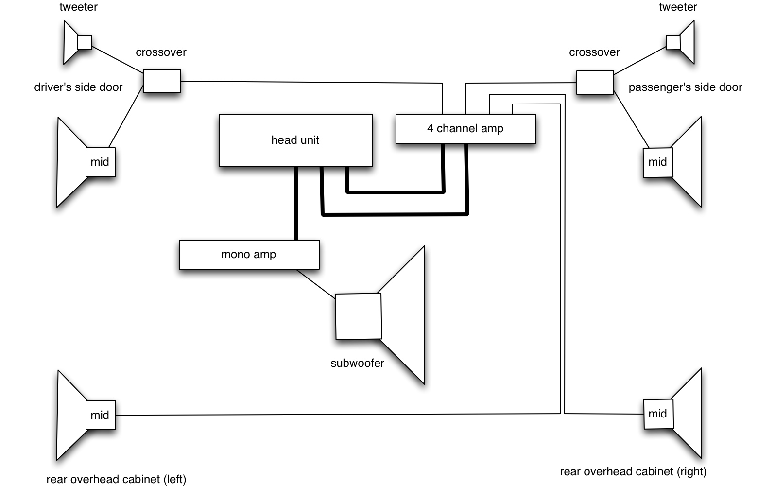
So how to power this thing? My head unit has 2 channel sub out jacks and I knew I had a spare amplifier in the workshop. An amp that was bridgeable so I could lead 2 channels in and have one channel (mono) out. I couldn’t find the damned amp, I searched high and low. Found all kinds of things (previous posts) but no amp. Good friend Stephen took pity on me and gave me an amp he had lying around. Nice old amp, a Blaupunkt 4 channel unit.

It was not bridgeable, but it excited me. The existing stereo set up in the van consisted of a Pioneer DEH-P5000 head unit feeding an Alphasonik PMA-2030 amp (not bad vintage amp) under the driver’s seat. That amp powered the front door speakers, Boston Acoustics Rally (model number forgotten) 6″ mid in lower part of door and tweeter up behind stock speaker grill. Oh and those are fed via some separate BA crossovers. Back in the rear overhead cabinet are a pair of 4″ pioneer speakers, powered directly from head unit.
I decided to pull the Alphasonik amp (not bridgeable) and use the Blaupunkt to power the front and the rear speakers. Was a little bit of a pain to do that, but I did manage to reduce the tangle of wires behind the dash (I can’t really fault the previous owners of the van, stereo installs seem to bring out the slipshod in all of us) and I squeezed the amp up on the crossmember behind the glove compartment.
That all worked well. When I say well I mean the stereo system still worked. But I don’t have my sub installed! Where the heck is that lost amp?
I found it the other day, not far from where it was supposed to be. It had fallen, or was placed (yeah, by me) in a box of fibreglass cloth and was covered by same. Callooh callay! I cried (no, I didn’t) when I found it. Some futzing and farting around and it was installed under the driver’s seat and finally my sub made noise. And what kind of noise? Well, a kind of thumping booming noise. It does pump out the bass, it does make things rattle, and once I fiddled with the sub woofer settings on the head unit (low pass and high pass filter adjustment) it sounded rather ok. I don’t think it is as tight or as controlled as a subwoofer should be, but considering everything about it, it is acceptable.
I have it connected to the amp via an RCA jack so it is easily disconnected and removed from the van. Right now it sits behind the passenger seat, but I can extend the cord and I might try other placements.
Oops, forgot, I made a quick sketch of the stereo system layout. Note the connections between head unit and both amps are via RCA jacked lines.
Vanagon – syncro – more underbody protection update
Posted by albell in metal working, metalworking, syncro, vanagon, vanagon engine swaps on November 4, 2013
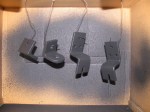
I’m trying to keep the momentum going, really I am. Over the last couple of days I got some work done on the side plate. The last post had me with the welded up, wavy and bent,skid plate. Now i had to mount it under the van. I didn’t think long and hard, but this is what I came up with.
A bit of 1″ X 0.25″ stainless flat bar cut up into 5 pieces, nominally 2″ long. Very nominally as I used a Zip disk in an angle grinder and I am notoriously bad at cutting a straight line.
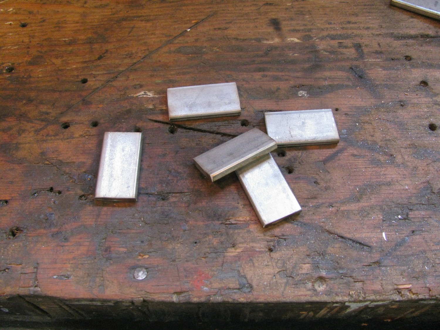
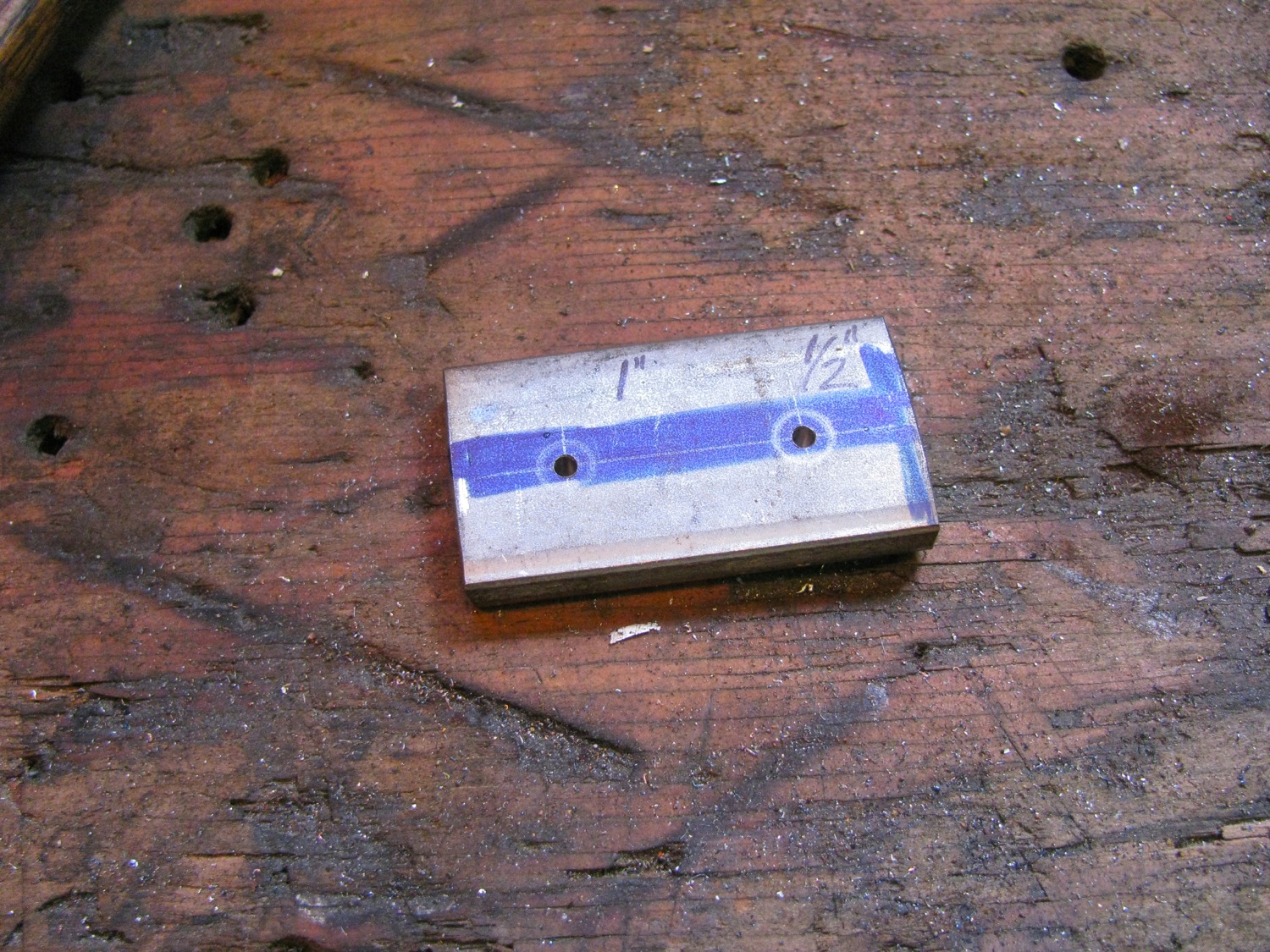
As each bit was more or less 2″ i marked out hole locations from one end. I used a blue Sharpie as lay-out dye. You can barely see the scratches of location the hole positions.

I feel presumptuous to lecture on how to do this kind of thing. I really am a ham fisted metal worker. I say that with no false modesty because I have seen what real metal workers can do. But allow me to go through the steps I take and maybe some of you might find something I say useful.
I scratched out the hole locations using my digital callipers. Then I centre punched on location using a cheap optical centre punch purchased from Lee Valley, direct link here. Then I like to make the punch mark a little larger with a regular punch. After that I drill pilot holes using a small bit, something less than 1/8″. The reason for that is the thin bit catches and hangs on to the punch mark better than a larger sized bit. I have the workpiece on the drill press table held in my hand. Allows the workpiece to move around a bit to get aligned. With a small bit there is little chance the drill will spin the workpiece around and gash your hand. With the size of holes I am drilling here, the next drilling step is the full sized hole. I’m drilling for a 1/4″X20 tapped hole and so I would be using a #7 drill bit (or something like 5.01mm). I put the part in a drill press vice for this drilling.
Now I try, in this blog at least, to avoid absolutes. But I am telling you now something you should heed. When drilling in stainless steel your drill bits have to be sharp and of good quality. Really, any other bits are just the road to perdition. What ever country of origin you like your bits to be from, buy the best you can. I think at one time nothing could beat US made made twist drill bits. But there are excellent bits from Australia, the UK, and Europe. Price is the discriminating factor, buy the most expensive you can find. It really is false economy to buy cheap bits (unless all you drill is wood).
A good resource for basic and advanced metalworking is Mrpete222 on YouTube, here is the link. And learn to sharpen your bits, might take some time, and god knows it took a good time for me to learn, but you can freehand sharpen bit larger than 1/8″ with good results. When drilling stainless a sharp bit is mandatory. If you see the bit is not cutting stop immediately and change out bits or sharpen. I use cutting oil, the sulphated kind, when machining stainless, I’d say it was mandatory to use cutting oil unless your only going through thin stock and then heading right over to the TIG welder and don’t want any contaminants.
Enough of the lecture, back to the project. The holes drilled then on to tapping. Same advice for taps, buy the best you can, cheaper taps work ok in soft metal, but in stainless and the like you need the best quality.
Poor pic of tap starting in hole.
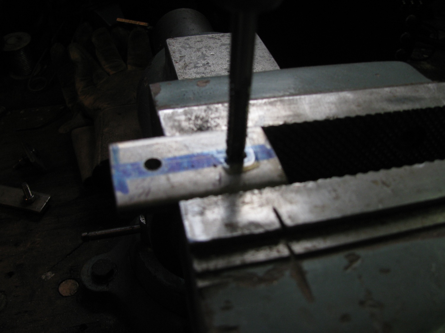
Then i held the parts in the vice and wailed on them with hammer to make a slight bend.

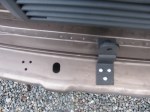
The threaded stainless tabs connect the new plate to the existing propshaft plate. I had to make the holes in both plates elongated to give me wiggle room to get things in place. And remember the new plate is curved and needed a bit of persuasion to get in place. I snapped this pic tonight, in the dark. The vertical part of the plate has not been fixed to the frame rail, it needs to be pushed up about an inch. but believe it or not, as is, it is quite secure and stiff.

I’ll get better pics tomorrow when i fix the outboard side to the frame rail.
Vanagon – more underbody protection
Posted by albell in metalworking, syncro, vanagon, vanagon mods on October 31, 2013
What am I doing screwing around with another project when I have a couple of unfinished ones on my plate? Well it’s just that yesterday’s propshaft protection plate build got me all hot and bothered to add at least one extension to the side. To the right hand side of the propshaft, between the skid rail and the frame rail, the coolant lines, the heater lines, and most importantly the shift linkage are exposed. You all know, but I’ll repeat, the shift linkage is protected by a tube on 16″ syncros, regular syncros with the bad road package, and ’91 (maybe ’90 too?) syncros in North America at least. The tube protects a couple of the joints in the linkage and I think that is a very good thing. In the winter I have had slush and ice build up on the linkage such that the van becomes hard to shift. Rather than try and reproduce the stock protection tube I thought that a plate over that entire section would be the ticket.
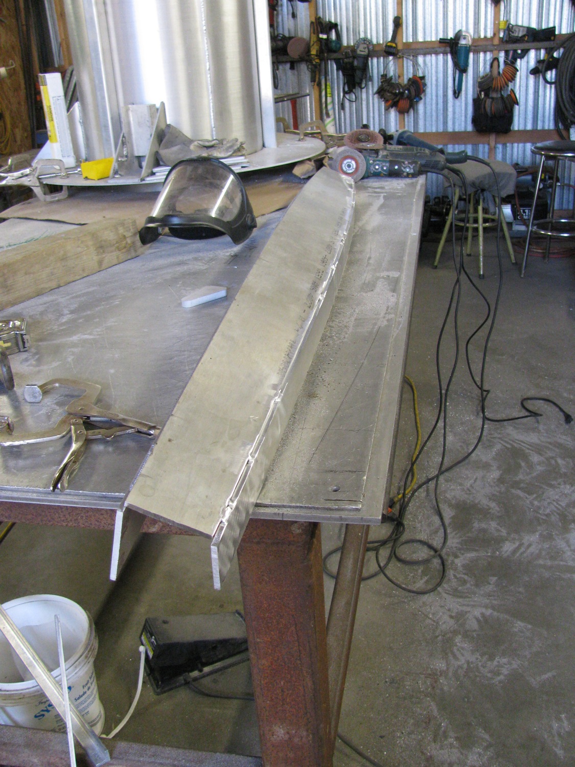
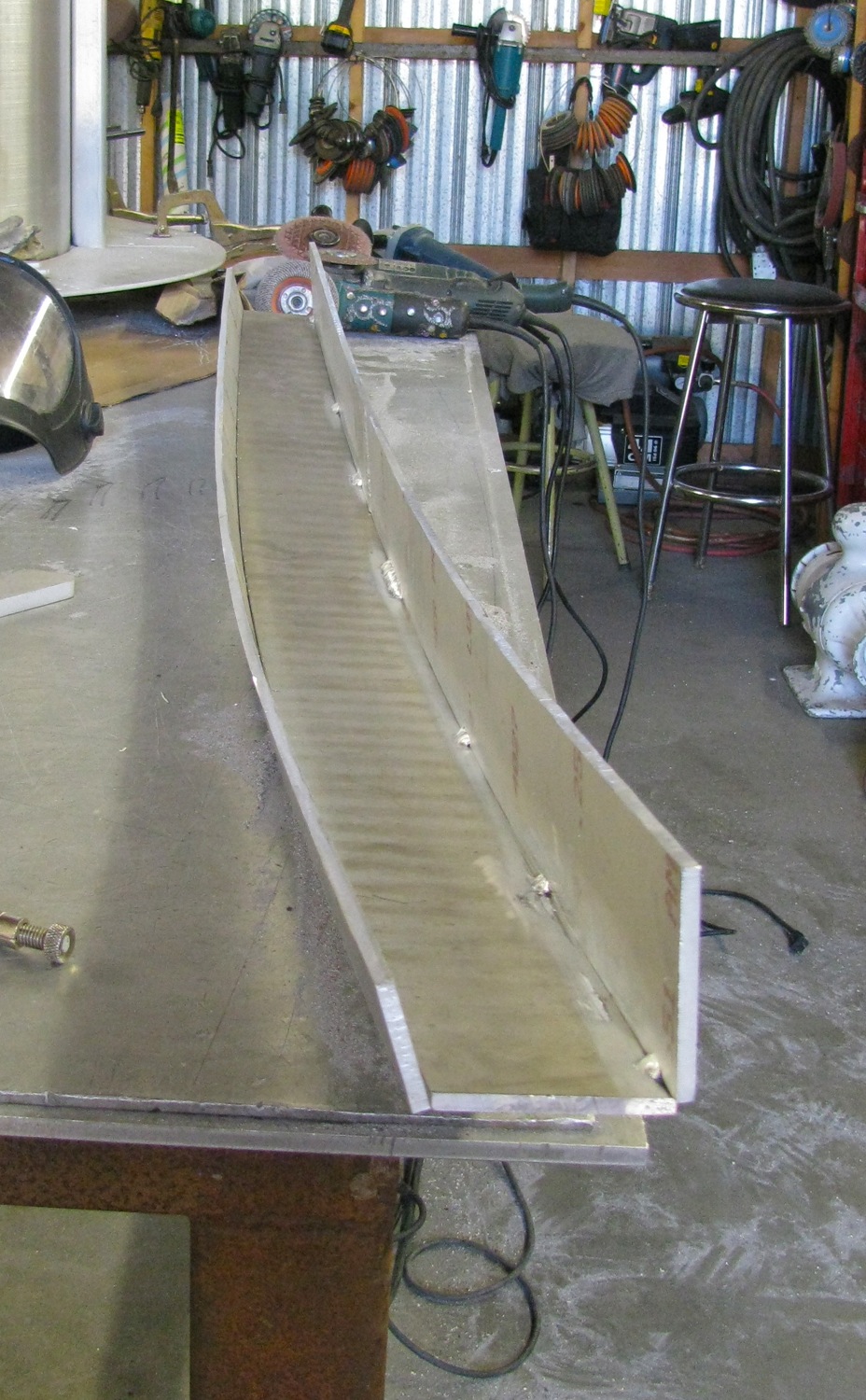
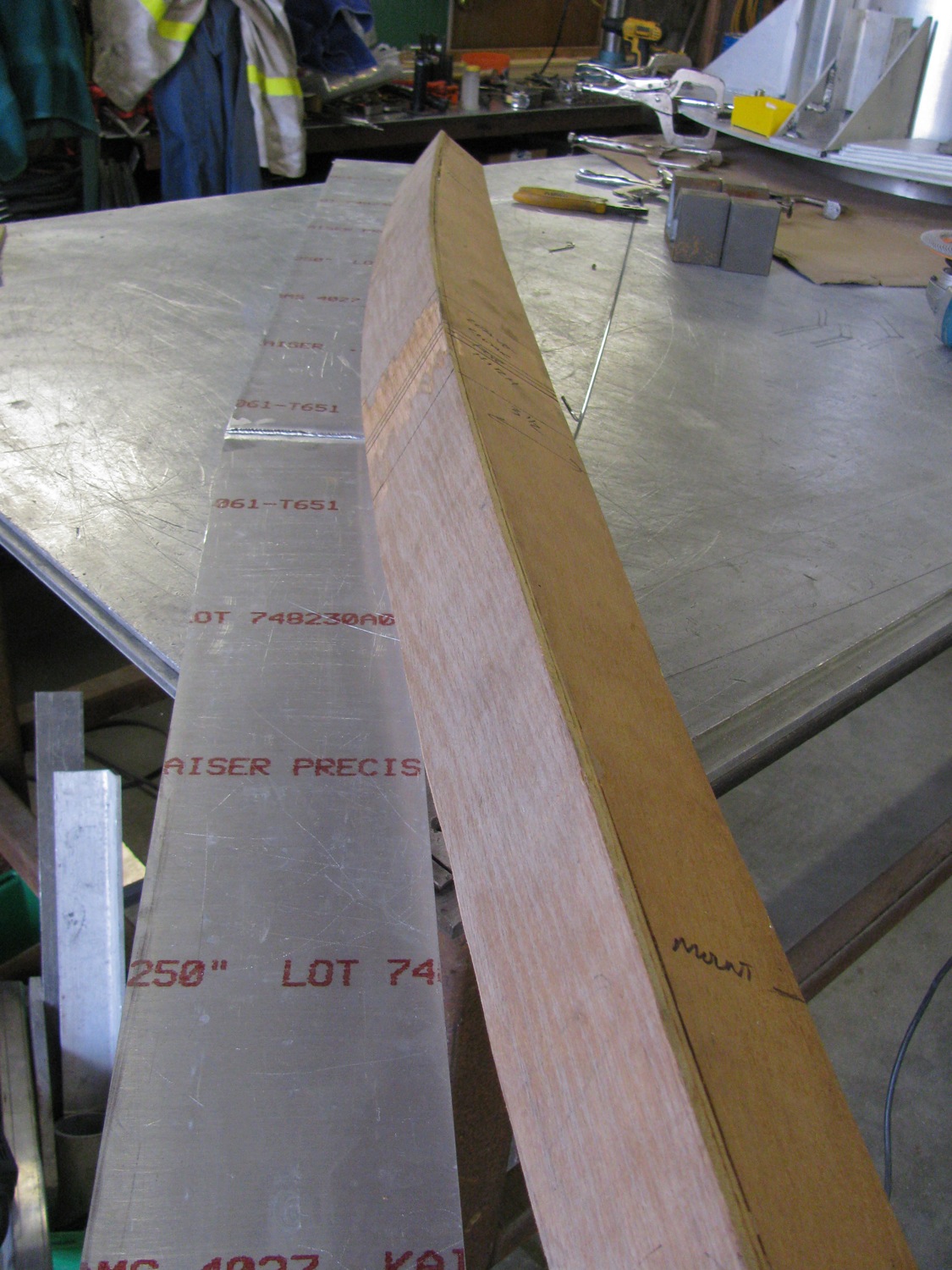
I needed a bit of stock roughly 11″ X 53″. I couldn’t find anything in the scrap pile that size so I had to do it the long way. Got these cut offs, bent, 3/16″ 5052 aluminum.
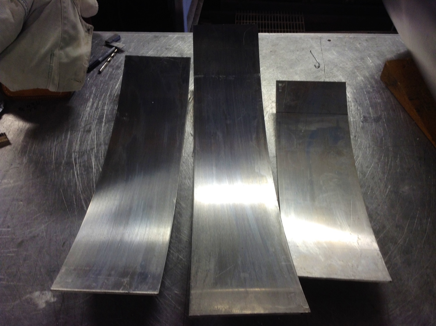
I cut them up.
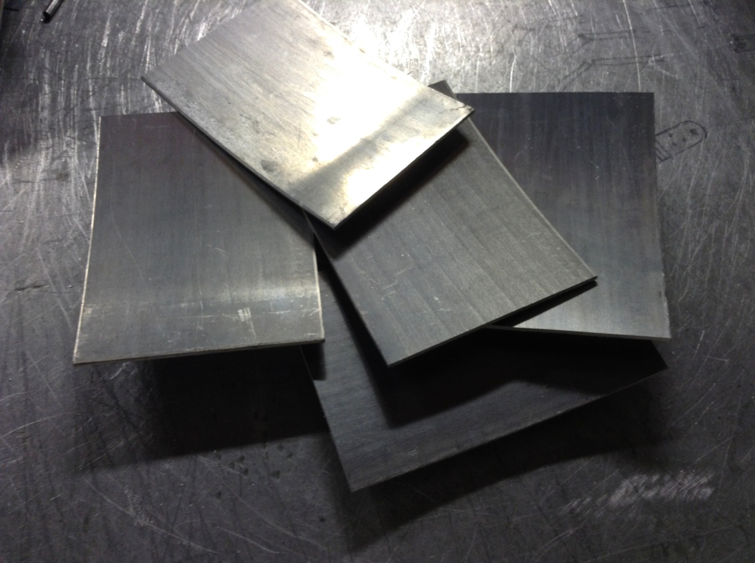
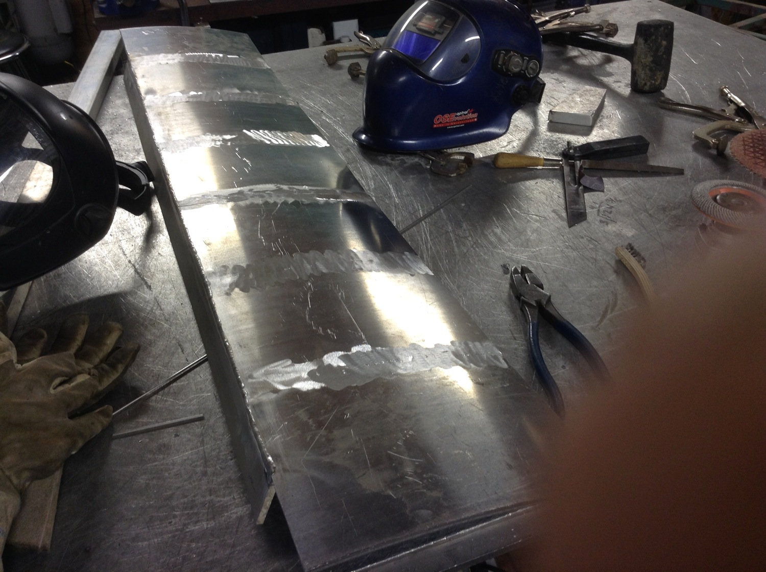
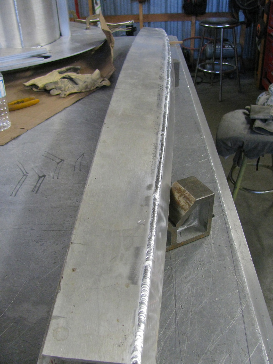
Then tacked them together. I welded a length of 1/4″ X 2″ 6061 along one side, welded out full on the concave side, then back gouged the convex side.

Welded out those grooves and ground the welds flush. The welded up assembly, and no points for guessing this, did take a curve. I laid a little beatin’ on it but accepted the wow. I think I can make it work for me and pull it out somewhat in the install. Is that my thumb in shot? I was using the iPad to take the pics, left my point and shoot camera at home.
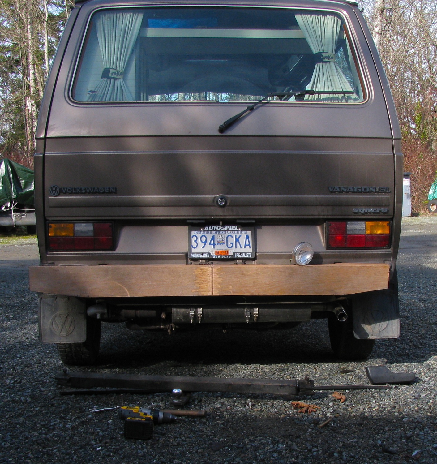
Clamped it in place on the van, to see what’s what. BTW, my welding was shit today. I had a lot of oxides bubbling up, never did get in my groove. Maybe it was the old stock I was using or maybe I was not on the ball.


The outboard edge will sit a little higher on the frame rail, I just couldn’t clamp it that way. You know, the curves in the beast makes it stiffer than you’d expect. Now I have to make a few tabs to mount the inside edge to the propshaft protection plate, and I’ll bolt the outside vertical section to the frame rail (there are holes already in the frame that I can use).
Vanagon – iPad mount – MkII
Posted by albell in metal working, metalworking, vanagon, vanagon mods on August 29, 2013
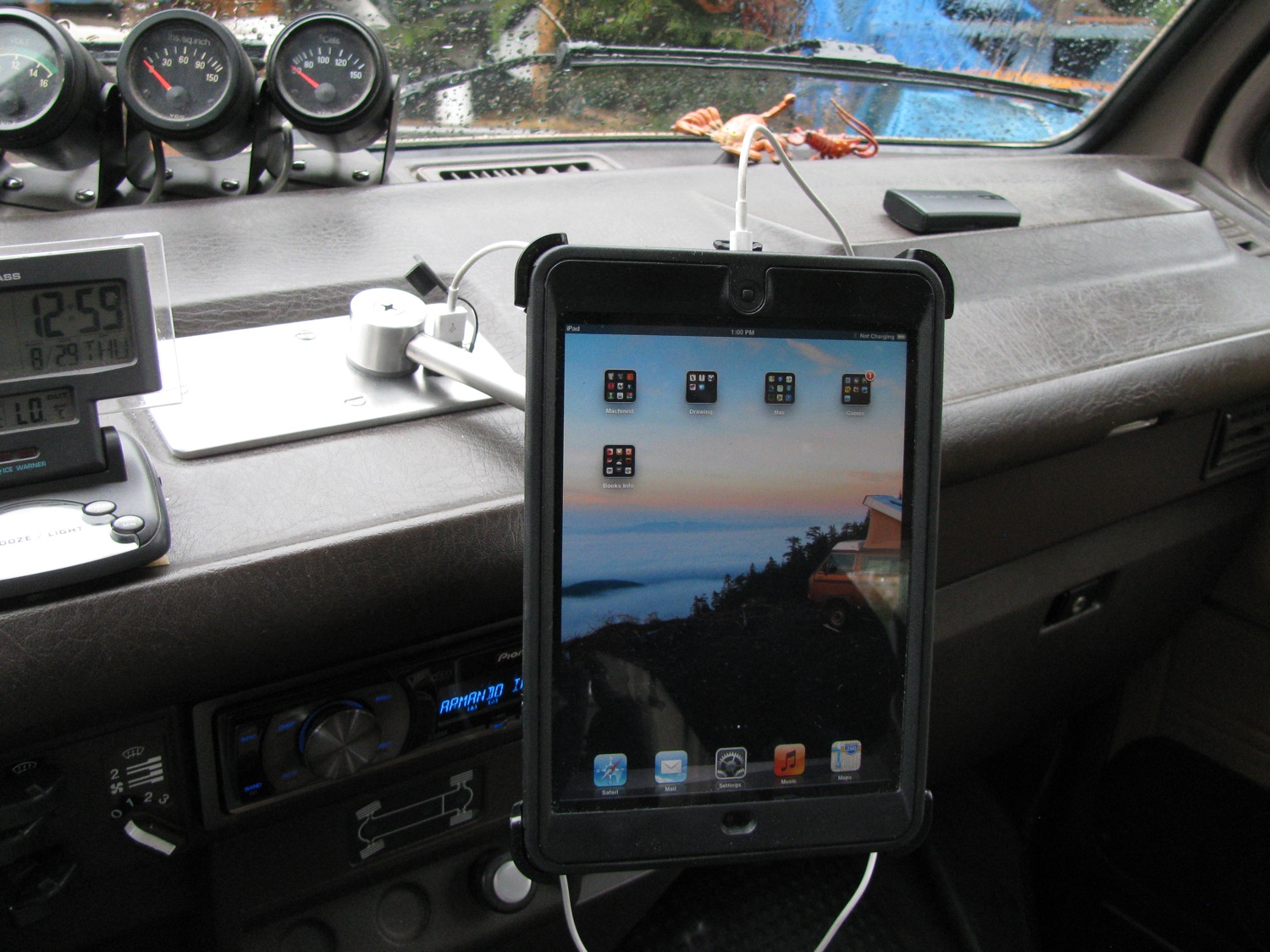
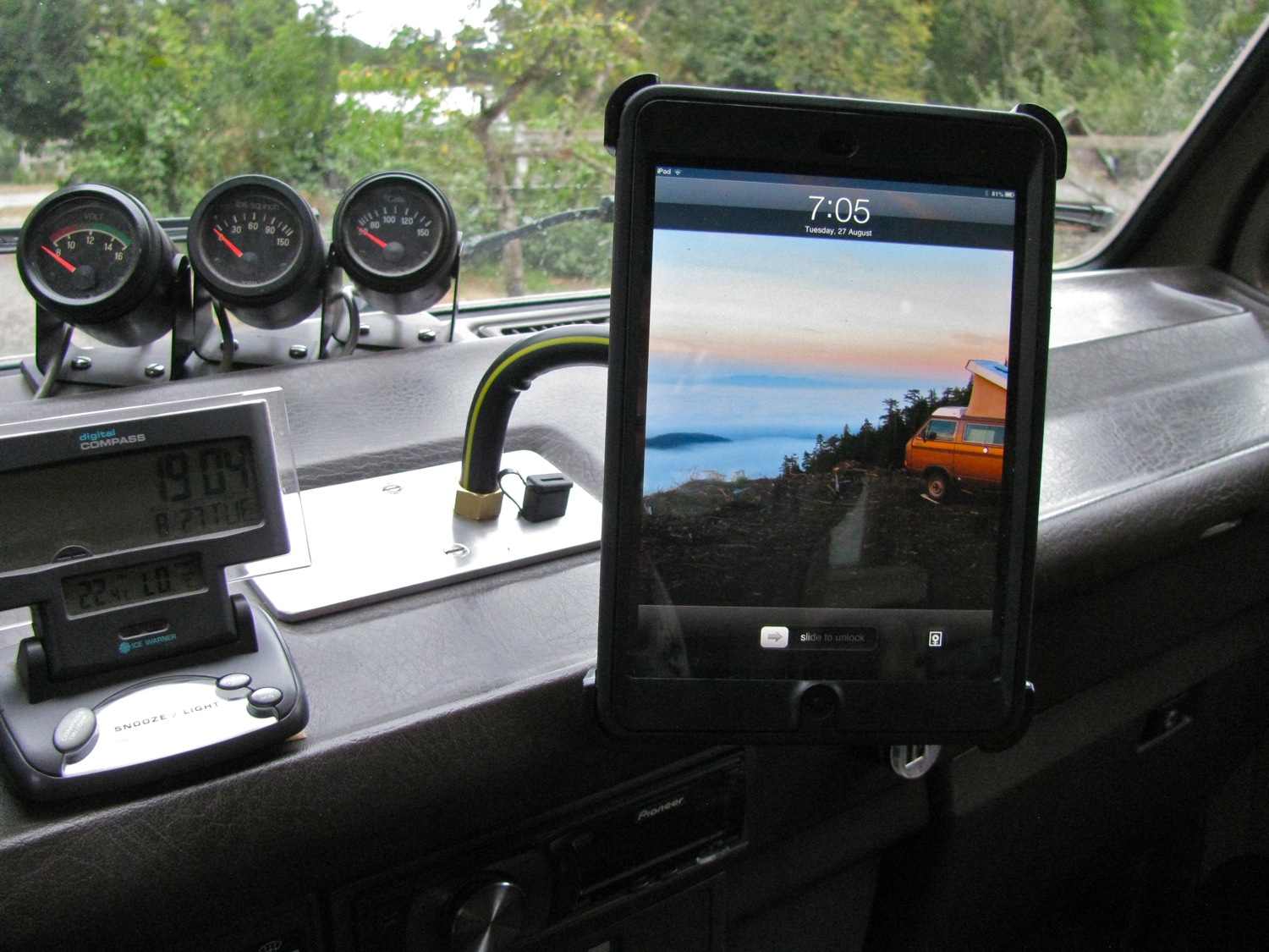
At the end of my last post, the beginnings of a trailer hitch, I showed 2 pics of my iPad Mini mounted on the dash. It was a start, a Mk I if you like, to see if I liked the position. I used some found coaxial wire, about 0.6″ diameter, aluminum wire core, polyethylene, aluminum sheath then vinyl cover. Or something like that, the point is the stuff bends and holds. It doesn’t bend back and forth forever though. Anyhoo, that and a swivel mount I made (aluminum and teflon on the moving parts), some plumbing fittings, and a pretty crudely made plate on the ashtray hole.
I did try mounting to the inside of the ashtray, and I managed to do it. But the ashtray wouldn’t stay in place with all the weight and I broke the damn thing trying to solve that problem.
I didn’t like the high position of this mount so back to the bench. More bits of scrap aluminum, some 0.5″ stainless tubing, and further dicking around ended up with something that looks more surgical than automotive. Man, I need some sense.

The swivel mount has some Velcro on it. I’m using that to connect to the Otterbox Defender case (the cover part that doubles as a back and a stand). Velcro is not great for this, but was all I could come up with for now.
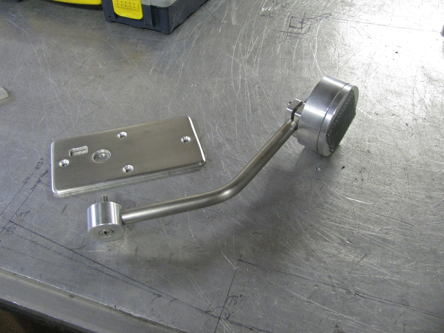
Crude tabs to hook into dash. USB extension cable for connection to stereo head unit.
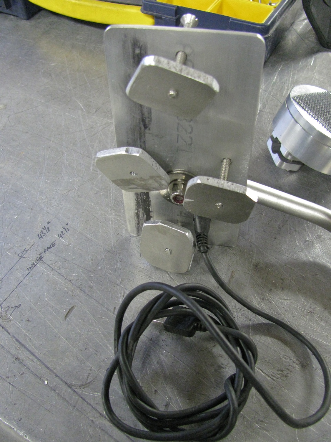
I made the arm a bit too long, I’ll trim it back. I like this position better and yes, you can still shift gears.
Swivels to landscape.

I agree, it is a bit clunky. And what to do with the cable? I don’t want to run it inside the tubing. Maybe I can figure something out to make it less untidy looking.
vanagon – bumper build – starting the hitch
Posted by albell in metal working, metalworking, syncro, vanagon, vanagon mods on August 27, 2013
I’ll blame good friend Simon for the recent dearth of posts, you might understand why at the end of this post. The bumper is pretty well roughed out and before I can finish the aluminum I need to make a trailer hitch to fit behind. I do have one of those tow loop mounted hitches but I want something stronger.
So the idea is a receiver style hitch with a crossmember behind the bumper welded to the stock bumper mounts (which I will modify and extend further I the frame rails), and the receiver part of the hitch coming through the lower part of the bumper. I’m not being very clear, sorry, it all make sense as I post my progress.
And what progress have I made? I’m going to pad out the little work I have done.
Well, here is my existing hitch and the bits for the 2″ receiver.
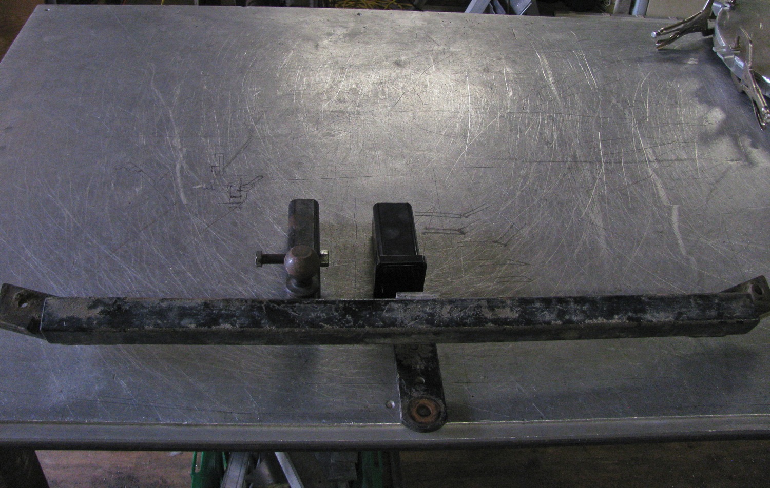

I cut the bits off.
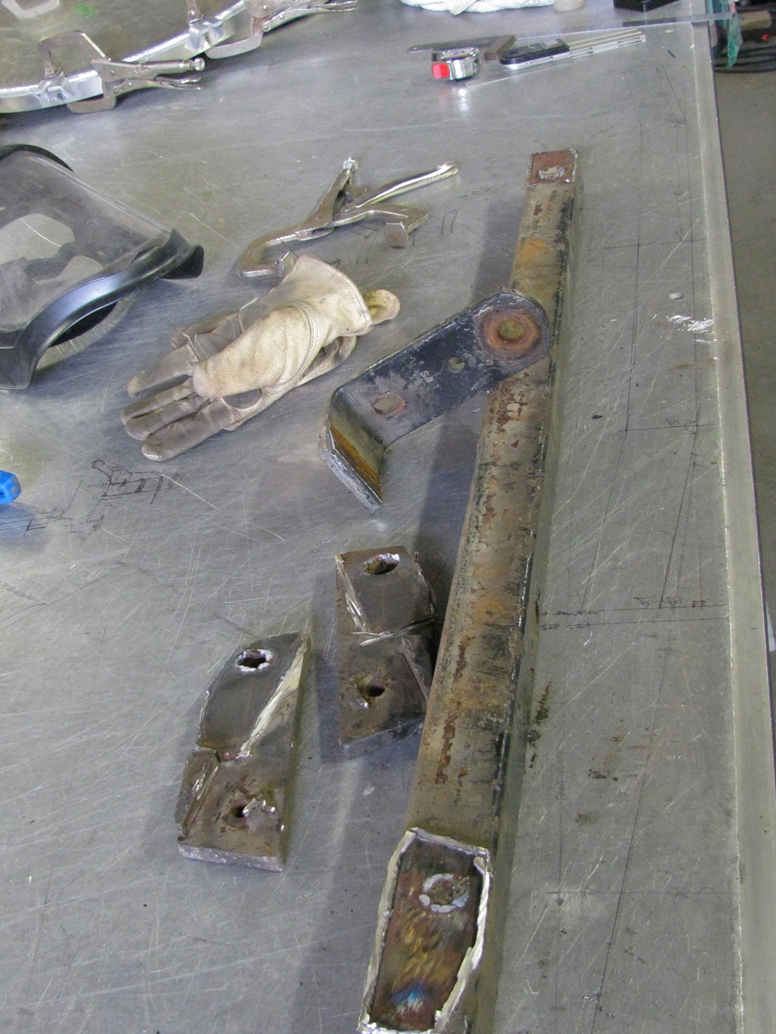

I want to have this bar sit as close to the inside rear face of the bumper as possible, To do that I need to make a couple of bends. Pretty sloppy work cutting “V” notches to make a 7 degree bend, I could have done better. Oh I did cut the tube in half before I did the notches.

Up it bends, leaving a big gap, grrr.
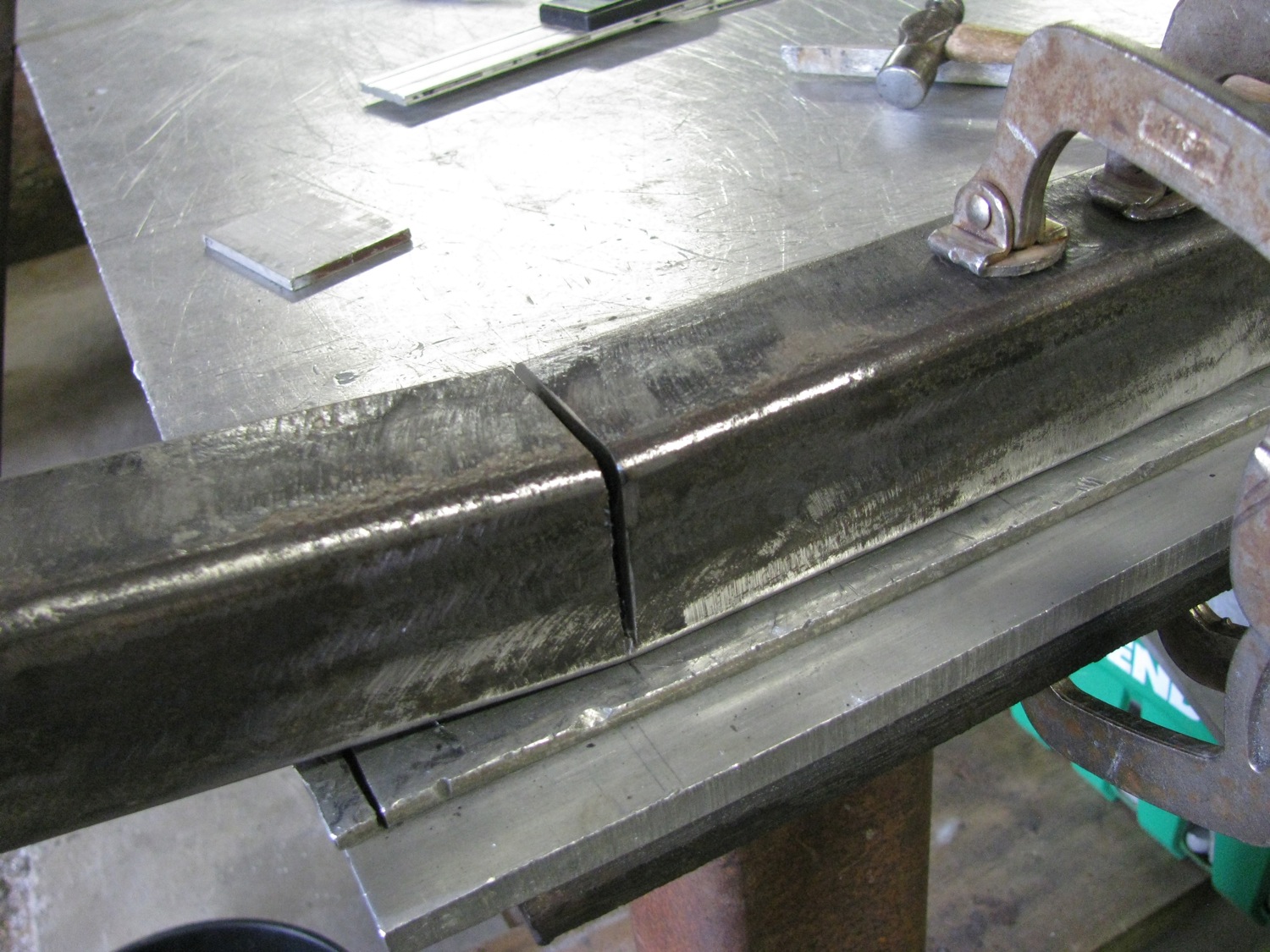
Get the idea of what I am aiming for?

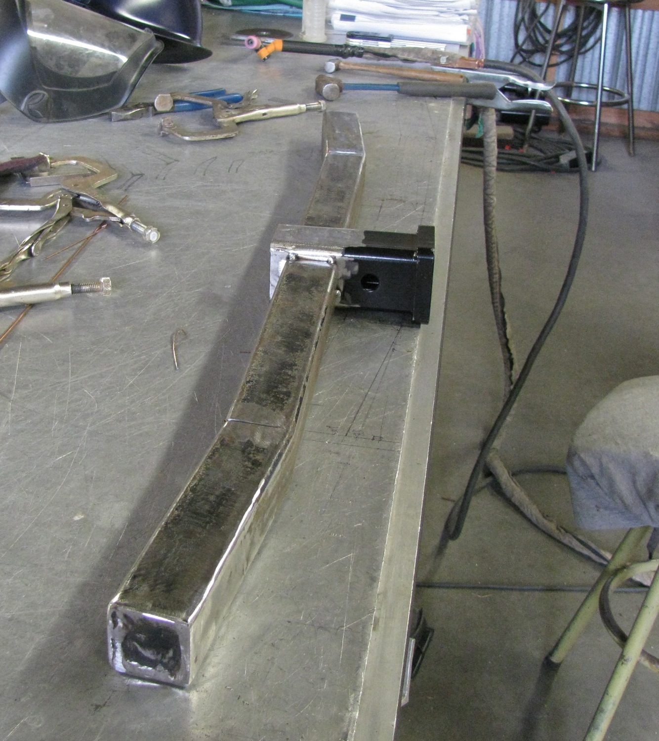
It might come as a surprise that I can’t stick weld very well. The MIG welder is set up for aluminum and stainless and very likely will never see steel. So until my welding teacher comes by to give me some stick welding pointers I TIG tacked the bends and other parts onto the tube. I used some rod to help me jump the gap with my tacks.

All tacked up and ready to start trial fitting to van and new bumper. Oh, btw, I will add some reinforcing plates between the receiver and the main tube.
So why is Simon partly responsible for me not posting more often? He gave me an Ipad mini. Yup, what a guy. I’ve been playing with navigation/map apps and I think I might post some stuff on that. Also started mocking up a mount to install it in the van. It’s a start, by no mean the final thing, but gives me some ideas.
Thanks again M&S.

Vanagon – bumper build – other end cap done
Posted by albell in metal working, metalworking, vanagon, vanagon mods on August 9, 2013
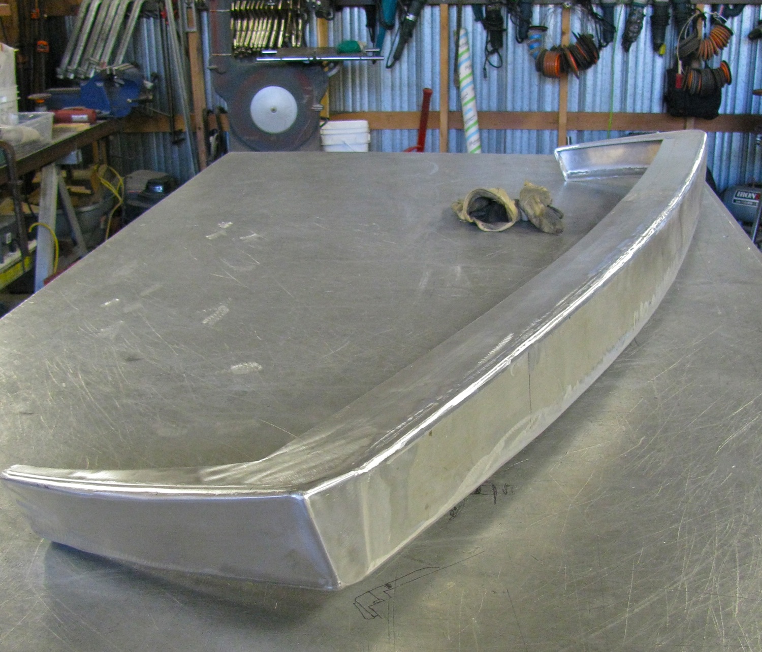
Update: I weighed the bumper as you see it below, it’s 9.2 kg (20.3 lbs). For comparison, the stock chromed steel bumper, minus plastic end caps, weighs in at a svelte 5.6 kg (12.3 lbs)
A little progress made on this project. Made up a more or less matching end cap and also did some preliminary grinding out of the welds. What a chore this way of making a bumper this is. You understand don’t you, that this is me making it up as I go along, modelling (I can hardly say sculpting can I?) a bumper out of aluminum plate. Once I get a shape that I like and that works then I can take measurements and think about how you could make one easier and faster.

Vanagon – bumper build – fixing the endcap connection
Posted by albell in metal working, metalworking, vanagon, vanagon mods on August 7, 2013
I really didn’t think through the bumper to endcap transition did I? Here is what my doodling around resulted in.
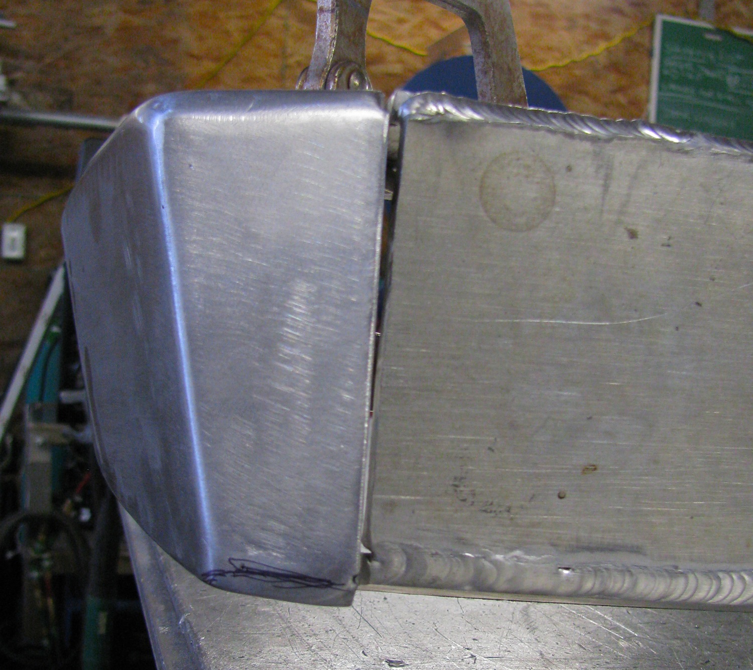
I have to be clear and say again that I’m winging it. I’m doing in aluminum what I should be doing in cardboard or thin plywood. So to fix the blunder, I cut the endcap up a bit, angled the bottom plate to match the bumper bottom plate, added another filler piece then welded it up and roughly smoothed things over. It is a lot better now, this might be the one to keep.

I didn’t take too much time grinding the welds, but enough to get the idea of how I want the corners to look.

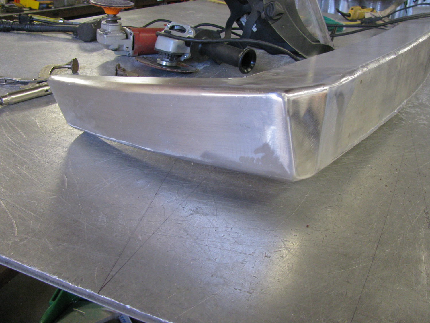

Both bottom plates, bumper and endcap, meet up a bit better. I’d like to radius or smooth out the inside corner also.


Next thing to do is to double check fit on van, smooth out some wavy edges and corners, then make a matching (ha!) endcap for the other side.
Vanagon – bumper build part 2
Posted by albell in metalworking, vanagon, vanagon mods on August 1, 2013
I managed to tack and weld out the 3 main parts of the bumper. It was a little bit of a struggle pulling the bottom plate into position (inside edge to inside edge with about a 1/16″ overlap). I ended up TIG welding all the joints. I didn’t like the MIG welds I made on a test piece (I don’t have many hours on the machine). I’m not saying that my TIG welds are very good, but at least I got some practice. In any case, I’m going to grind down the welds to make a rounded or at least a beveled corner. I haven’t finished fairing the free edges of the top and bottom plates yet.
Tacked up.

Outside tacks on the face to bottom plate joint.
Inside tacks on top plate to face plate.
Then on to my inconsistent and amateurish weld out.
All done, top and bottom plate welded on.

I’m rubbish at estimating weights, but I’d guess around 10 kg as is.
Vanagon – rear bumper build
Posted by albell in metalworking, vanagon on August 1, 2013
I figured I need to post what I have done so that I have more reason to finish the job. I want to make new bumper, front and rear. Not because the stock bumpers are damaged or rusty, but because I want bumpers that are a bit stronger and will be able accept a spare tire carrier on the rear and better aux. light mounts up front. And just because I want to make some bumpers.
It’s a project that never seems to get really going nut here is the progress to date.
Last year I fooled around with making a mock up rear bumper out of door skin and hot glue. I came up with a shape that to be honest was the best I could given the brief of it being simple, slim (not bulky like some aftermarket bumpers – yes, I’m looking at you Go-Westy) and easy to make. The door skin and hot glue construction makes it easy to add or remove material and have a relatively solid model to play with. I have a hard time visualizing an object from drawings so I tend to make a mock up (or remake the real object).
I started with a slim bumper design, very simple with a flat top surface (to make standing on bumper easier), a gentle curve on the rear vertical face that closely mimics the stock bumper, and a curved lower edge rather than straight lines to where the bumper caps would be. I took the first design over to let Simon have a look. His tastes lean a bit more towards a heavier bumper so I stuck on more door skin and made it so.
BTW, in the mock up pics the bumper is shifted to the left due to interference between the stock bumper mounts and some wooden braces in the mockup.
I don’t like this at all.
I removed some wood, looks better. Probably would please Simon.

But I like ’em slimmer still. Ended up back to the original shape.

Right then, I’ve settled on the rough shape now what material will the real bumper be made from? Silly question, aluminum naturally. I’m using some off-cuts of 1/4″ aluminum plate (6061). I think that thickness will be plenty strong, especially when it is bent and welded up into the final “C” channel of the design.
I should mention that I took dimensions from the mock up and “projected” the 3 faces onto the top of the workbench. I used a bit of wood to fair the curves and picked up the shapes for the 3 main parts (top, bottom, rear face)h onto some polyethylene sheet. I could then tape the pattern onto the aluminum stock and use a prick punch to mark the shape on the aluminum. But I’m getting ahead of myself, I have to weld some of the aluminum together before cutting out the shapes.
My lumpy and large TIG weld. In my defence, I hadn’t touched the welder for a couple of months so what little skill I did have seemed to have slipped away.


I’ve cut out the 3 main parts, rather roughly I’m afraid, and if I have time today I’ll try bending and tacking them up. I’ll need to make some internal braces just to make the weld up easier. I’ll TIG weld the tacks, then I think I’ll use the MIG welder for the final weld up. It would be sort of silly for me to TIG the long welds.
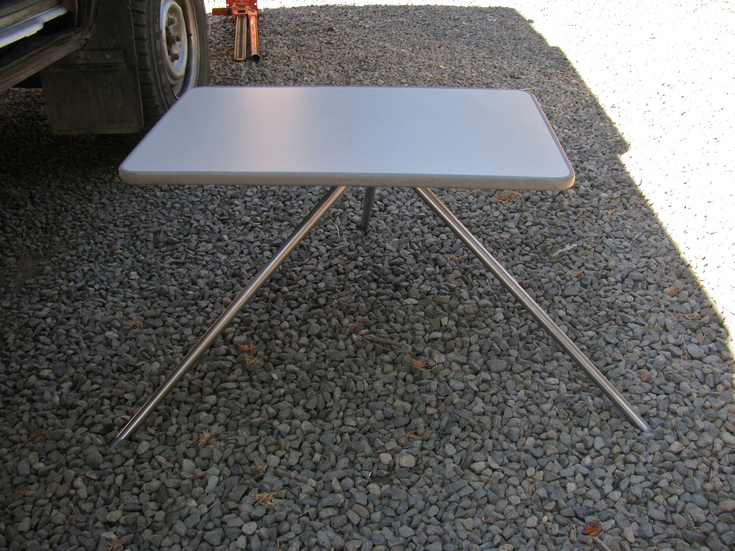
Vanagon – front table stand
Posted by albell in metalworking, vanagon, vanagon mods on July 21, 2013
From the same twisted R&D department that brought you the “Excelsior” toaster, comes this slightly silly stand for the Westy front table. It is kinda nice to have a low table beside the camp chairs, something to put your drinks and snacks on. One could modify a cheap camera tripod to do the same thing, but when one of those tripods are set low they don’t have a heck of a lot of stability. A box works well as a support, but really, that’s far too practical and sensible.
Again, made from scraps – 6061 aluminium, stainless bolts, and some Delrin. The leg to hub connection does look a bit weak, but if it fails I’ll go from the M8 threaded stud to a M10. You would be right thinking the 3/4″ diameter legs, at that angle, put some strain on the connection to the hub. But the open ends of the legs dig into the ground and stiffens things up.
Table sits about 16.5″ high.
Yes, I could have, maybe should have, female threaded the base of the hub so it could be left attached to the table and the stock “leg” in the van could screw into it. That was too much work to do 🙂
Oh I should mention this is a front table from a later year Westy. The older version has a short section of pipe sticking down from the table.


Vanagon – muffler update
Posted by albell in metal working, metalworking, syncro, vanagon, vanagon mods on December 13, 2012
I got the final end cap welded on today, not the neatest tig weld due to my poor cutting of that end of the can. No filler was used in the weld, just flowing the parent material. I gave the muffler a quick once over with a cup wire brush on the angle grinder. I think this is as far as I am going with the finish, I don’t see myself holding the thing up to the buffing wheel for a couple of hours.
The pics show the muffler sitting on some aluminum off cuts ( I have access to a lot of interesting shapes in various thicknesses of aluminum, remnants from water jet cutting of work parts). These scrap bits had curves to match the radius of the muffler. The scrap is clamped to a spare engine mount casting so I can see how I need to move things and what metal to remove. I’m leaning towards the aluminum supports (yes David, there will be electrolysis where the ss and Al touch:)) with some T-bolt ss straps holding the muffler tight.


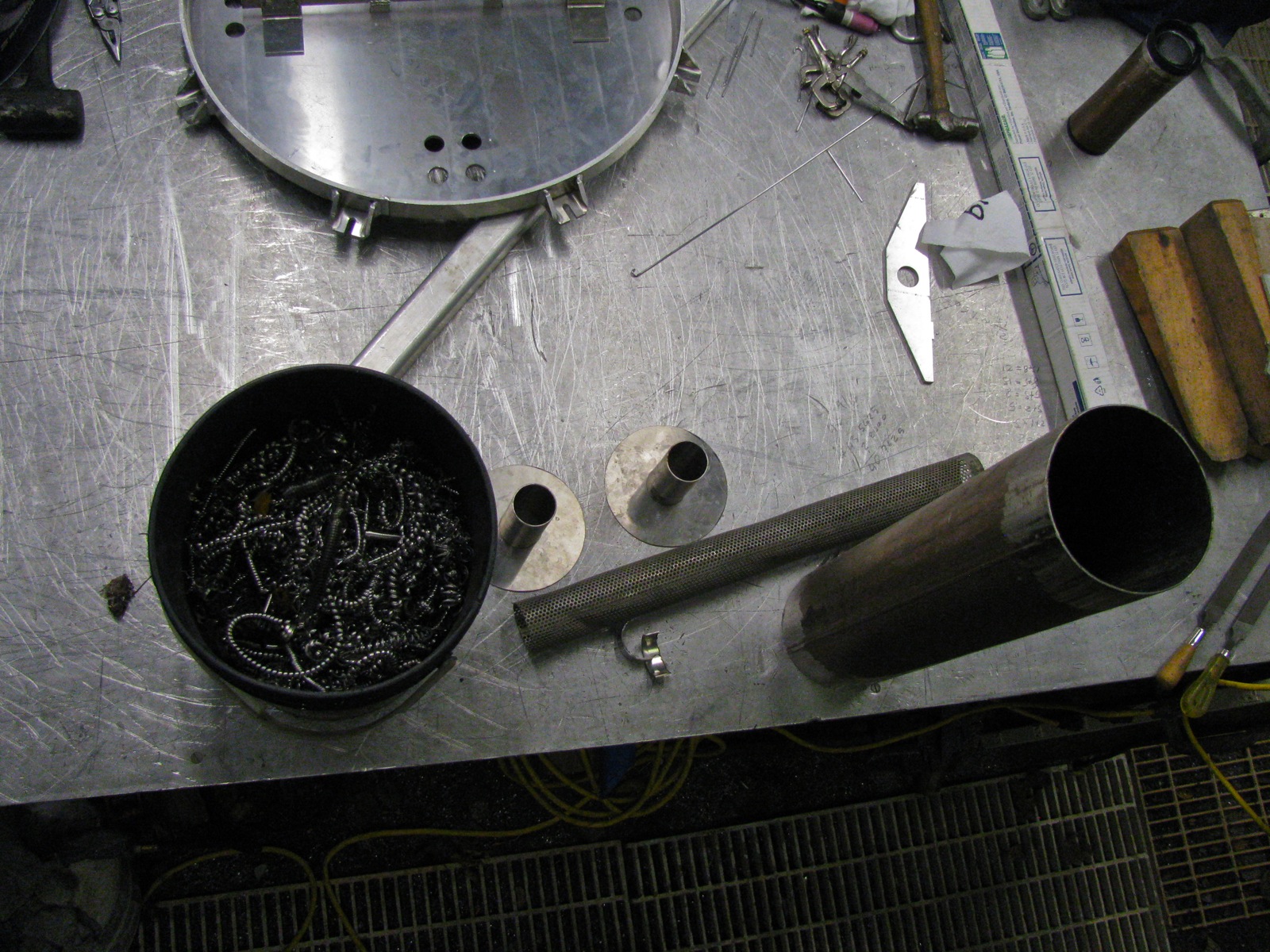
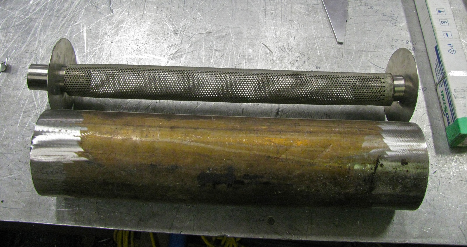
Vanagon – making a muffler
Posted by albell in metal working, metalworking, vanagon, vanagon mods on December 4, 2012
As if I don’t have other things to do, I’m making a muffler for the van. I’ve had the idea for years so why not give it a go eh? Scrounged materials used:
– perforated stainless tubing for the straight through internal pipe, 2.25″ diameter, wall thickness about 3/32″
– a section of 6″ diameter stainless tubing for can, again about 3/32″ wall.
– 2″ diameter stainless tubing for in and out pipes, 3/32″ wall.
– some stainless sheet for end caps, a hair under 3/32″ thick this time.
– stainless swarf from some big ass lathe for internal packing.
I made a start yesterday, got good buddy Dave to do the TIG work, hope to have it finished in the next couple of days.


More stage weapons
Posted by albell in metal working, metalworking on November 17, 2012
Been busy with work and other things, most of it not blog-worthy. I did however, make a couple of stage props for local production, “Pan”. Rough and ready stuff to be sure.


Vanagon – silliest toaster ever
Posted by albell in metalworking, vanagon, vanagon mods on January 13, 2012
Fever dream realised with some scrap aluminum tubing and some stainless steel mesh. Space efficiency? We don’t need no steenkin’ space efficiency.


Twist drill, oh really?
Posted by albell in metalworking on July 31, 2011
Last Christmas I was given one of those big sets of incredibly cheap drill and screwdriver bit sets from my neighbour. I hadn’t touched the set until yesterday when I could not find the 5/32″ bits I was using the day before. I grabbed one of the cheap “titanium nitride coated HSS” bits from its plastic box and used it to drill out 3 pop rivets. I say 3, for that is all it managed to do. Wasn’t much to ask was it? The bit dulled quickly and became bent. I looked again at the bit, didn’t seem right to me, what do you think? A less cheap uncoated bit beside it just incase you forget what a regular bit looks like 🙂

Van Dorn drill
Posted by albell in metal working, metalworking on March 18, 2011
Still works and able to break your wrist or whip you off the stepladder 🙂 Single speed, brass trigger with very positive on/off action.

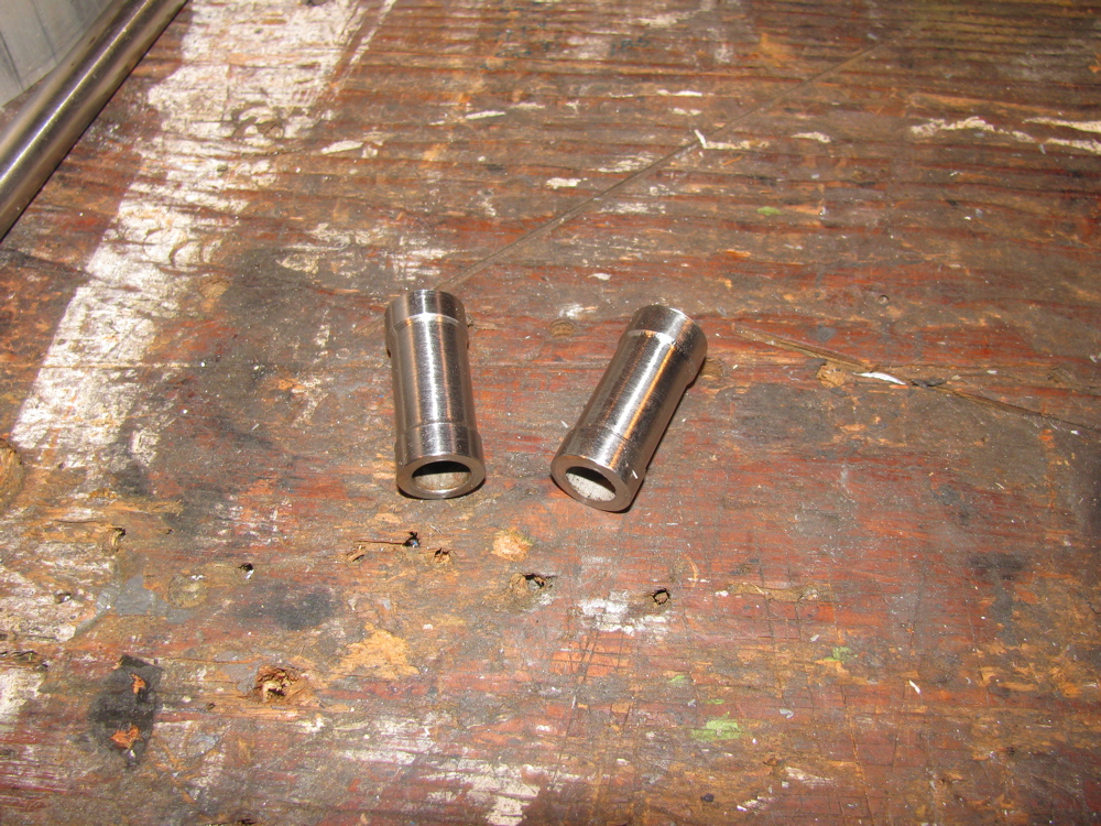
Sway bar drop link sleeve modification
Posted by albell in metalworking, syncro specific repairs on July 22, 2010
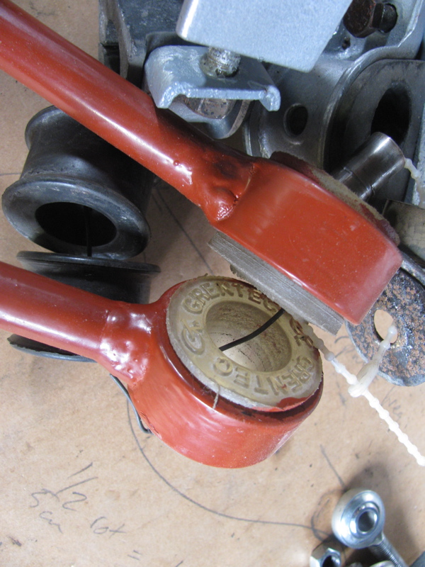
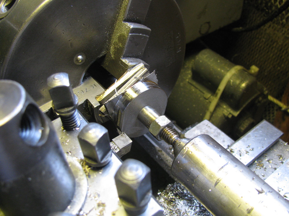
Fellow syncro owner Doug M. pointed out that I had made the drop link sleeves too tight a fit in the radius arm hole and that would limit the amount of movement needed in the rubber bushing-drop link connection. He is right that the joint there needs some degree of movement, limited and moderated by the rubber bushings. So to correct this I lathed down the centre sections of the sleeves, from 0.650″ to 0.600″. I had to make a quick and dirty mandrel to mount the short sleeves on the lathe. The length of the narrow section was judged by eye so consequently the 2 sleeves are slightly different.


Back to Cyclekart
Posted by albell in cyclekart, metalworking on July 18, 2010
Dug out the bits I have already made and re-started the project. I can’t find suitable leaf springs for front suspension yet, I’m not willing to mail order horse buggy seat springs just yet. Will keep looking and also explore using the spring/shock combo from a Motobecane moped (2 mopeds were the source of wheels for project).
Some useful links about cyclekarts:
Steve C’s blog and cyclekart build
Pretty darn good cyclekart site
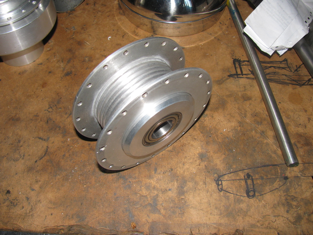
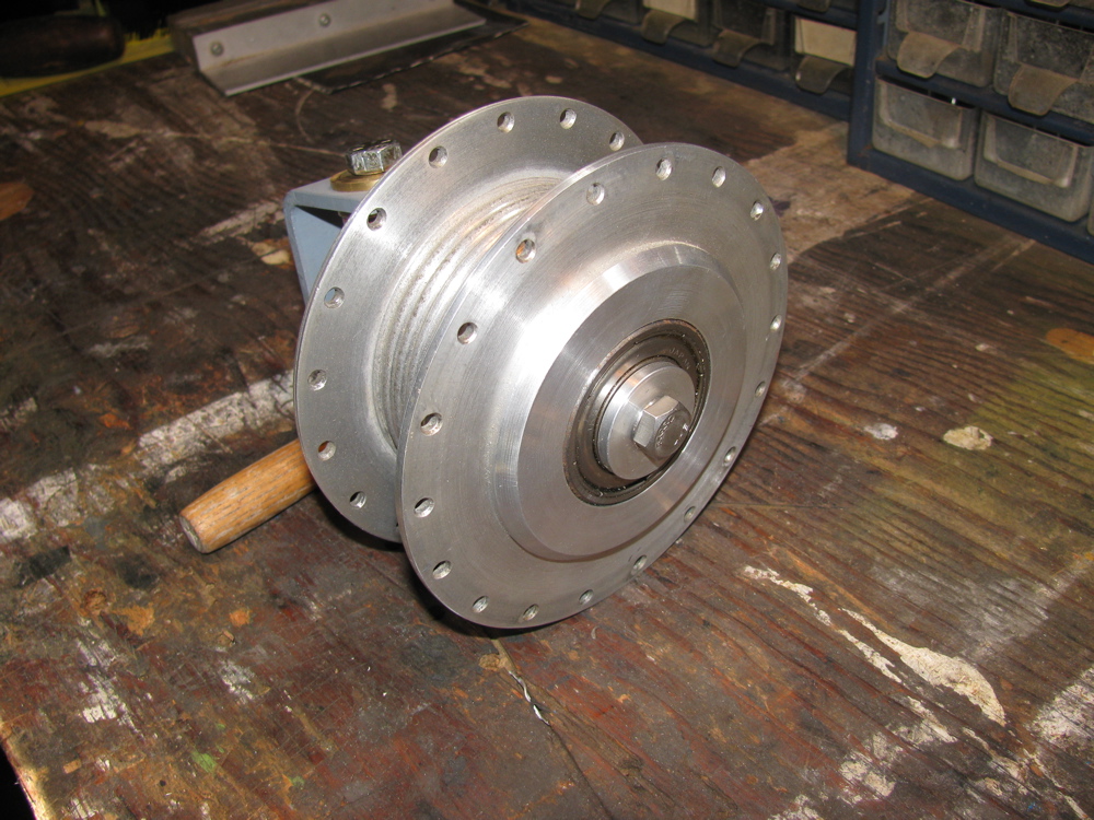
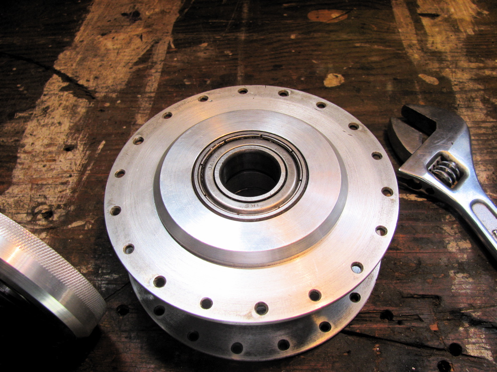
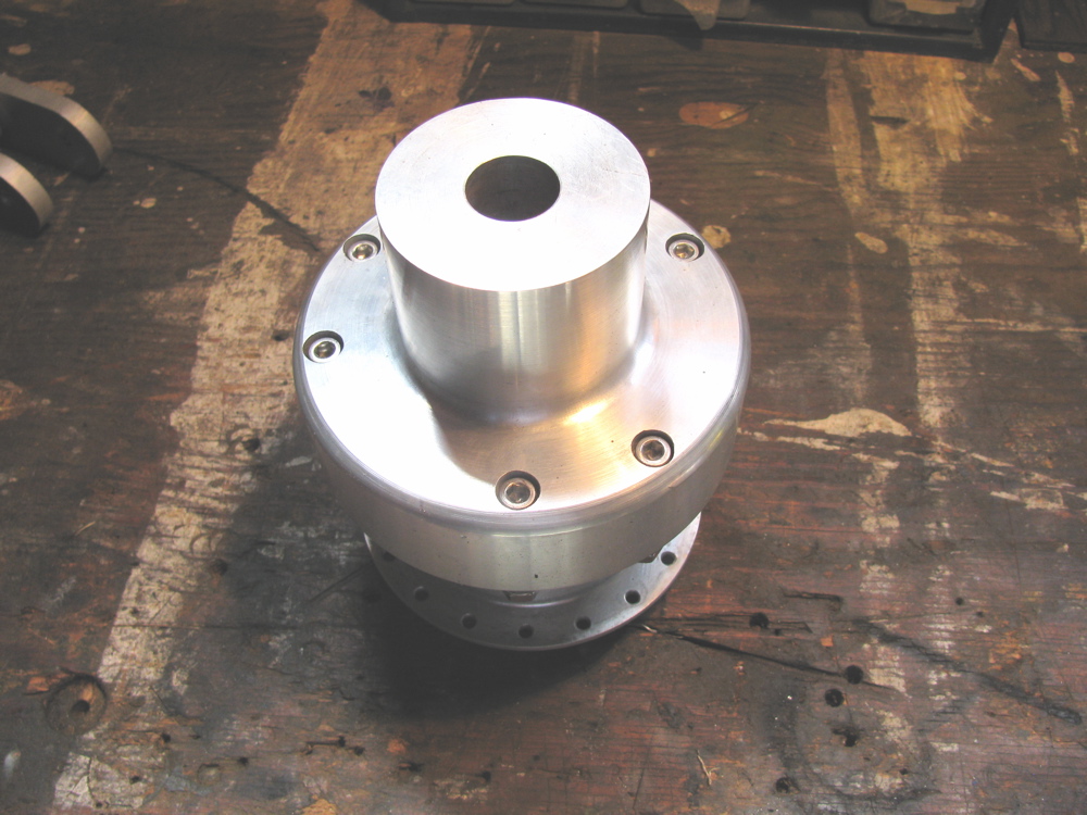
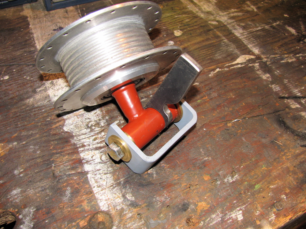
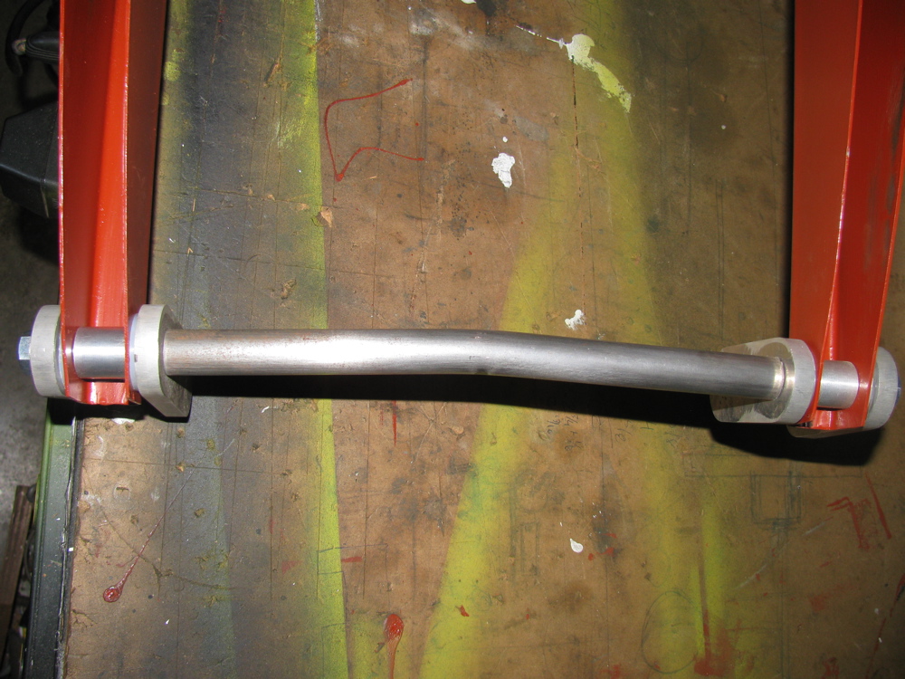
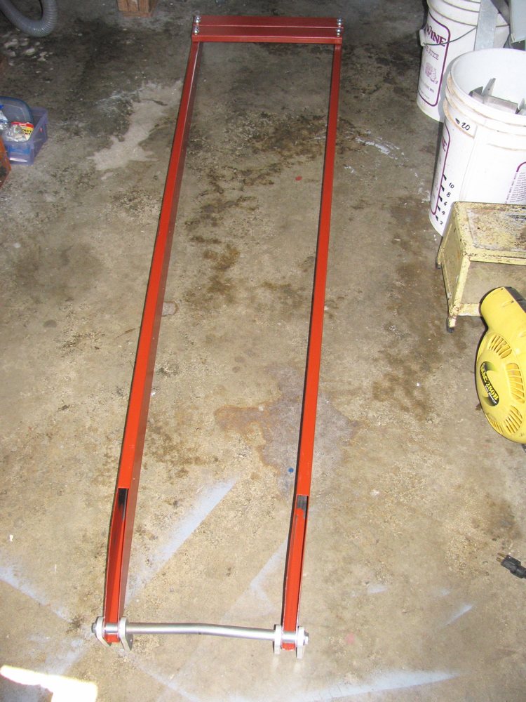
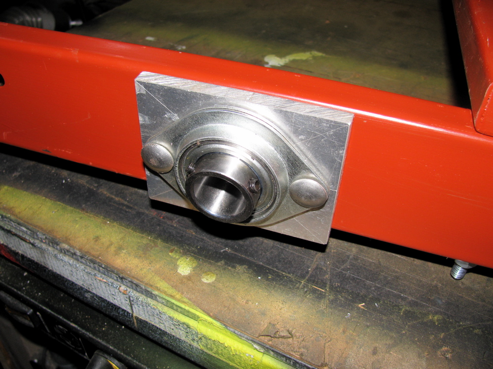
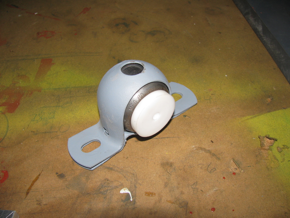
Below is gallery of the parts I have made so far for my cyclekart.
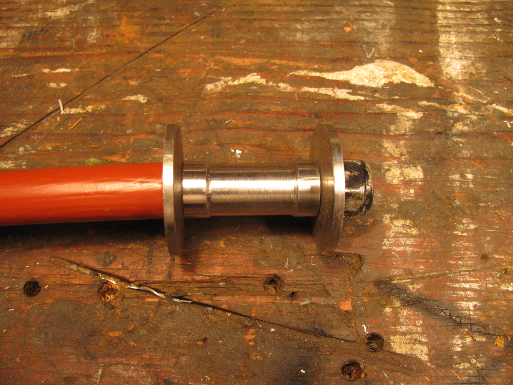
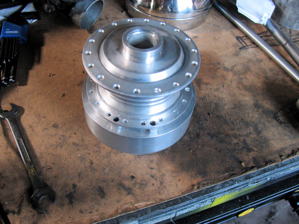
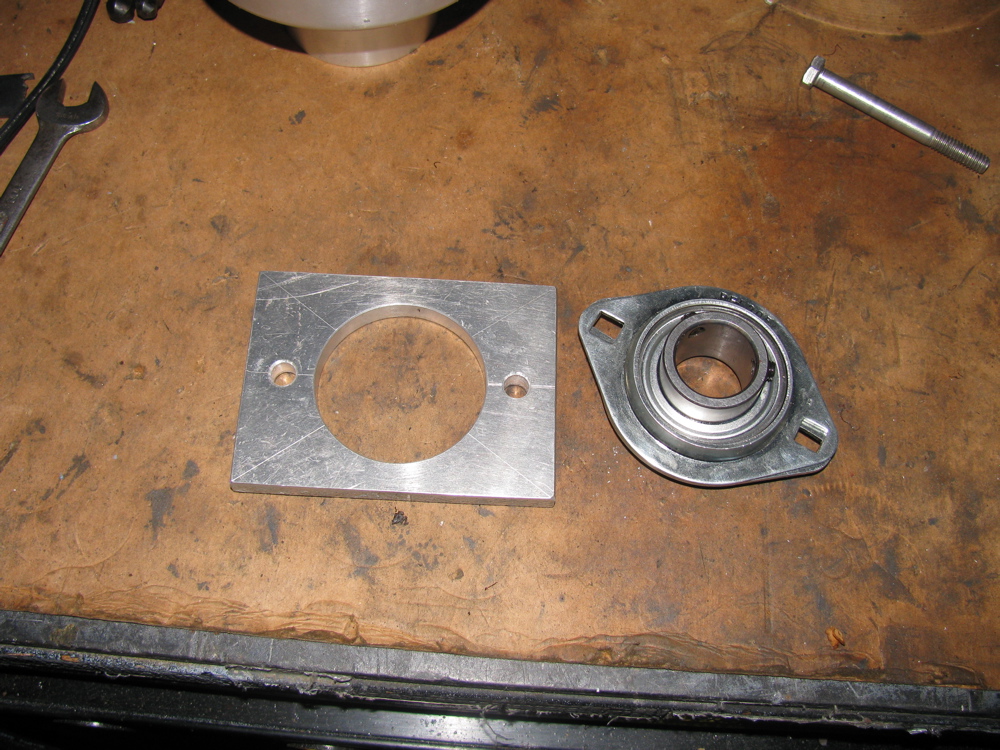
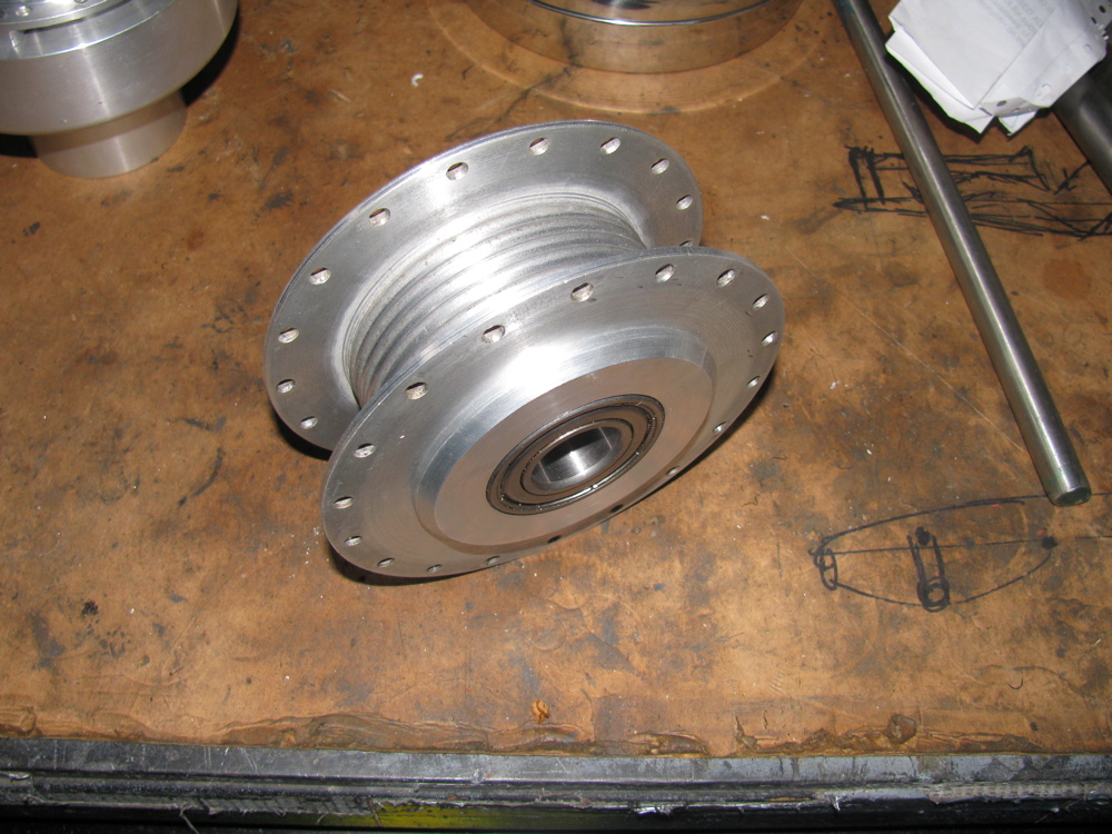
Oh a couple of notes: I have machined the moped hubs and made adapters out of aluminium, both for front and rear wheels. Rear hub adapter not keyed to axle yet, and the freewheeling rear hub adapter not shown. The metal cross bar/rod shown is an experiment, I am not sure if I will go with it in final car. Its bent to allow machined shoulders to lie flat on frame sides. But it really didn’t turn out the way I imagined. The white plastic bit in grey metal holder is potential steering rod bearing.


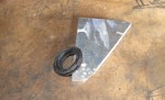
Sway bar drop link refurb.
Posted by albell in metalworking, syncro specific repairs on July 11, 2010
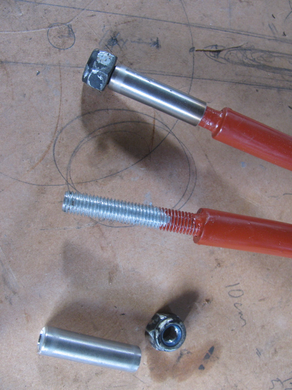
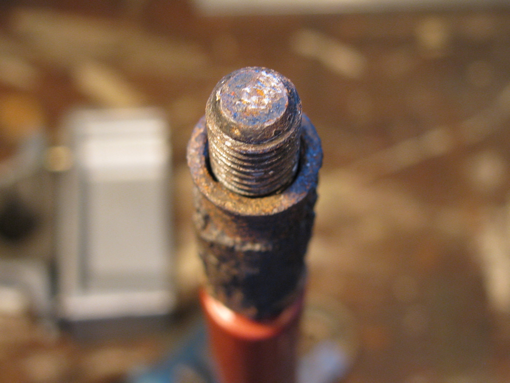
Between watching the Big Game and other things, I made some metal sleeves and convex washers for my sway bar drop links. The sway bar is off the van due to a broken link which I repaired earlier . A broken drop link seems to be a common thing, and its due in part to the steel sleeve inside the rubber bushings trapping water and rusting. This can cause the drop link itself to rust and also when the sleeve rusts out may allow the drop link to move more than it should, stressing it. I fixed the link by facing off the broken stub, then drilling into the link and tapping for a 10 X 1.5 mm bolt. The bolt was screwed in and tack welded. The bolt head was then removed and threaded portion cut to size. The picture shows the repaired link and beside an original. The stainless tubing was just an early try at finding a sleeve.
And just because I thought it a neat idea, I made bushings out of old skate board wheels.
I guess a diagram is needed showing all of the parts…
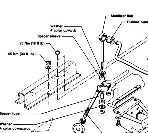
I needed to make new washers and sleeves (spacer tubes in diagram). The washers are dished and made of steel. The spacer tube is thick walled steel. I am not sure if the washers are still available, and I really wonder if the dishing is needed (allows more “wobble” in the drop link-rubber bushing connection).
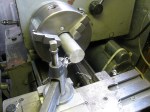
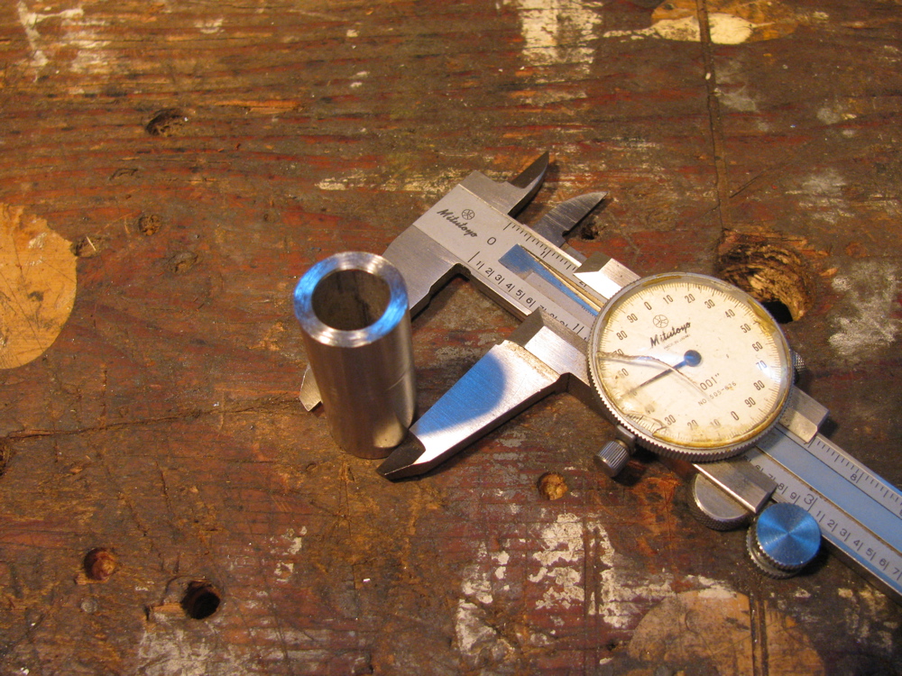
First the sleeves. Some schedule 80 stainless tubing was found at the local Metal Supermarket (I took drop link along for trial fit). I don’t know what the listed size of this stuff is, but a casual measure has it at 0.675″ OD and 0.42″ ID. The tubing was cut into 40 mm lengths (well, that’s what the rusty old stock sleeve was). I nipped out to test fitment in the hole in radius arm and found it was too large in diameter. I had to turn the sleeves down to 0.650″ diameter for an easy fit.
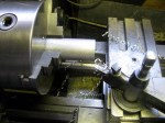
At this point I should mention that I am not a machinist, nor am I a talented amateur, so forgive any bad technique shown and the quality of the finished work. Now onto the washers. I had some stainless bar in the workshop, 1.5″ wide (not quite as wide as the stock washer diameter, you’ll see evidence of that in the pics), 0.187″ thick and I cut it up into rough bits, drilled holes in them and mounted them all on a really dodgy mandrel/spud/spigot/whatever on the lathe. Not the best technique, had to go slow and light to avoid hammering. Of course it would have been better if I had made them into hexagons at least before turning. Anyhow, I made the stack round. Then I mounted them individually on the mandrel and gave them a slight crown. Took a while but I still have my eyesight and digits.
The sturdy new washers are thicker than the old washers and this may be a problem when it comes to installing with the rubber mounts. If needed, I’ll shorten the sleeves by a couple of millimetres or so. Oh a couple of points… I was working on the “other side” with the lathe in reverse when making the washers convex. And you can see evidence in the finished washers that my stock was not quite wide enough, not big deal, just aesthetically crap.
Oh, one more thing, I ground off the little collar seen around hole in washer after I took the pics. The collar was left over from the lathe work. When the washers and sleeve are assembled on the drop link, and the nut is tightened, it all feels pretty solid and strong. I still would like the sleeve to be a snugger fit on the drop link, but probably is just fine as is.
I need to find some rubber bushings now. You can buy stock ones, but criminy, they cost $10 a pop!
Edit: see here for sleeve modification


PS. For images and prices of the “real” parts, check this page from Van Cafe
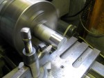
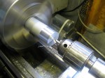
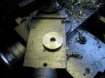
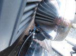
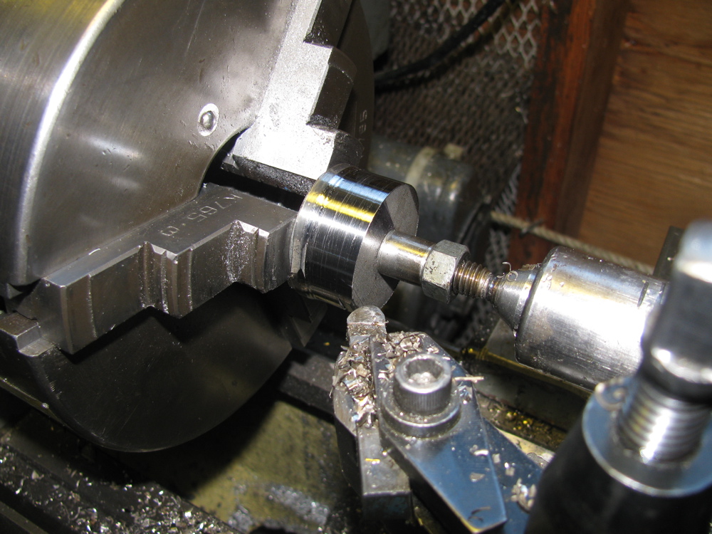
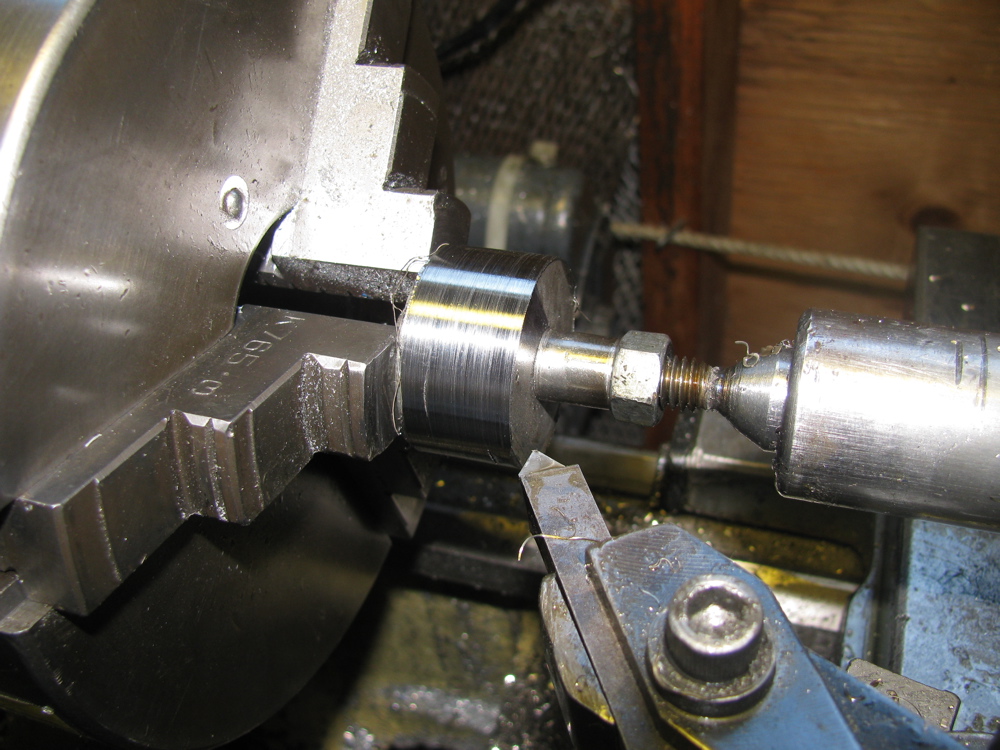
Making aluminium shavings
Posted by albell in metalworking on March 10, 2010
To make about 2/3 of a garbage bin of shavings, take a lump of 8″ aluminium round bar, and lathe away half of it over a cold afternoon in the workshop. What an inefficient way of doing things, but I ended up with a solid one piece flywheel for a non-vanagon project.
Note: I had to drill and tap two holes to bolt the stock to the faceplate, formed the “hub”, then could unbolt, flip it around and grab the hub in jawed chuck to finish other side. I feel compelled to say that I am by no means a machinist, just a home hobbyist.


Multi-prong connector tool
Posted by albell in metalworking, tools, vanagon on February 28, 2010
Another trivial lathe job…
My ’86 Vanagon fuse box has multi-prong connectors in back. Some are spade, but most are the round prong variety, very similar to “Molex” brand. The individual metal connectors insert into the plastic blocks and are held in by “barbs” on the connector shaft. You can’t pull the connectors out of the block without damaging those barbs unless you have the special tool.
I made a couple of the tools for each size of connector. I used a large nail (spike) for stock and I have to admit to not really having confidence that the idea would work, so the you have to forgive me for choice of material and final finish. I am pretty sure there are commercial versions of this tool, better made and with a nicer finish.
As it turned out, the tools work perfectly well. You just insert the tool into the block, the barbs are pressed back into the body of the connector and the wire can be pulled out from the back of the block. The pictures below show the smaller sized tool. Jeez, I didn’t notice the rust on the little vice until I took the pictures. Winters on the west coast, damp and the workshop is not well sealed….


Update: Google “Molex pin remover” to see some nice and inexpensive commercial and home made versions.
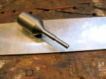
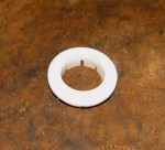
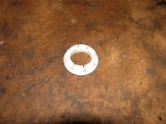
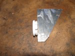
Sliding door escutcheon
Posted by albell in metalworking, vanagon mods on February 14, 2010
The handle on the sliding door of Vanagons is secured only inside at the lock mechanism. At the outside door skin, the handle shaft passes through a rubber grommet “escutcheon”. This grommet does nothing to support the handle and is there only to prevent water ingress inside the door. The problem is that the forces applied when you use the handle puts a strain on the pot metal handle shaft and can, after some years, cause the shaft to break. I have seen an aftermarket replacement for sale on Ebay (link here) and it looks pretty good, made of black Delrin. I thought I would have a go at making something similar.
I had some
high density polyethylene
UHMW polyethylene rod
I thinks its actually teflon after buying some more UHMW and comparing… I feel dumb.
in the scrap bin and I chucked it up on the lathe and had at it. If I was smarter I would have just made it as a shouldered bushing, but I went to the trouble of making a groove to fit the door skin and then cutting the inner flange to allow it to press in place and remain secured. I don’t think you need to go to all that bother. Pictures below, you can see what I mean. The white poly does look a little daft, but hey its what I had lying around. It really makes a difference on how the handle feels when you use it, no looseness, it feels secure. Oh, also is one pic of the old stock rubber grommet.

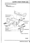
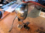
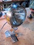
Fog/Aux. lights installed
Posted by albell in metalworking, vanagon mods on January 21, 2010
Finally finished the job. The bracket and light combo as originally designed did not allow the lights to point ahead without the backs hitting the lower grill. I put the aluminium spacers shown in previous post between the fog light and the right angle part of bracket. This pushed the light forward about 1/4″ providing enough clearance at the back.
I had planned on using the factory wiring set up (see German wiring diagram below) but have any of the pin type connectors (very much like Molex connectors) needed to plug into positions C22, B16, and B20 (multi prong connectors at back of fuse panel). But the surprising thing (well to me anyway) about the stock set up is that the additional relay added to “relay position 7” serves only to supply power to switch and not to isolate switch from the full light current. Just as it is a good thing to install relays in headlight system to reduce current load on headlight switch, I figure same approach should be taken with the aux. lights.
My version uses spade connectors and goes like this:
(this is for an ’86 syncro passenger van)
-G7 single point connector on back of fuse panel to + connector on switch *EDIT* I changed to use G3, X-relay power
-G9 single point connector on back of fuse panel to “30” on relay. G9 is fused through fuse # S20, license plate lights, I swapped in a 20 A fuse.
-connection from switch to “85” on relay.
-connection from light bulb on switch to ground.
-connection from “86” on relay to ground.
-connection from “87” on relay to fog light positive.
notes: the foglight switch is a 3 position switch and has 2 connectors on it, one for front fog light, one for rear fog light. It also has a light in it that illuminates when switch activated. The relay (40A) is mounted in one of those nifty bases that dovetails onto edge of fuse panel. G7 only has power when headlights are on *EDIT* I used the G3 spade, X-relay powered. so it gets power when ignition on. I grounded the lights via the right hand side lower radiator bracket bolt. The positive wire from lights passes through bumper sub frame via a grommeted hole, then up behind grill alongside the left hand edge of radiator then through body via a factory installed but unused grommet.
*EDIT* here is my circuit diagram as used

And here is the factory wiring.


Fog/Aux. light brackets
Posted by albell in metalworking, vanagon mods on January 18, 2010
Been mucking around trying to make some fog light brackets. I’m following the factory method, somewhat. Bending 1/4″ stainless stock (by hand, using some heat) and using some aluminium angle. Stuff I had lying around. The Cibie lights I want to use are quite deep, so the install is not going as easily as I would have wanted. The pics in the gallery show a page from the German manual, a shot of a repro bracket made in the UK, and my efforts. I didn’t make the final bend on my bracket, I wanted to use the aluminium angle to give me a bit of adjustment room fore and aft. Also, I think the final bend makes the bracket more flexible. But the result was a light too close to the lower grill. So I needed to make some spacers, and take boring pictures of the lathe. The brackets are affixed to the frame below the bumper by plastic wall anchors for trial fitting, when I am happy with the fit I’ll use stainless bolts. Oh, and yes, I painted them with rattle can bed liner stuff. Lots of stupid pics of lathe work 🙂