Archive for June, 2012
ATA – Sikorsky S61N
Posted by albell in aircraft, around the airport on June 30, 2012
Been a while since last aircraft pic, but spotted this one for first time today. Owned by VIH, but not painted in their colours.

Vanagon – another use for scrap aluminium
Posted by albell in syncro, vanagon, vanagon mods on June 25, 2012
This time a bit of aluminium grating and it couldn’t have been easier to make – I cut it into two sections. Looks like it might work out in the field using rocks or wood to raise one end. BTW, my transmission bash plate seems to have generated a lot of chatter about increased transmission temps due to reduced air flow over the transmission. As with most internet chatter, no data given to support opinions but I hope to be able to do some temp measurements using IR gun (yes Simon, I’m going to ask to borrow it).


Vanagon – syncro bash plate project finished
Posted by albell in syncro, syncro specific repairs, vanagon, vanagon mods on June 24, 2012
Well the transmission protection part anyway. I decided to leave the plate mostly rectangular, but I did have to curve the front corners for no other reason than I thought it looked better. I also drilled some drain holes at the rear of the plate. Instead of using the drill press, I used the wrist buster, aka Van Dorn drill.

I made rather ugly holes with it, but I rationalized that (and other goofs) with the “it’s only a skid plate” mantra. I cut out slots for the stock skid bars and bent up the leading edges slightly. You can’t bend up that middle section too much or it will hit the nose cone of the transmission. I also gave the bottom of the plate some DA love.

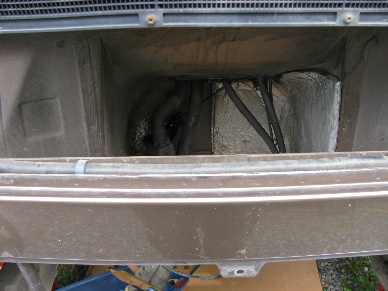
I found it a real pain in the arse installing the stock skid bars by myself, but installed they were. See how exposed the transmission appears? Like having your goolies hanging out.

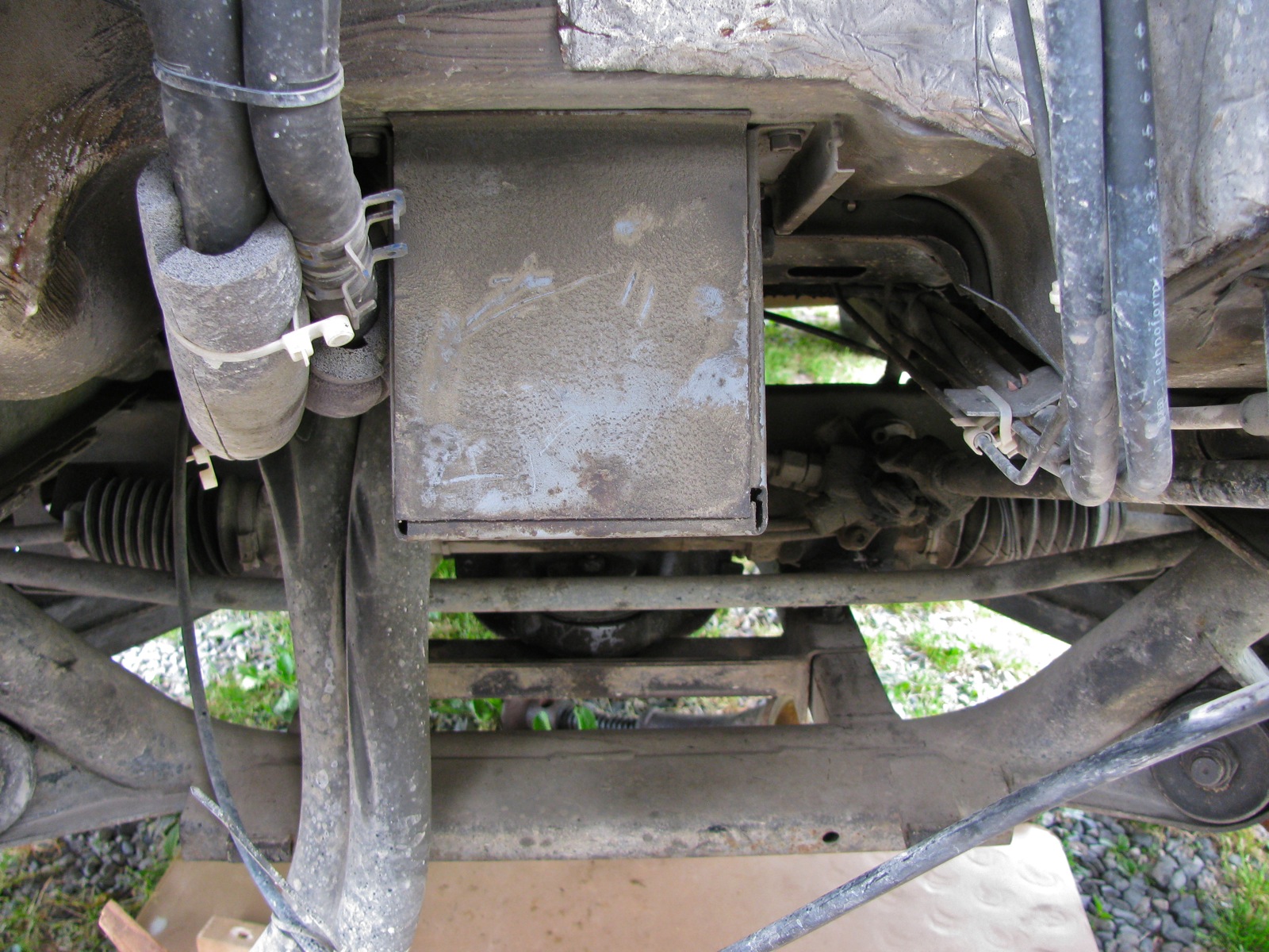
And same view with the plate installed.

Front view.

I think the extra width will help protect the inner cv joints and the fuel pump. Note to Simon, will also protect the speed sensor and that big electrical plug on driver’s side. But not sure about fitment around exhaust on your 2.5 Subie.


Next job will be to add some 1/4″ aluminium plate between the propshaft protection bars, and perhaps to extend that protection out sideways and attach to frame rails. That will help protect shift linkage and coolant hoses.
Damn. just occurred to me, forgot to paint the stock skid rails where I ground off the paint for welding the tabs on. I guess the project is not quite finished.
Vanagon – syncro bash plates project
Posted by albell in syncro, syncro specific repairs, vanagon, vanagon mods on June 22, 2012
I left the entire syncro drivetrain protection bars off my van after the propshaft business with a mind to installing some bash plates. The transmission is left pretty well fully exposed in the stock set up, and today I started doing a bash plate in that region. I had some scrap yard sourced 5/16″ aluminum plate to use.
Here are the stock skid bars/rails, transmission end. See the added tabs?

I had my first go at TIG welding…I still have a long way to go.

A real welder (good friend Dave) did the stainless to plain steel weld (609 rod).


Pretty heavy gauge aluminum, but it was cheap.

I match drilled and countersunk holes in the plate to match the nuts on the rails. The tabs with nuts were not located with any special measurement in mind.


Other side view. I’ll offer the assembly up to the van and see how much of the plate I’ll cut away. Rough sketches on plate sort indicates my thinking, “wings” towards the rear to provide a little protection to the inboard cv joints.

Project finished, blog post here.
Vanagon – radiator replacement (mine)
Posted by albell in syncro, syncro specific repairs, vanagon on June 21, 2012
Not really much to add to the previous rad replacement expect that it is my van (’86 syncro) and I thought I’d make it a post just for my documentation/memory aid purposes. I suspected my rad needed replacement for no other reasons than I think it is the original rad and that I noticed the rad fan coming on more often when idling after a hwy drive. The replacement is a Behr unit, made in South Africa. The old rad still had the a/c condensor rad attached in front, probably not helping heat escapement. The new rad did feel lighter than the old one, whether this is due to deposits in old rad or construction details I can’t say. No real details to note except that it is a pretty easy job. I clamped off the coolant lines so a total coolant replacement was not done, I glued on the little rubber washers on the spikes on top and bottom of the rad (so that they didn’t fall off during installation, and I sprayed Fluid Film on exposed fasteners in the general area. After install and bleeding, I have only idled van long enough (took 20 minutes) to get first stage of fan to come on, no road test yet.


Workshop find – Pug with a Pipe
Another discovery made whilst cleaning up my stepfather’s workshop, a pug with a pipe! Both my mother and my stepfather did not want it, so I snagged it before they changed their minds. Some folk have no taste eh?
It’s hard to get a good shot of it, size and glass working against me, but here is one attempt.

Interesting stuff on the back, label indicating it was purchased in England?

But the paper glued down to seal backing to frame appears to be from an American newspaper, fashion and automotive sections!

My prime evidence of it being at least a North American newspaper.


Vanagon – GoWesty Wasserstopper rain fly hook issue resolved
Posted by albell in vanagon, vanagon mods on June 8, 2012
I received replacement hooks from GoWesty for the Wasserstopper rain fly. I had complained that original hooks held on to the gutter poorly. Good customer service!
The replacements do hook on to the rain gutter much more securely, but I haven’t had the chance to fully test with them attached to fly.
My best pic of original hooks, they end up hanging on by fingernails.

Replacement hook.


Vanagon – that transmission noise fixed?
Posted by albell in syncro, syncro specific repairs, vanagon on June 7, 2012
I’m just back from test drive after installing my re-bushed propshaft and I can report that the noise I was hearing, and that I had thought was transmission noise, has gone! I’m chuffed!
But to ward off the Evil Eye, I’ll not claim victory.

Vanagon – making new syncro propshaft internal bushings – Part 2
Posted by albell in syncro, syncro specific repairs, vanagon on June 6, 2012
I decided to make a split bushing for the internal location. I first turned down some Delrin to final inner diameter (23 mm to match the turned down yoke shaft), then mounted it on a mandrel to turn down OD to 28 mm (was OD of upper bushing and I guessed that the inner one was the same).


I kept the bushing on the mandrel and clamped it in my wee milling head. I also used a small C-clamp on the bushing to stop it from popping off during slot cutting. I used a 1/8″ end mill to cut the slot, made the slot 6.8 mm wide (chord length) which I estimated to be slightly more than needed.

Finished split bushing.

And as I tried to install it, I realized I had no way of holding it compressed to get into the narrow bore, no grip after it goes into outer bushing area. Oh, btw, this is how the bushing should appear when it is finally in place at the bottom of the housing.

I had an idea, some stainless shim stock to act like a funnel.

That worked and I was able to tap the bushing home. You can make it out, down at the bottom.

The yoke shaft would not fit in, I had to chamfer the end of the shaft a little more, and polish the end. But I finally was able to tap the shaft in and it is nice and snug. Quite snug actually, it takes about 20 Nm to rotate the yoke, but no radial movement at all. Oh and another thing, I removed that flange on the upper bushing, didn’t make any sense. I’m feeling quite chuffed in managing to get some sort of bushing replacement made. I hope they will wear well.

Vanagon – making new syncro propshaft internal bushings – Part one
Posted by albell in syncro specific repairs, vanagon, vanagon mods on June 6, 2012
I have my propshaft off while I try and track down my transmission noise (see previous post). Some helpful syncro owners over on the IG16 forum suggested that I look at my propshaft as the source of the noise. Well why not eh?
This is a story of mistakes and ignorance. When I compared my two propshafts in this post, I mistakenly concluded that one shaft had thinner walled bushings than the other. Well it did look that way and both assemblies felt equally tight – ie acceptable fit of shaft into bushings. But I think I must have been wrong for when I examined the “thin walled bushing” propshaft (the one I just removed from van), I could detect play in the bushings. The rubber giubo and the internal O-ring have been removed and dial indicator set up to measure movement as I lifted U-joint yoke up (trying not to rotate joint as I did it).
Here is diagram of that end of the propshaft just to refresh memories.

And my measurement set-up.

And short movie showing movement.
I admit to this being not an extremely accurate way of measuring the radial play, was hard to just move the yoke up and down and not rotate it. But I could feel the play and it was more than I think it should be.
So it comes down to replacing the bushings. The outer one would be relatively easy, but the inner one is a different story. And I think the inner one is important to be snug as it is at the end of the shaft and would limit shaft movement more than the outer bushing. That was a convoluted sentence, I hope you get the idea.
On the Yahoo Vanagon Syncro mailing list, the bushings have been discussed a few times. One list member wrote (a year ago?) that the inner bearing could not be replaced as it sits in a recess in the tube and was probably installed before that end was welded onto the propshaft. The drawing at top of this post does not really show the recess (drawing too small), and I had forgotten all about it.
Foolhardy is a useful adverb to use whenever I get it into my head to fix something. I kid myself that I know what I am doing, ha!
I pondered how to remove the inner bushing and came up with chiseling it out. I have this neat little 1/4″ chisel that looked like it would work.


And off I went, chiseling a groove down the inner bushing. It took a couple of groove before I could break out the bushing. I found it difficult to get a good pic of what was going on deep in there, but in this pic you can see a section of the bushing folded inwards. Sharp eyed readers will be able to see that there is a lip in the tube which locates the bushing. Bushing was pressed in from other side, then that end cap inserted (portion of bushing is obscuring the hole in the center of that end cap), and then assembly welded to propshaft. Even sharper eyed readers will notice another, smaller lip about halfway between inner and outer bushings. I overlooked this, I have no excuses why and it bit me on the ass later on.

Bits and pieces of the bushing. After I knocked the fragments out I could see the aforementioned lip. I didn’t feel very happy at that point.

I really had no choice but to go on and cut out the outer bushing. This pic shows how well the chisel cuts the bushing and the underlying steel – doh!

Note the fretting or corrosion on the surface of the bushing. Here is a close up of a fragment, looks a bit like sintered bronze, like an “Oilite” plain bearing.

So alright then, what to do about the inner bushing problem? I wasn’t about to cut the end off the propshaft. I settled on the idea of turning down the diameter of the end of shaft a tad, to about 23 mm from 25 mm (diameter at end where shaft inserts into bushing) and making that reduced diameter area about twice as long as the original bearing surface. I reasoned that a Delrin bushing could be made to fit into tube, be supported by the tube and extending on unsupported over the original bushing spot. Jeez, I need a diagram to explain.
Here is a cartoon cross-section of the end of propshaft that houses the bushings.

And with shaft in place.

Modified shaft.

And assembled with new bushings.

The drawings are not to scale and are meant just as sketches to get my idea across. Important thing to note is the new internal bushing will come further up the shaft, and be unsupported in old bushing area.
Off to the lathe!
Mounted yoke shaft between centers, was lucky and set up resulted in less than 0.001″ run out at end (inner bushing area).

Then turned the end down to 23.00 mm. I found it hard to get a nice surface finish even with very light cuts. I was using a round nosed HSS tool bit (has given me nice finish on other jobs), but this time I had problems. So, a less than perfect finish.

Chamfered the end and gave it a quick polish. I think it will be good enough.

Next step is to make the Delrin bushings. Whoa, slow down sonny! Have another look inside the propshaft, it is not quite the same as you describe in your sketches. Go on, look at that picture you took of the bore. What? No! Really? , let me… well gosh darn it.

I missed this before I thoroughly cleaned out the bore – the bore is machined out slightly for a little way, above the machined out area for the internal bushing. Illustrated, but exaggerated and not to scale, the slightly bored out region is not as large a diameter as illustrated, but it still screws things up for me.

So my original plan of a longer internal bushing will not work, see?

I decided to make the outer bushing, classic avoidance behaviour. I actually made 2 outer bushings, first one really as a practice piece, second one with a lip. I also went ahead and, again for practice, made the now discarded inner bushing concept.
Delrin rod (1.5″ diameter but turned down a tad before this shot) and boring out to fit yoke shaft. Gotta love that chipped cutter I am using, funny thing is that it does a nice job on this plastic.

Bored out to size, 25.00 mm.

I made a quick and dirty mandrel to mount bushing so that the outside diameter could be turned to size.

Then to get the bushing off the mandrel, I bored out the end of the mandrel.

To make the “practice” inner bushing, I first bored out Delrin to size, parted off, then mounted oversized bushing to yoke shaft to machine down to size. Note the outer bearing installed first. Makes you wonder if I hadn’t realized the issue with the propshaft bore yet, doesn’t it?


As I mentioned before, I went on to make another outer bushing and gave up for the evening.

Back to the problem of, in essence, installing a bushing from the wrong end. How about making the bushing the squeezing it to deform enough to be pushed in the bore and end up in position, then use a tool to form it back into shape, against wall of bore? Nope, daft. Well how about taking propshaft to machinist to bore out? Well, that might be the fall back solution. Ok, how about a split bushing? Would that allow the bushing OD to be reduced enough to be pushed in and then expand in correct place? Mmm, maybe, worth a try?
Something like the Iglide Clip2 plastic bushing (but without the end flange)?

The nominal diameter of the bore is 26 mm, and where the internal bushing is located, 28 mm. Circumference of bushing should be (pi X 28) 87.96 mm, and to fit in through 26 mm bore, 81.68 mm. So slot in bushing needs to be at least (87.96 – 81.68) 6.28 mm. Seems like a large slot to be cut. One thing in my favour is that the yoke shaft does not fully rotate in the bushing, just a few degrees allowed by the flex in the Giubo. A diagonal slot as shown in the Iglide bushing above would provide better support of the shaft so it is worth a try cutting the slot that way.
This post is getting rather long and rambling and I have other work to do, I’ll try making the split bushing later and report back in another blog entry. Feel free to give me a hard time in the comments section, I deserve it 🙂
Vanagon – transmission noise hunt
Posted by albell in syncro, syncro specific repairs on June 1, 2012
For the last couple of months I have been noticing a slight whine/howl when driving no load/coasting, in 3rd/4th or neutral, clutch in or out. Only in a narrow speed band, 50 – 60 kph. I’ve discounted rear wheel bearings and I resolved myself to having trans. taken apart and examined. So I started the pull process, first with skid bars and propshaft. After they were out I decided to drive van and surprisingly the noise was gone. So what does this mean? Maybe front diff is making the noise or is the removal of propshaft affecting whatever is noisy in transmission?
I pulled the front diff and took the case apart, 3 sections. Front cover and rear section. Mid section has R&P and I set that up to measure lash on the R&P.
Rear section removed (note spacer not on top of VC, I took it off before pic, sorry)

Front cover removed (cover was cleaned before shot).

I clamped the input shaft so it wouldn’t move.

And then set up dial indicator on outer part of ring gear tooth.

Close up.

I wiggled ring gear back and forth and measured lash. Was in spec (0.004 – 0.010″).

And teeth looked ok. Mind you Daryl at AA Transaxle says ring teeth don’t usually show wear, its the pinion teeth that do. Hard to really see them when in case.

During removal I had to cut the vent line as I forgot to remove banjo bolt securing it to case (did same thing last time I removed diff, doh). So I made up a nipple and added a section of vinyl tubing.

So where does that leave me? Daryl is suggesting it is the pinion bearing in the transmission and I can still drive it for a while. I’m not clear on how the propshaft affects that bearing but I don’t feel quite as pressured to tear into, or have a skilled person tear into the transmission.
Addendum: Dirk over on the IG16 forum, wondered if the ring gears did actually show unusual wear. He pointed to lines parallel to the teeth. I don’t think that these marks are anything to worry about.


