Archive for February, 2014
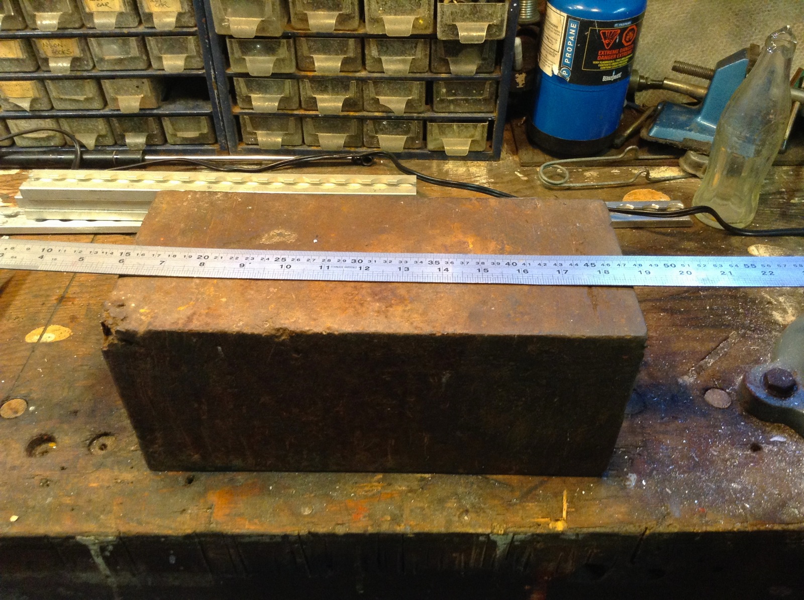
Hunk of iron
Posted by albell in metal working on February 23, 2014
Well I say iron, but it could be steel. Measures 5 1/2″ X 5 1/2″ X 12 3/4″ ( 140 mm X 140 mm X 343 mm).
If it is pure iron then it weighs around ( at 7.87 g/cc) 52.9 kg.
I don’t-know why this hunk o’metal pleases me, but it does. Probably says something about how easily amused I am.
Vanagon – swing away tire carrier – more on the latch
Posted by albell in vanagon, vanagon mods on February 20, 2014
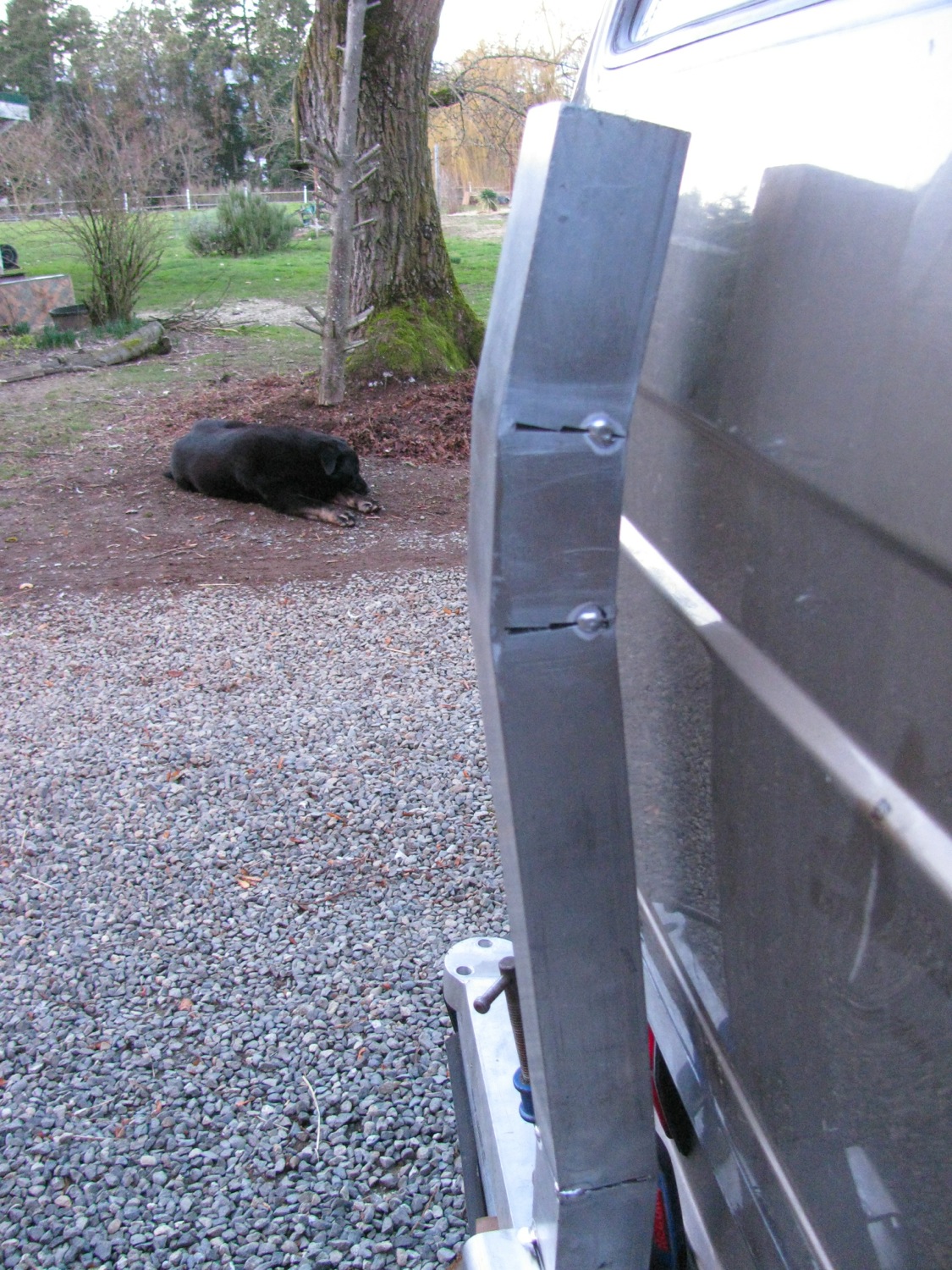
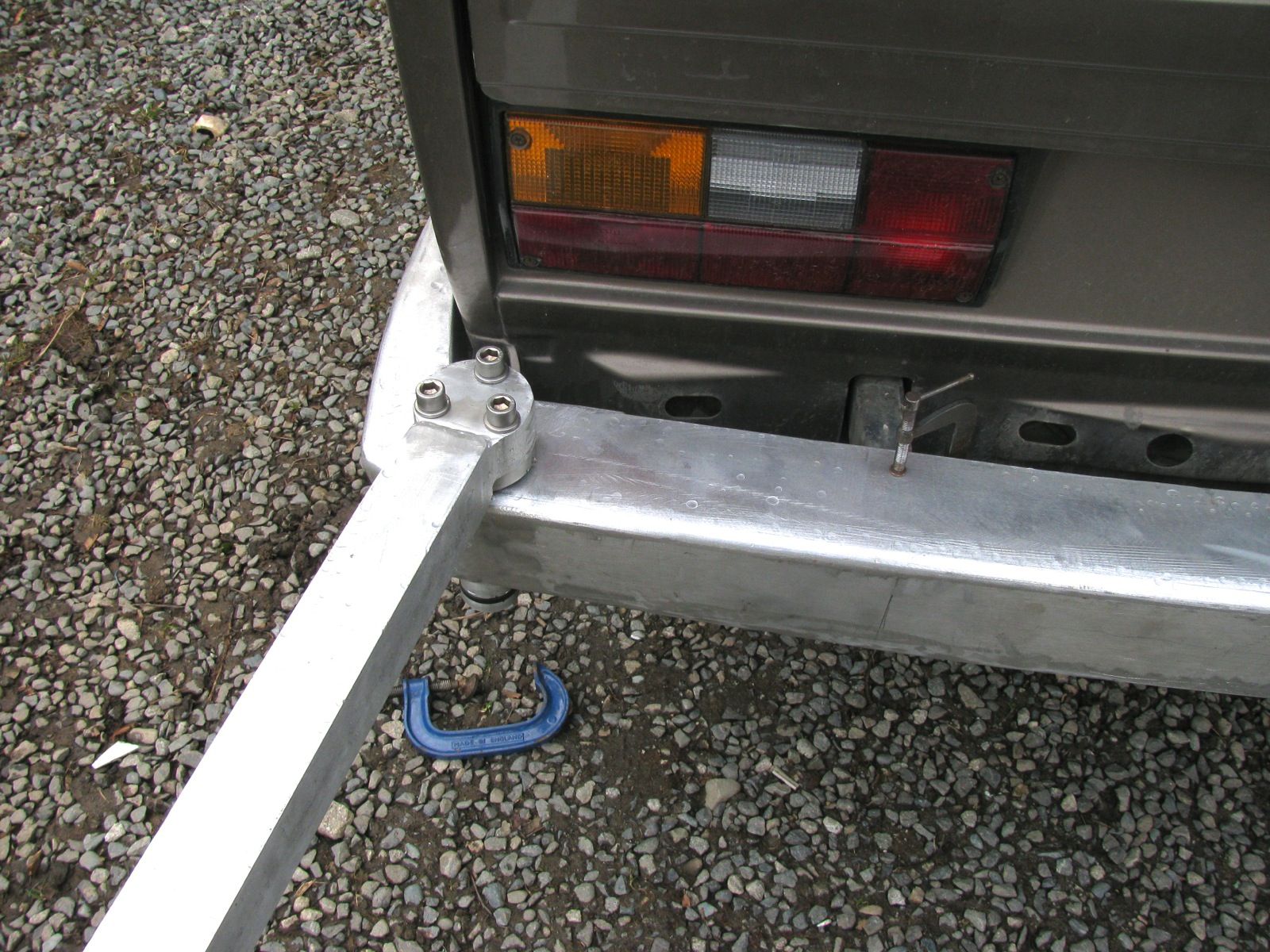
Ok, I know this conical latch idea of mine is flakey but bear with me. I got some things tacked up today to see what was what. First is the upright that will hold the spare tire. In my last post I said how I had to make an adjustment to get the upright close, but not too close, to the back of the van. My solution was to cut and bend the upright to mirror the profile of the rear of the van. Here are some pics with the upright (not fully welded out yet) roughly in place. My swing away arm is just clamped to the stock bumper.
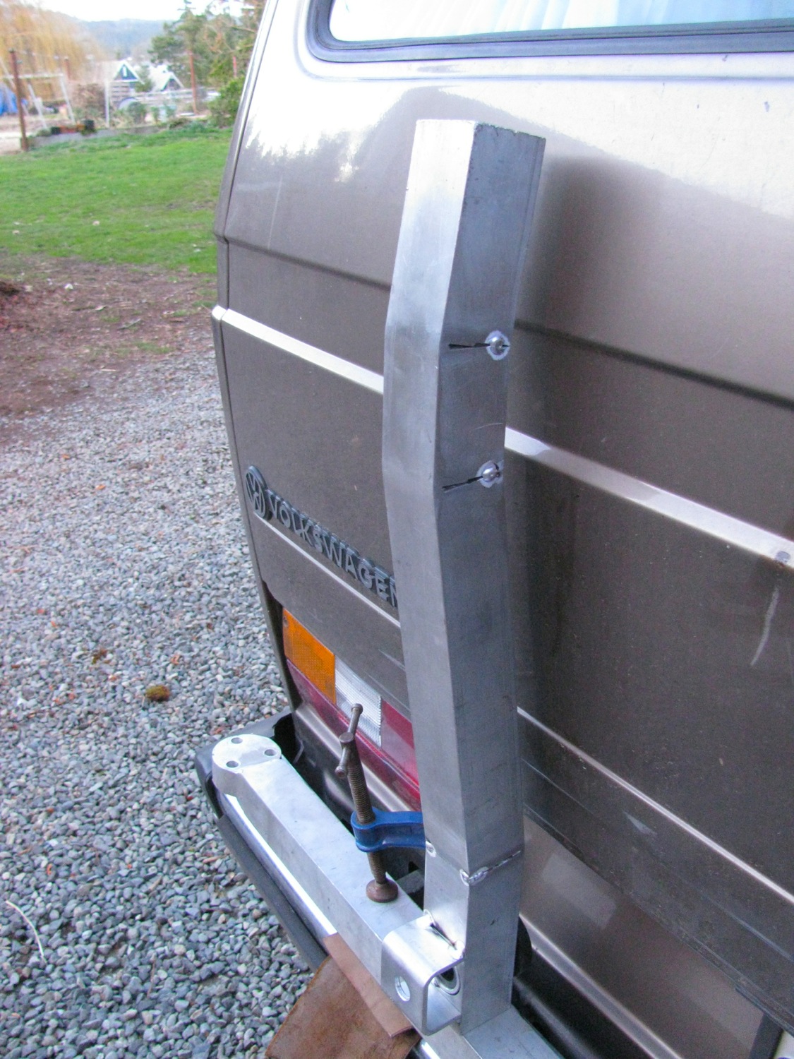
I think this might work.
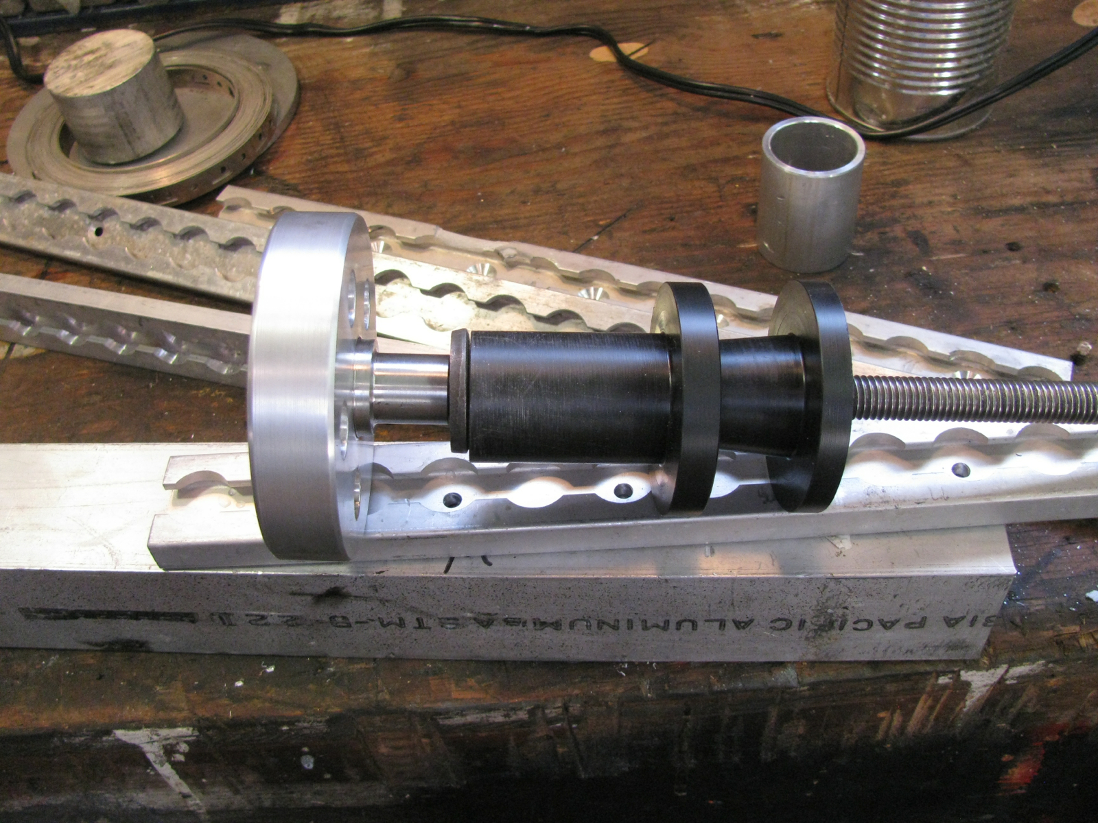
Ok, on to the latch. I tacked welded a bit of U channel onto the upright and I also bored a hole for and tacked in the short section on alluvium tube that you saw in the previous post and that houses the female Delrin part of this cockamamy set up. Here is the latch assembly more or less assembled. But some notes of explanation needed. Of course the threaded rod has not been cut down to size yet, and that metal but you see right against the left most flange represents the back stop I have yet to weld to the bumper. the two flanges meeting (and I think I might slim them down a tad) are the male and female parts in tight congress.. on the right hand side of the box section upright you can just see a trimmed down nut on the threaded rod, the thread rod, then the hand wheel. See the collar in place inside the “cage”? I need to make a set screw for it. The collar does two things, keeps the hand wheel from falling out of the cage when it is unscrewed from the rod, and when the hand wheel is turned to unscrew from the rod the collar pressed against the cage and pushes the upright away from the back stop.
I really am not doing a good job of explaining this. You’ll have to wait for a video or something.

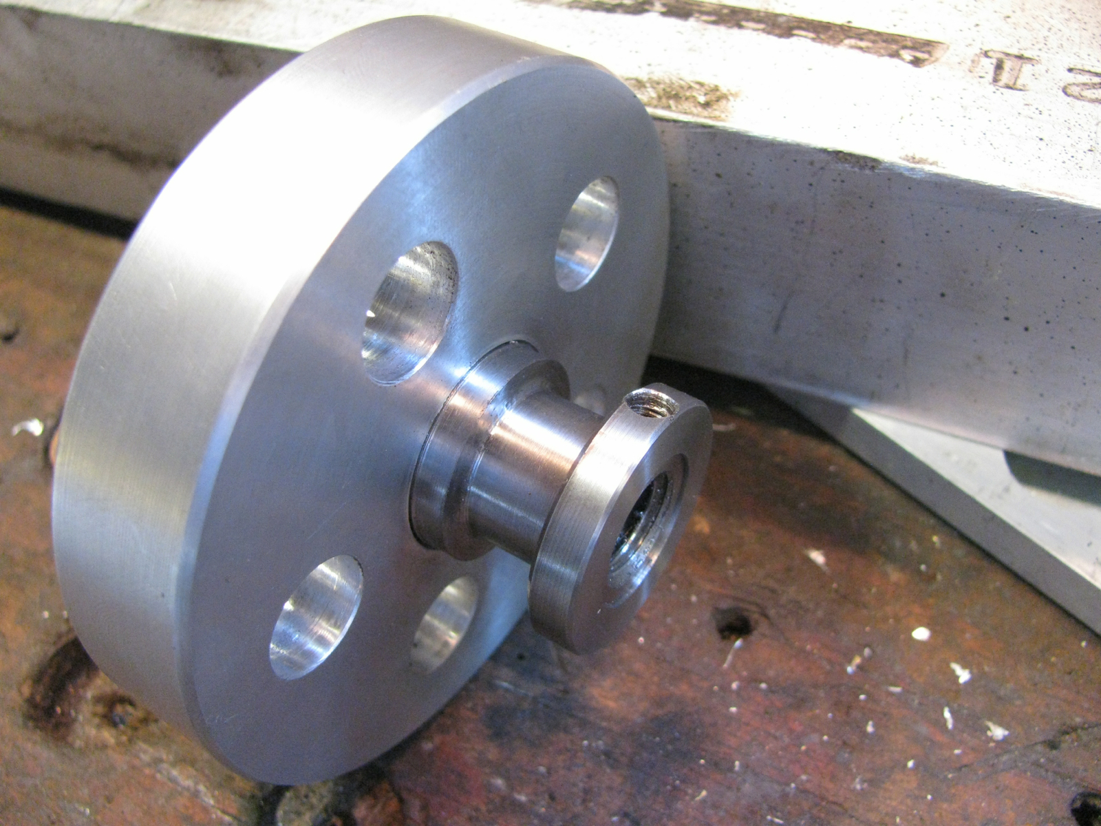
Face on view. Aren’t I a clever fellow making 5 holes in the hand wheel reflecting the five holes in the vanagon wheel? It’s this attention to useless details that distinguishes my crazy ideas from other crazy ideas. 🙂
(Here’s something educational. Click on the pic to bring it up in a new tab, then zoom in on the tack weld on the left side of the fully visible seam. You can just make out a hairline crack on the tack. This happens because the heat sink of the thick walled box section tubing draws heat away very quickly from the cooling puddle of the tack weld. To reduce the chance of this happening I should have warmed up the tubing, it was pretty well dead cold. )

Male and female separated. Time for a smoke.

I think I can weld out everything now, and trim down a few of the moving parts.
Update: 21/02/2014.
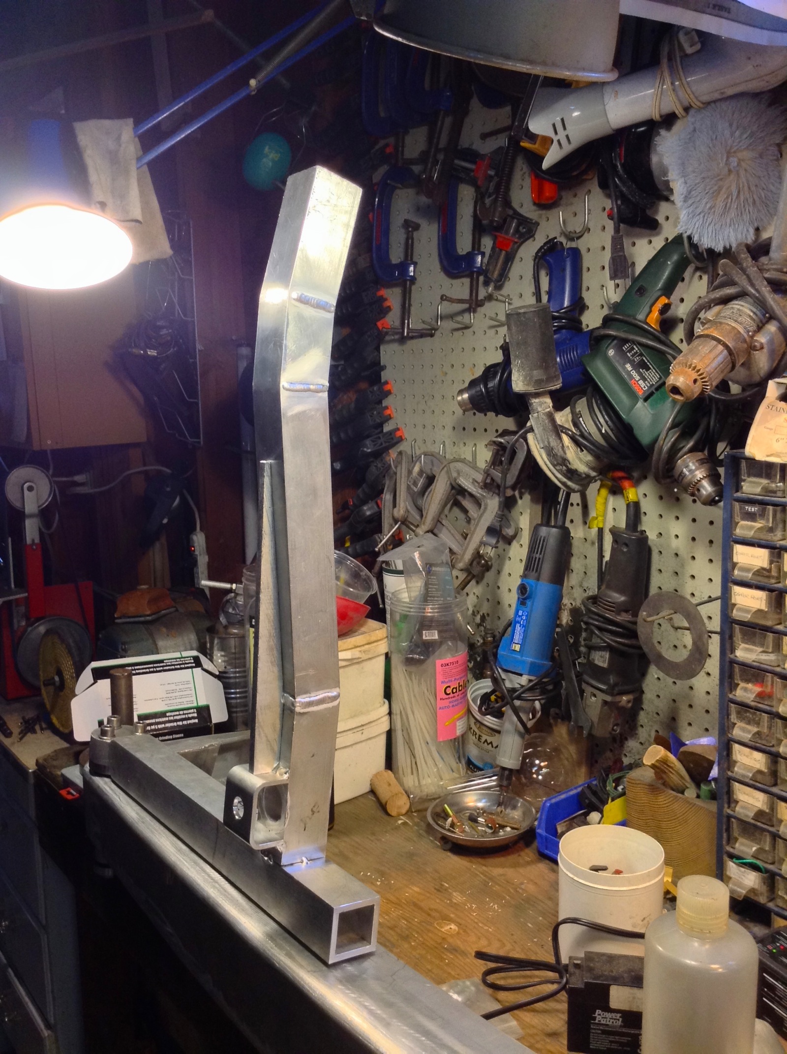
Dirk over on the IG16 syncro forum expressed some concern that the upright being made of aluminum would waggle back and forth like one of my dog’s tails. Any time a German engineer gives advice it behoves one to listen 🙂 . So today I welded up (not very well, i was rushing) the upright and tacked it to the swing arm, and I cut out a reinforcing piece to weld in (3/8″ thick 6061 stock). I am almost positive now that things will be wedding night stiff when finished.
Vanagon – swing away tire carrier latch – a start
Posted by albell in vanagon, vanagon mods on February 19, 2014
I’ve been amusing myself (!) by attempting to make a latch for the swing away tire carrier that’s going on my aluminum bumper. I have this almost unreasonable desire to make sure the horizontal arm of the carrier is fixed hard against a back stop on the bumper. I know other designs use an over the centre draw latch mechanism, and I am sure they work well. But I got in my head that I wanted to try another approach.
The back stop mentioned will be a sturdy bit of aluminum plate welded vertically to the forward top edge of the bumper. Something like a 4″ X 6″ bit of 3/8″ plate. It will be positioned at a point on the bumper were the end of the swing arm end up when the arm is “closed”. Now imagine a truncated cone projecting horizontally back from that plate that fits into it’s female mate that is in the swing arm. The cone arrangement will, I think, locate and secure the arm to the back stop.
Instead of a draw latch I decided to have a captured screw handle on the swing arm. This screw handle will engage a threaded rod projecting out from the male cone.
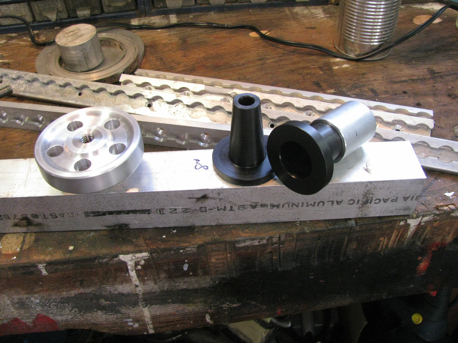
Yeah, it doesn’t seem very clear and I don’t have a sketch of my idea. But here are the parts I have made so far.
From left to right: hand wheel/screw handle, male cone (will be attached to back stop), female cone partially inserted into bit of tubing that will be welded into the swing arm.
The cone couple. 10 degree included angle, made from Delrin. It is a tight fit into the aluminum tube that will house the female cone. A bit of glue and a couple of countersunk screws on the flange will hold the Delrin in the aluminum.
The hand wheel (going to call it that from now on) is made from scrap aluminum with a centre section of stainless steel pressed in. I mean really pressed in, a shrink fit. I heated the aluminum and drove the stainless into, the somewhat enlarged by heat, hole. Then I fancied it up with a turned recess and some holes. The stainless centre is threaded for 1/2″ NC.
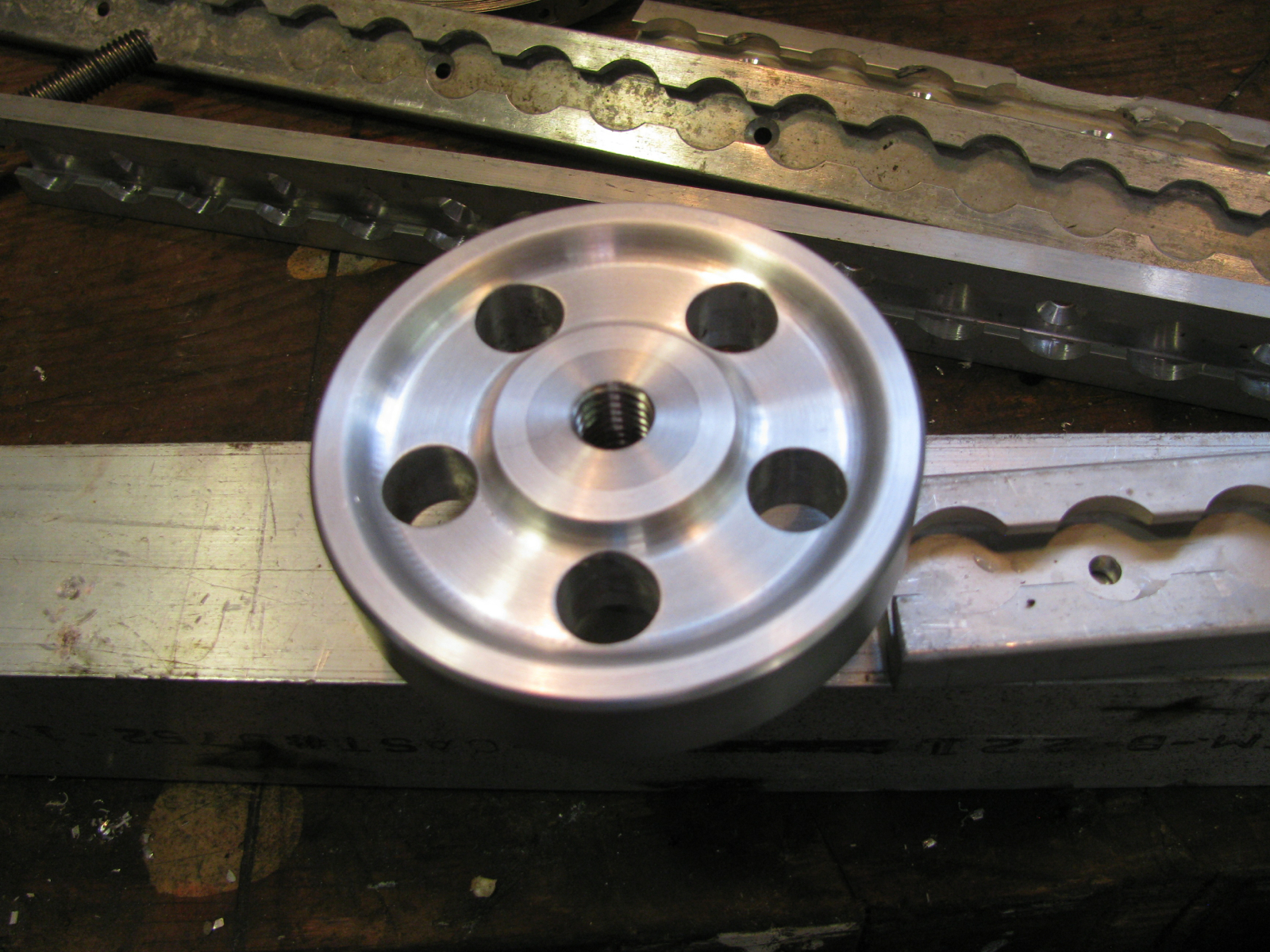
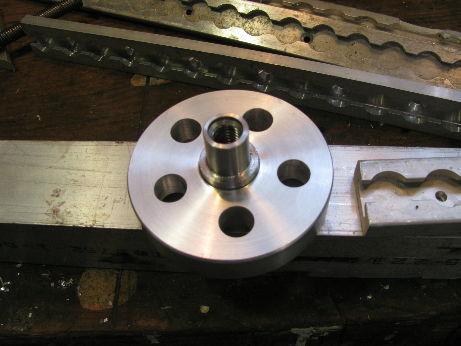
The other side. The narrow section will be inside the “cage” that I have yet to make that will hold the hand wheel to the swing arm.
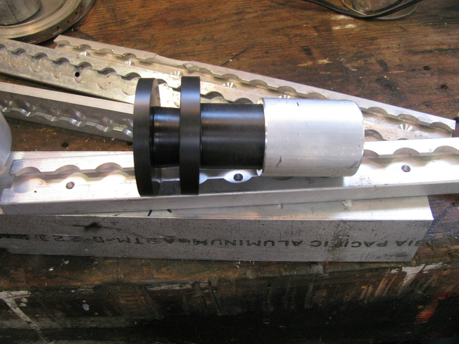
Arranged in order.
I had to make a collar to put on the narrow portion of the hand wheel to stop it falling out of the cage when unscrewed from the threaded rod. Of course I broke the damned tap when i was threading a set screw hole.
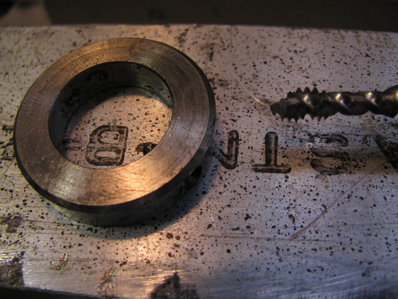
Grr.
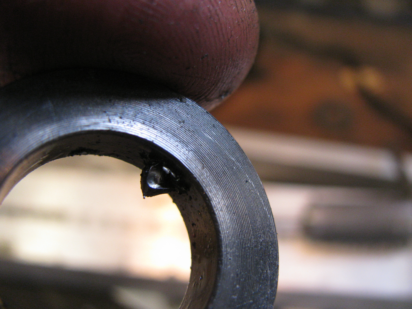
I didn’t want to make another collar so i ground down the stuck tap (carbide burr on die grinder) and drilled for another set screw.
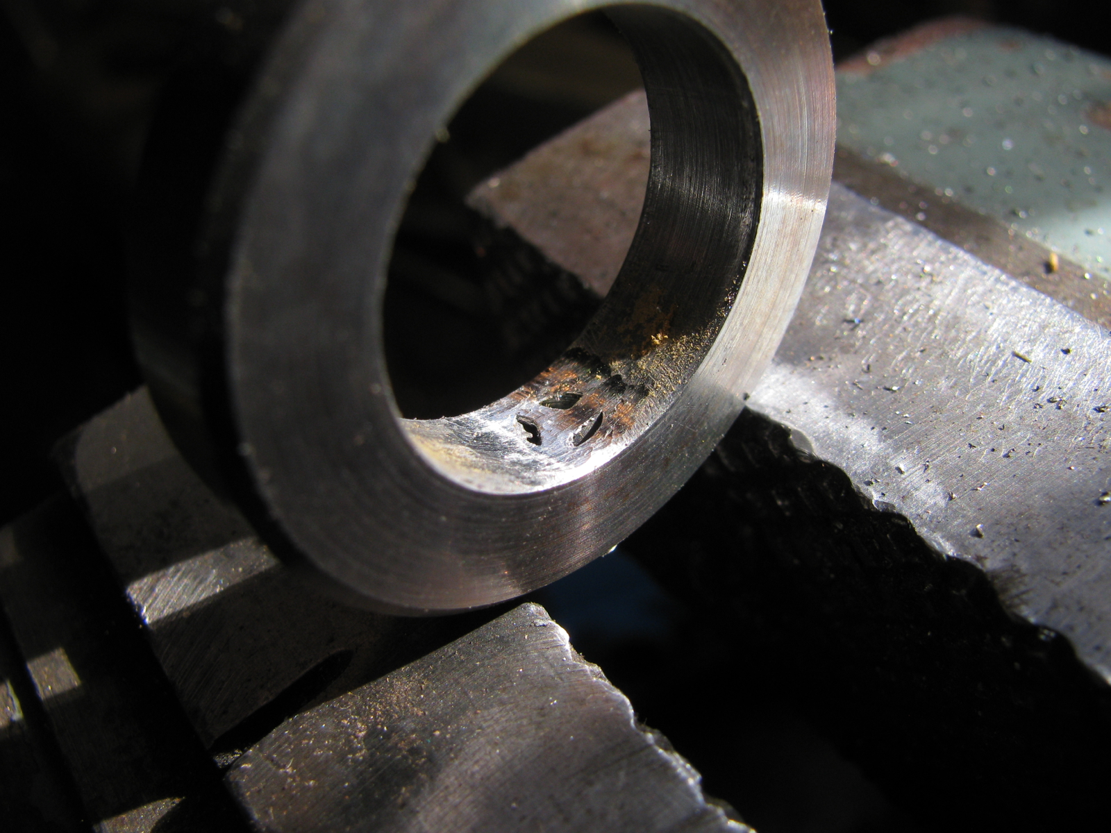
I was so pissed that i broke a tap I didn’t get the new hole exactly centred on the collar. Too bad, thats the way it is.
Enough of this for today.
Vanagon – rear bumper build news
Posted by albell in syncro, vanagon, vanagon mods on February 12, 2014
Man, with this damn bumper build, have I been dogging it or what? Here is a post showing just how little I have done over the last few months.
I have the actual bumper more or less in the shape I want it. So I went on to building the swing away tire carrier. I drilled a hole through the driver’s side corner and welded in a section of aluminum tubing.
On the top surface I ground things down flush. What I haven’t shown is the heavy duty bracing I did to the bumper in this area.

Skipping ahead (too lazy to rearrange how the pics were inserted), making Delrin bushings.
The shaft is a bit of 1″ stainless rod let into a bit of 1/2″ stainless plate, welded to rod on top surface.
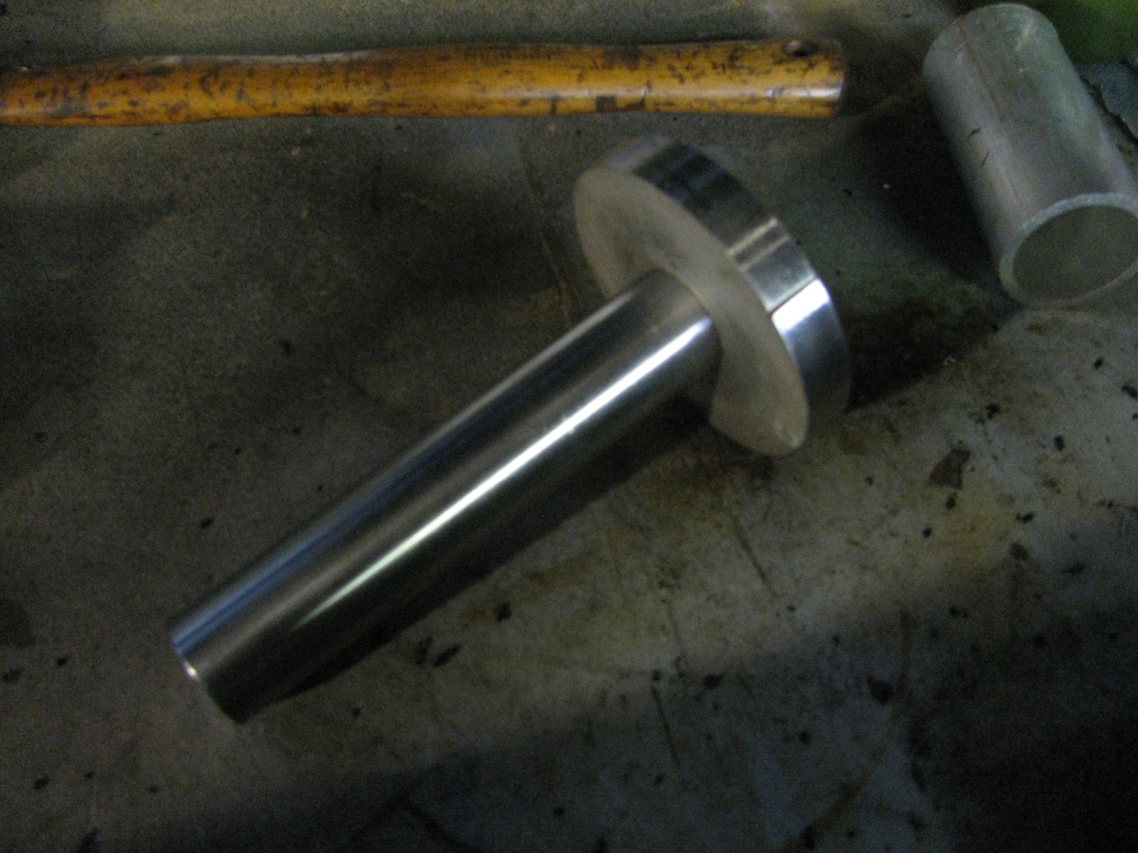
End of rod drilled and tapped 1/2″ nc.

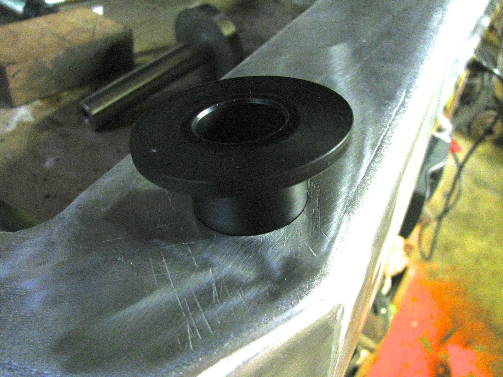
Bushing for top of tube.
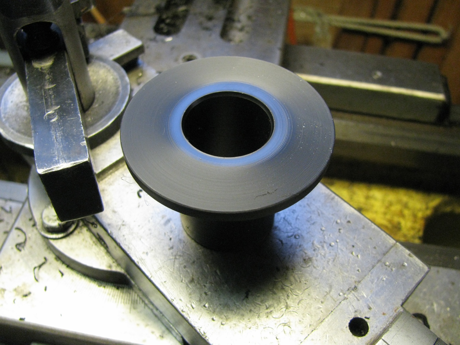


Bottom bushing is similar to top bushing but has a smaller flange. Here is top bushing being inserted into tube. The fit on the stainless shaft was a nice sliding fit, but the fit into the tube was tight. This resulted in the shaft having a very tight fit into the installed bushings, too tight really, so I had to take shaft out and take off a couple of thousands (inch).
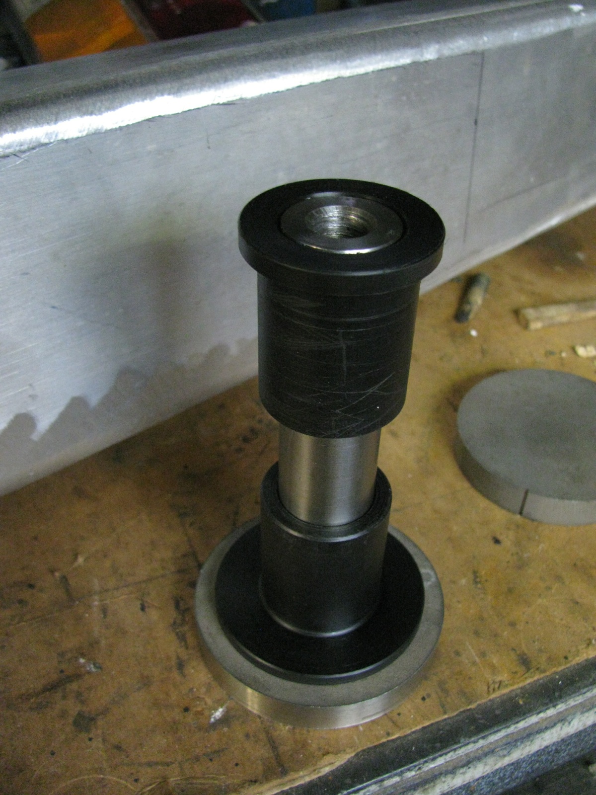
Oh here we have the bottom bushing being inserted.

Just to be clear, this shows how the bushings fit on the shaft.
Skipping ahead again… today I offered up the bumper to the van. Bear in mind the bumper is sitting on the stock bumper mounts. I will be making new mounts which will move the bumper closer to the van by about 1.5″. Please keep that in mind when you look at the pictures, it is important.
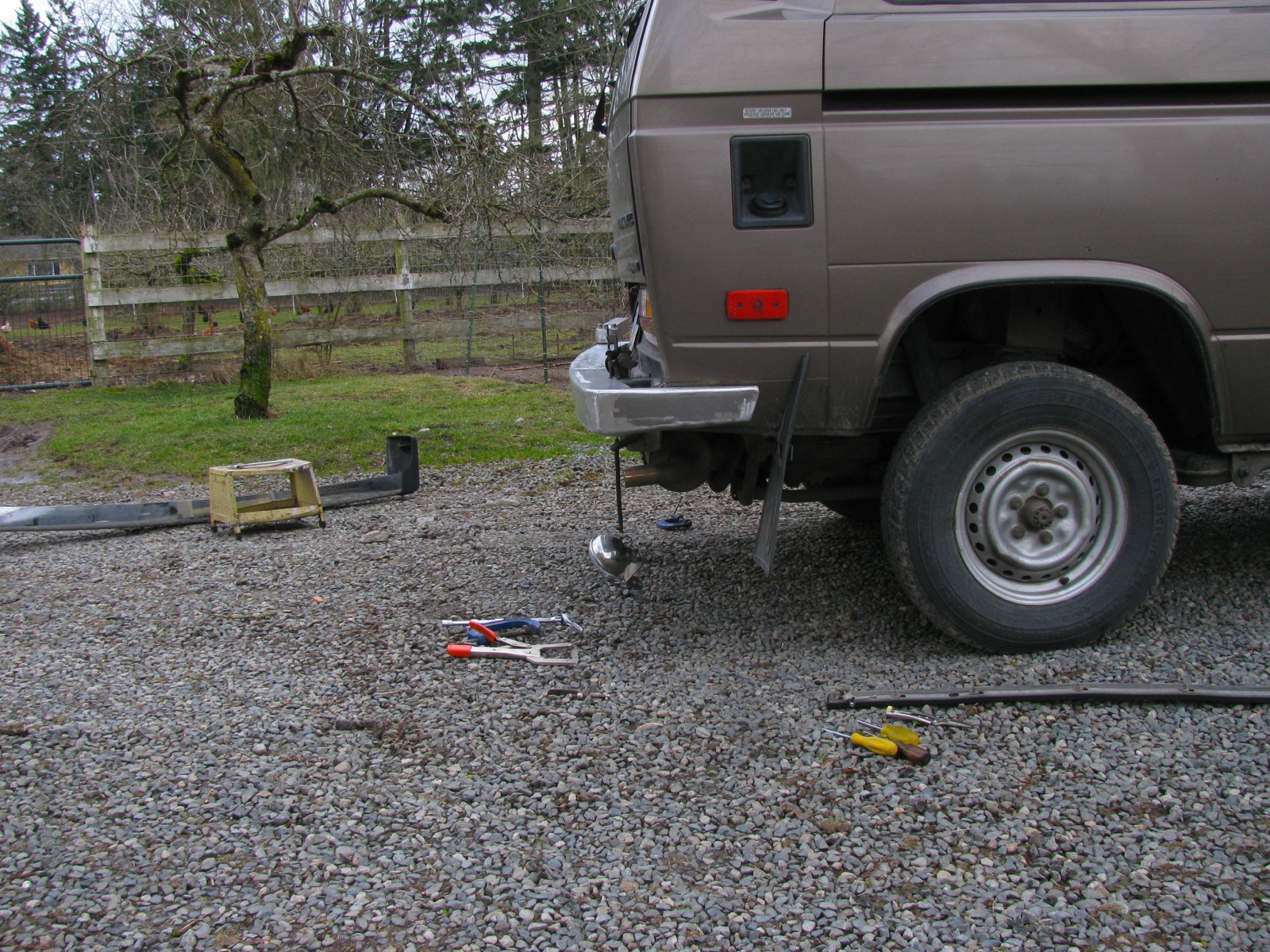
You can see the swing away arm installed. More on that arm further down. But right now see how the arm hits the bumper? I did machine things so that the mounting surface was parallel to the arm so either the bumper has a curve or the tube welded into the bumper was not 90 degrees to the bumper top surface. I think the latter is correct. I will mill the arm mounting surface to correct this.

I’m liking the shape of the bumper more and more. I wasn’t pleased at first, but I think it is ok. If i had to quibble I would say the end caps are too thick. That’s Lily, one of our two dogs, looking very bored with what is going on.

Ok, time to explain the arm. I had some water jet off-cuts, 1/4″ 6061 aluminum, that had curved ends. And the ends matched the radius of the stainless disk welded to the shaft in the bumper. I cut the off-cuts to fit inside the arm and ground down the ends to extend the radius around. I then stacked and inserted into the arm (2″ box, 1/4″ wall, 6061 aluminum) and welded them up. Then I drilled 3 holes for 12mm cap head bolts and threaded 3 holes on the stainless disk to match. I’ll try and remember to get some pics of the end for the next update.
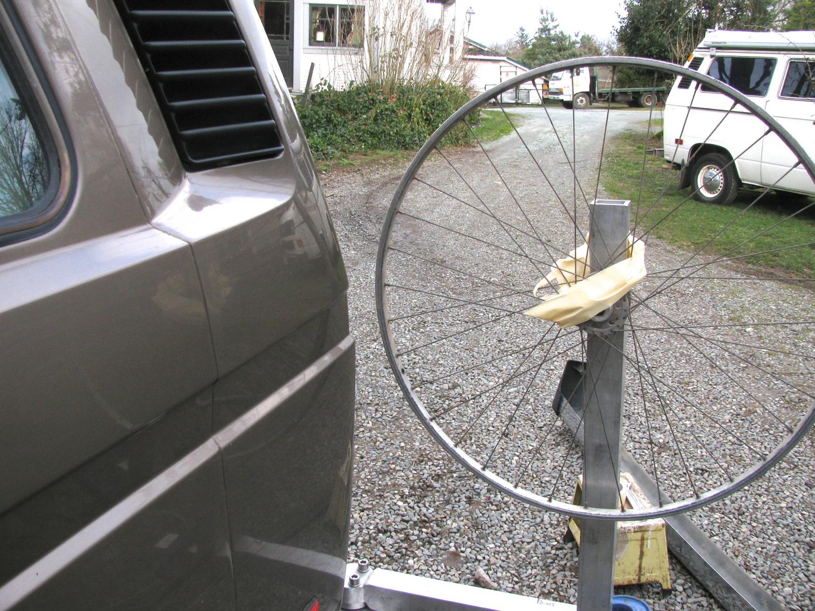
Now to determine where the upright should be positioned on the arm. I used and old bike wheel (25″ diameter) to help me decide. Now remember the bumper is sitting further out than its final position. So if I welded things up as shown, the upright would hit the hatch.

Figuring out the lateral position. Have to avoid the tail light.

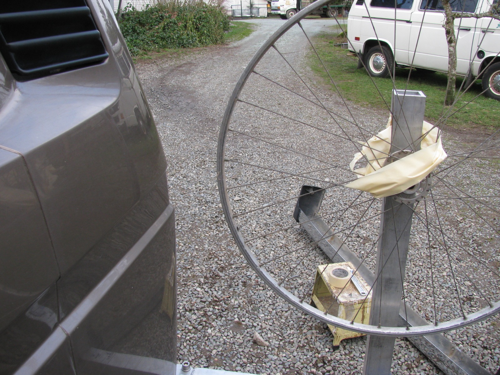
And have to make sure there is clearance when arm swung out to the side. Too close here.
So moved the upright inboard about an inch.
Better clearance when swung out.
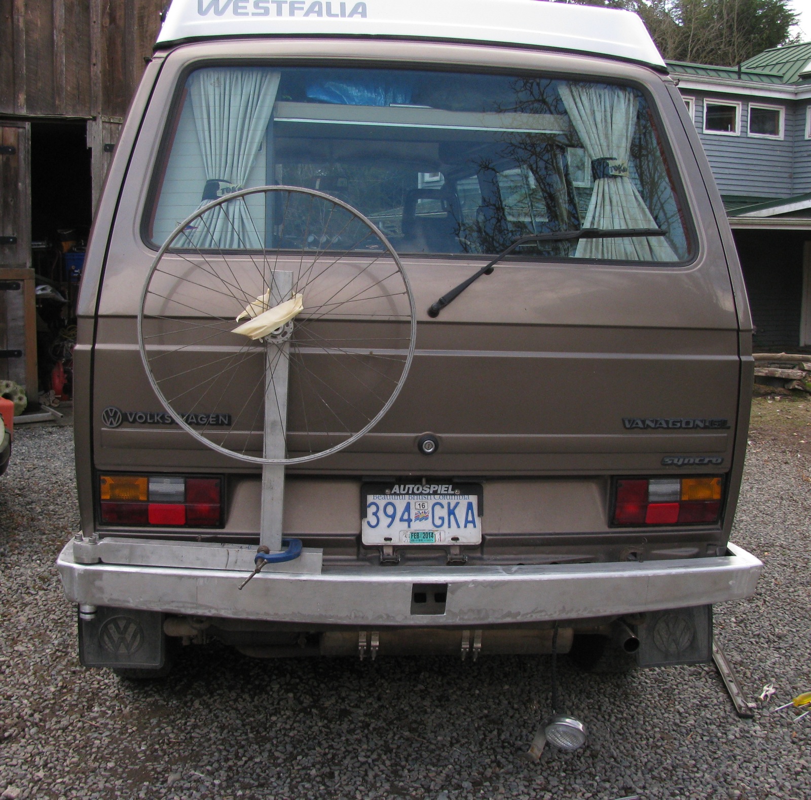
But still too close to hatch.

That means relocating the upright to the rear face of the arm. Not as tidy hand will mean some re-thinking of my latch/arm securing set up.

All for now, I really have to make the bumper mounts and do final welding of the trailer hitch sub assembly (which is hidden inside the bumper). That sub assembly will provide more support to the bumper – I’ll be screwing the aluminum down hard to it.
Vanagon – measuring axle runout
Apologies for the dearth of postings over the last month or so. I have been doing a little Vanagon work but nothing that was ready to blog about (I’m looking at you, Mr Bumper Project). This post is an effort to get back on track.
I made up a spare axle (rear) with cv joints and boots some time ago and carried it around in the van thinking it would be a talisman against breaking an axle or cv joint during one of our logging road trips. Additionally, I had made some end caps for the cv joints so the joint could be all greased up and ready to go. Good friend Simon envied the idea so I gave him the assembly as a Xmas gift.
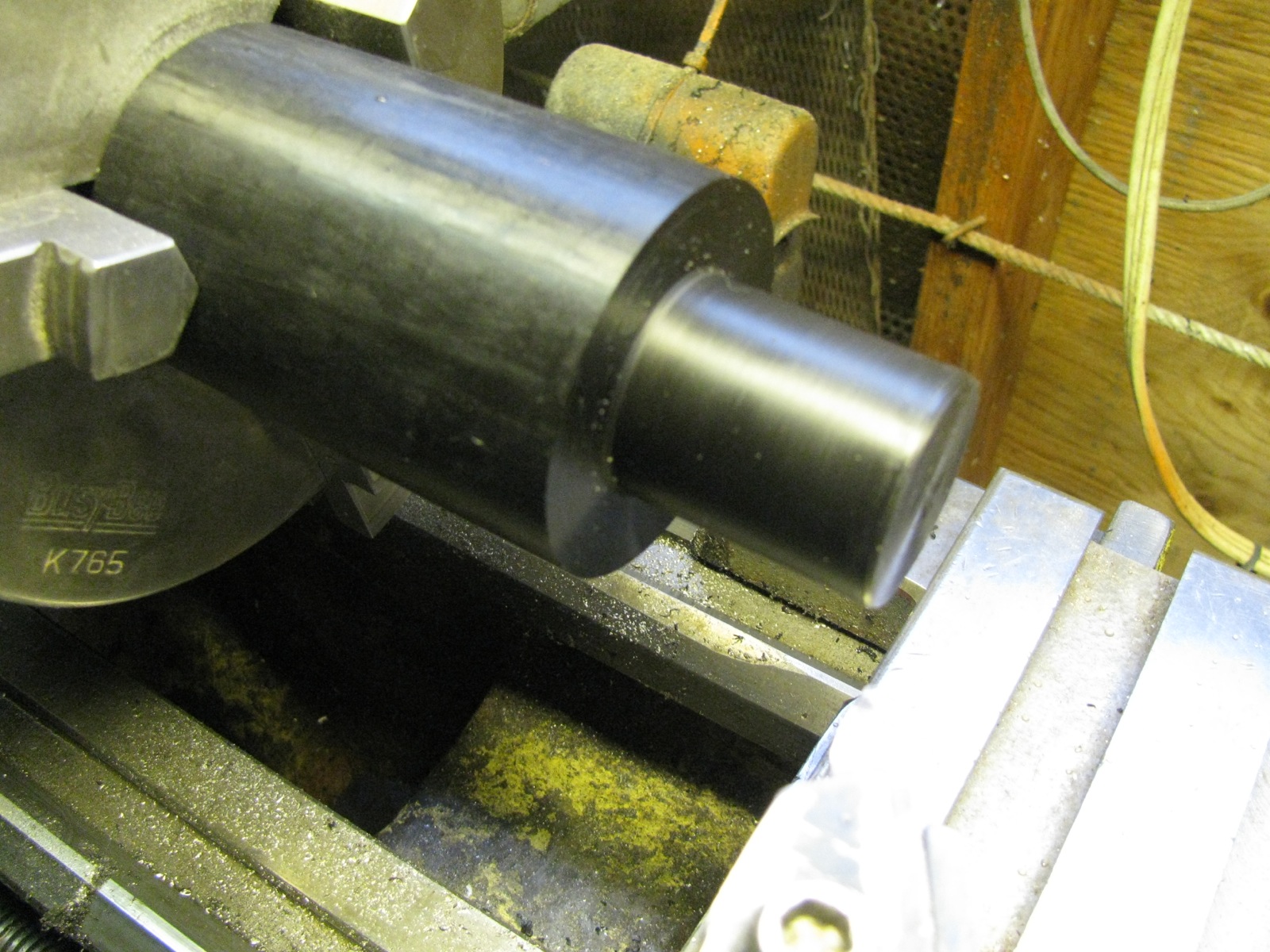
I ad another spare axle so the other day I dug it out and started to make up another spare assembly. I stripped it down, degreased the shaft, and took off the old paint and rust. I put the shaft on the lathe, tailstock and centre supporting the far end, to make painting easier. Yeah, I know, pretty sloppy habit to paint something on the lathe. But I covered the lathe to protect against overspray, put the lathe in back gear and had the shaft rotating as I sprayed the paint.
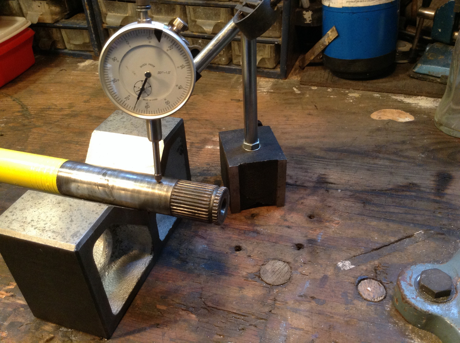
As I was doing that I noticed that the shaft had a bit of runout, i.e. it looked a little bent. Today the paint was hard enough to allow me to measure just how much runout the shaft has.
Shaft was supported at each end by V-blocks and the dial indicator positioned roughly between. I rotated the shaft by hand and watched the dial indicator. About a 0.013″ runout.
I did the same at both ends, one end it was around 0.003″ and the other end about 0.002″.

To be sure, this was a very quick and dirty way of measuring the runout, and to tell you the truth I have no idea if this is an acceptable amount of bent-ish-ness.
