Archive for August, 2013
Vanagon – iPad mount – MkII
Posted by albell in metal working, metalworking, vanagon, vanagon mods on August 29, 2013
At the end of my last post, the beginnings of a trailer hitch, I showed 2 pics of my iPad Mini mounted on the dash. It was a start, a Mk I if you like, to see if I liked the position. I used some found coaxial wire, about 0.6″ diameter, aluminum wire core, polyethylene, aluminum sheath then vinyl cover. Or something like that, the point is the stuff bends and holds. It doesn’t bend back and forth forever though. Anyhoo, that and a swivel mount I made (aluminum and teflon on the moving parts), some plumbing fittings, and a pretty crudely made plate on the ashtray hole.
I did try mounting to the inside of the ashtray, and I managed to do it. But the ashtray wouldn’t stay in place with all the weight and I broke the damn thing trying to solve that problem.
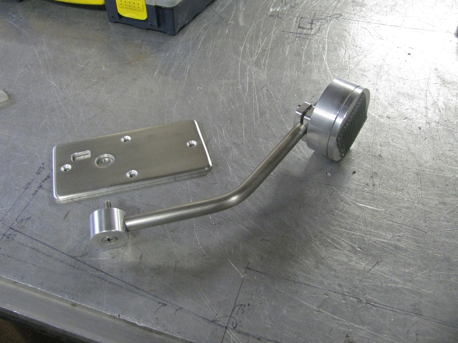
I didn’t like the high position of this mount so back to the bench. More bits of scrap aluminum, some 0.5″ stainless tubing, and further dicking around ended up with something that looks more surgical than automotive. Man, I need some sense.

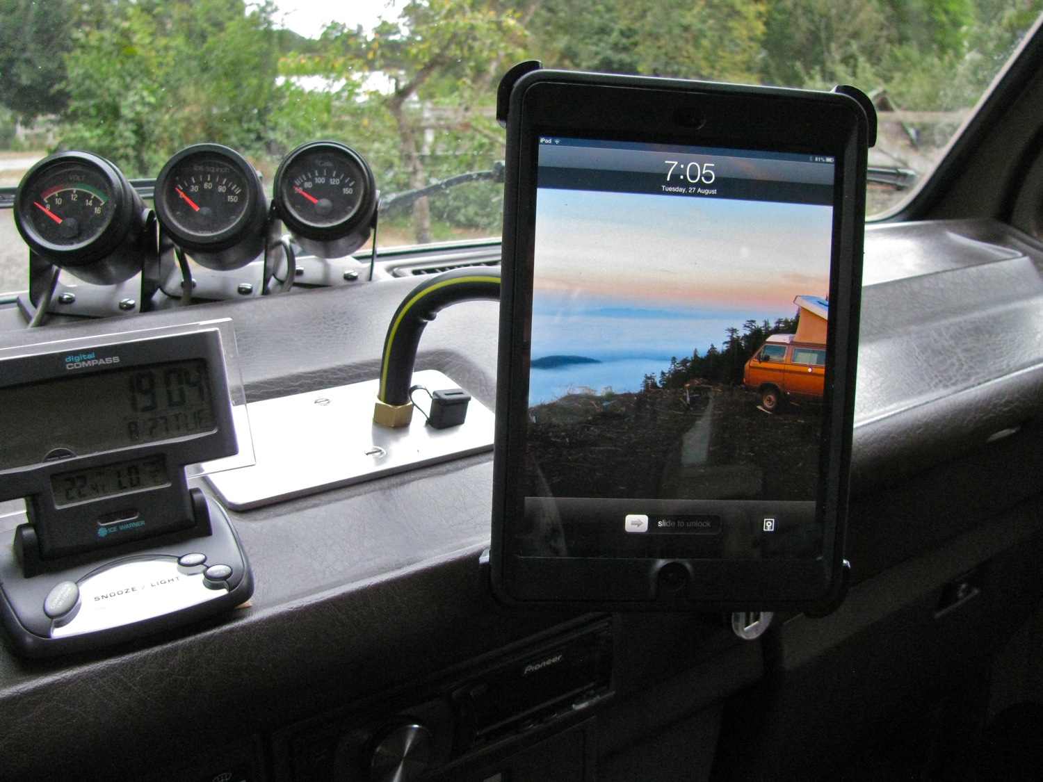
The swivel mount has some Velcro on it. I’m using that to connect to the Otterbox Defender case (the cover part that doubles as a back and a stand). Velcro is not great for this, but was all I could come up with for now.
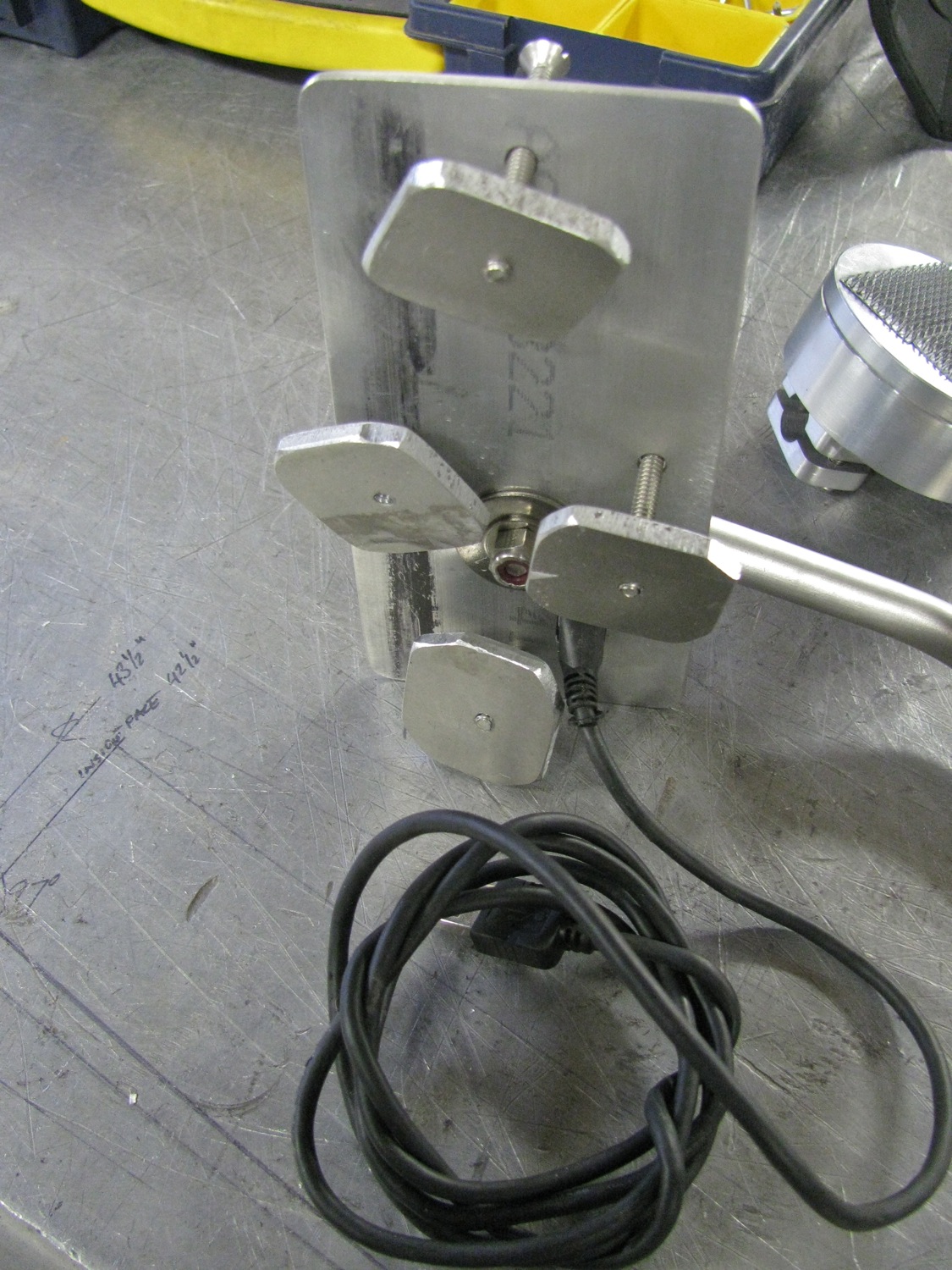
Crude tabs to hook into dash. USB extension cable for connection to stereo head unit.
I made the arm a bit too long, I’ll trim it back. I like this position better and yes, you can still shift gears.
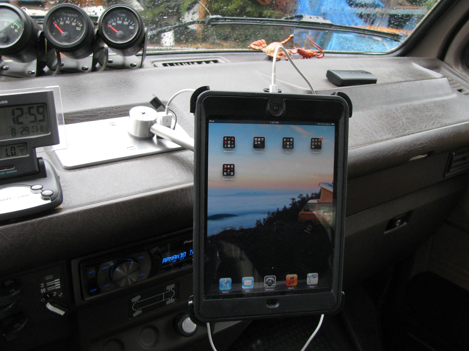
Swivels to landscape.

I agree, it is a bit clunky. And what to do with the cable? I don’t want to run it inside the tubing. Maybe I can figure something out to make it less untidy looking.
vanagon – bumper build – starting the hitch
Posted by albell in metal working, metalworking, syncro, vanagon, vanagon mods on August 27, 2013
I’ll blame good friend Simon for the recent dearth of posts, you might understand why at the end of this post. The bumper is pretty well roughed out and before I can finish the aluminum I need to make a trailer hitch to fit behind. I do have one of those tow loop mounted hitches but I want something stronger.
So the idea is a receiver style hitch with a crossmember behind the bumper welded to the stock bumper mounts (which I will modify and extend further I the frame rails), and the receiver part of the hitch coming through the lower part of the bumper. I’m not being very clear, sorry, it all make sense as I post my progress.
And what progress have I made? I’m going to pad out the little work I have done.
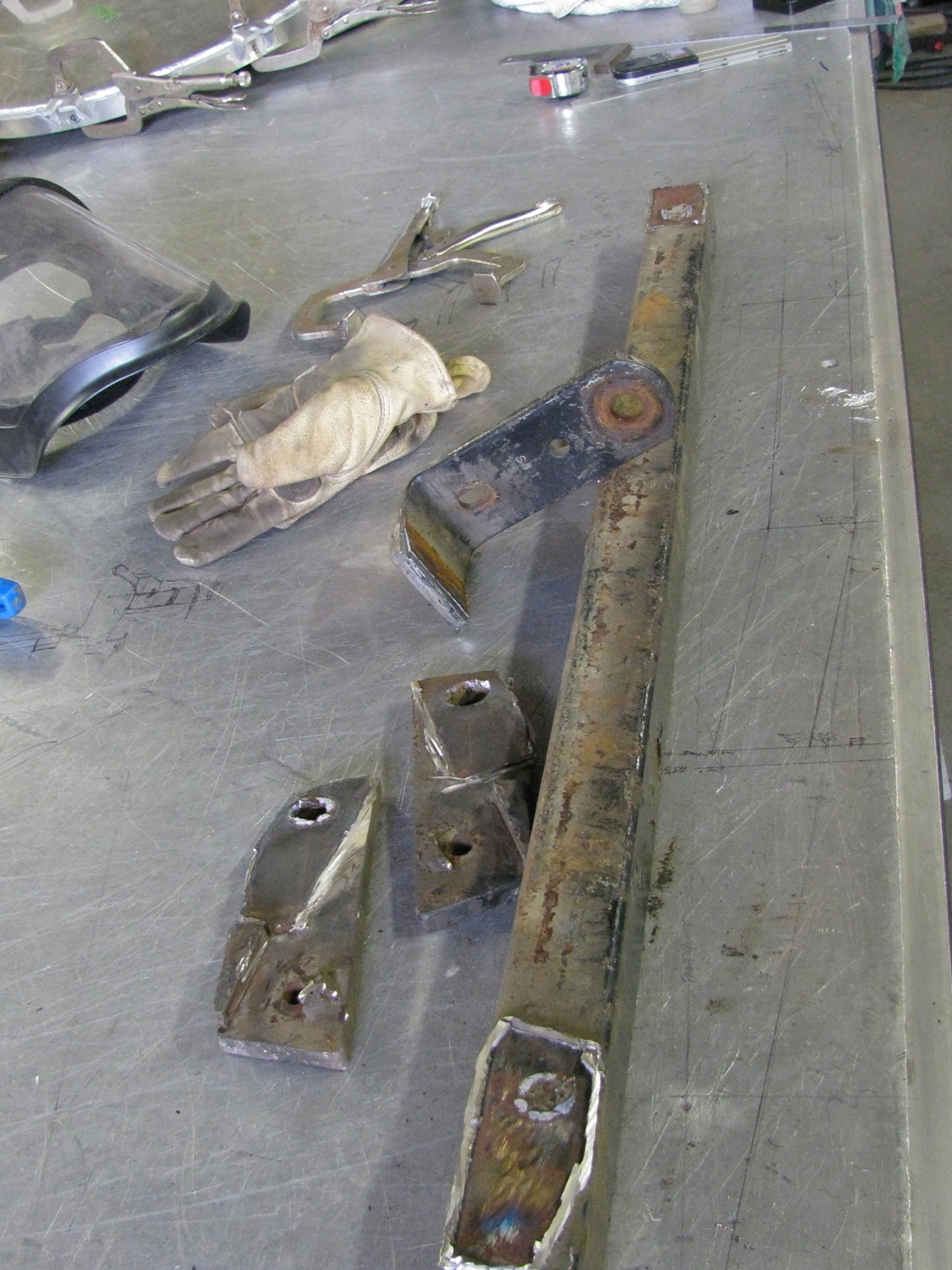
Well, here is my existing hitch and the bits for the 2″ receiver.
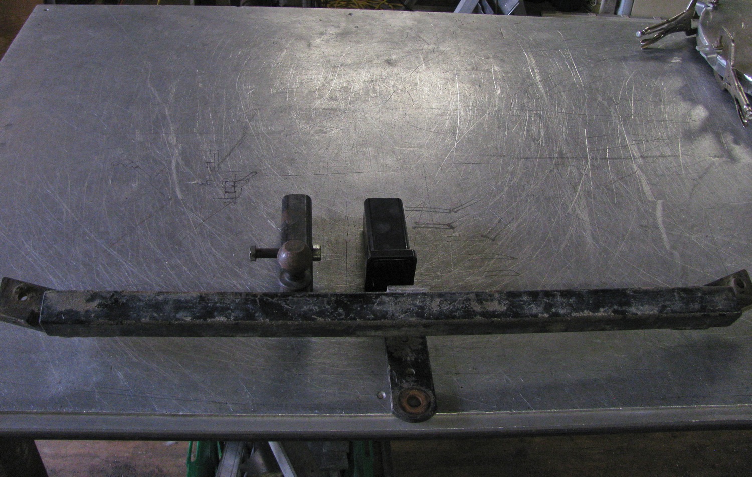

I cut the bits off.

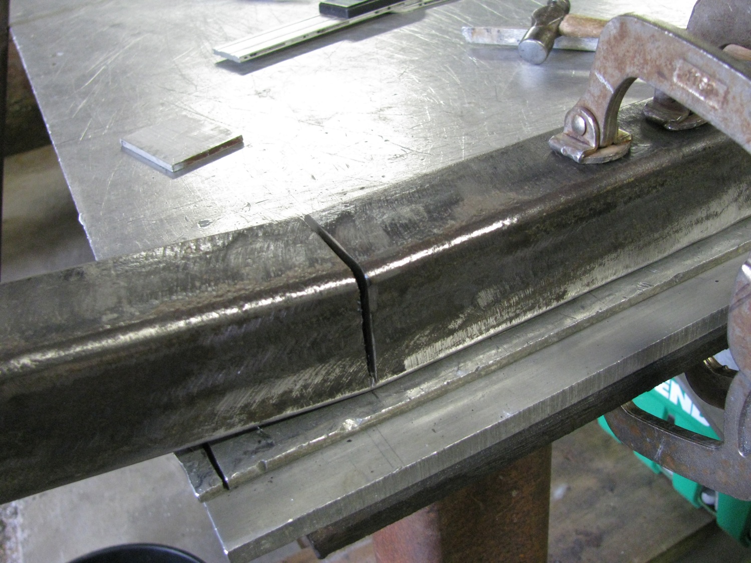
I want to have this bar sit as close to the inside rear face of the bumper as possible, To do that I need to make a couple of bends. Pretty sloppy work cutting “V” notches to make a 7 degree bend, I could have done better. Oh I did cut the tube in half before I did the notches.

Up it bends, leaving a big gap, grrr.
Get the idea of what I am aiming for?

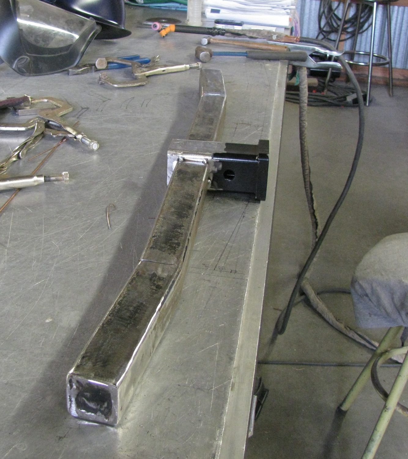
It might come as a surprise that I can’t stick weld very well. The MIG welder is set up for aluminum and stainless and very likely will never see steel. So until my welding teacher comes by to give me some stick welding pointers I TIG tacked the bends and other parts onto the tube. I used some rod to help me jump the gap with my tacks.

All tacked up and ready to start trial fitting to van and new bumper. Oh, btw, I will add some reinforcing plates between the receiver and the main tube.
So why is Simon partly responsible for me not posting more often? He gave me an Ipad mini. Yup, what a guy. I’ve been playing with navigation/map apps and I think I might post some stuff on that. Also started mocking up a mount to install it in the van. It’s a start, by no mean the final thing, but gives me some ideas.
Thanks again M&S.

Vanagon – bumper build – other end cap done
Posted by albell in metal working, metalworking, vanagon, vanagon mods on August 9, 2013
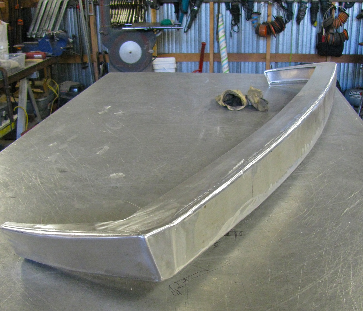
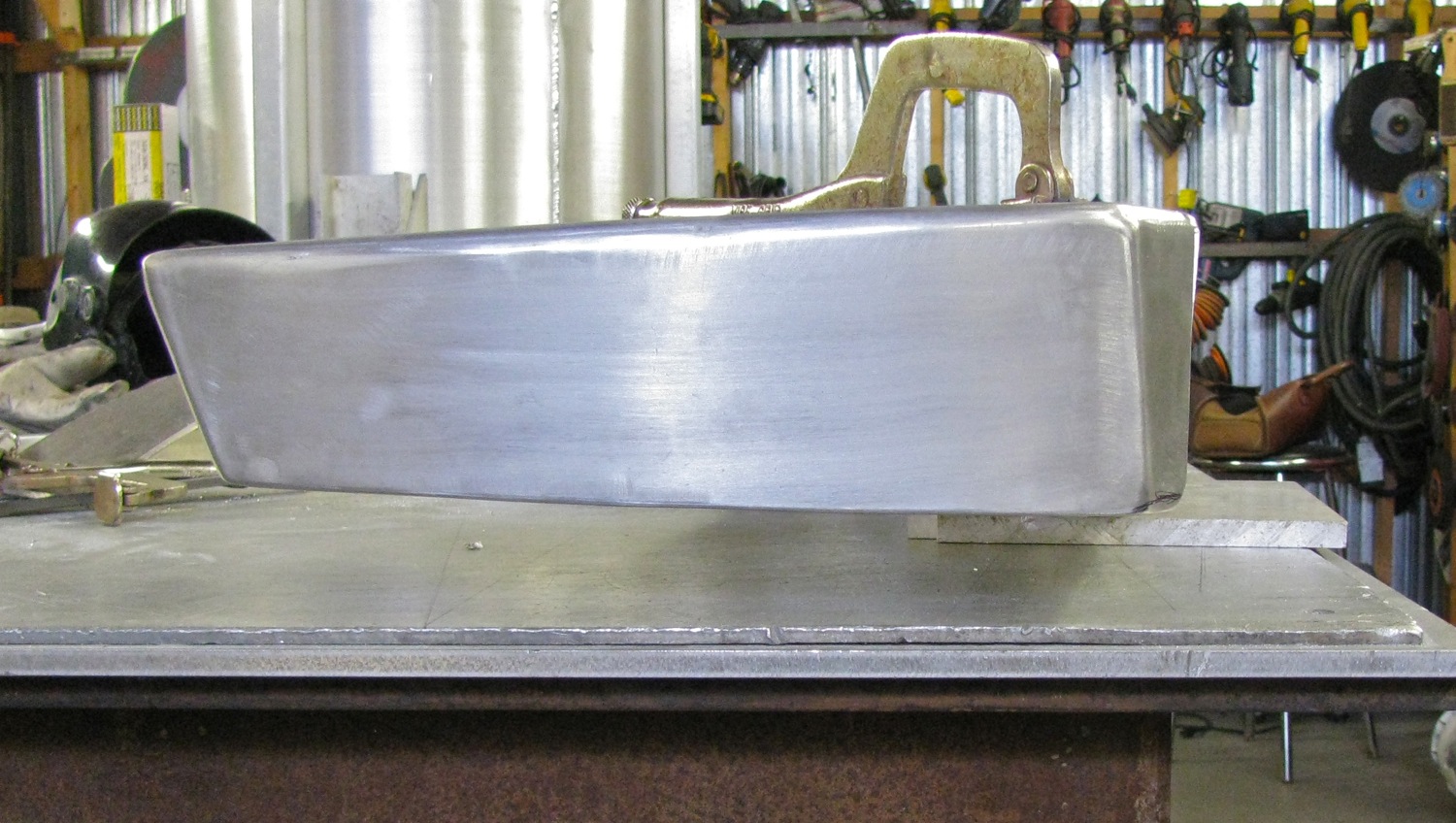
Update: I weighed the bumper as you see it below, it’s 9.2 kg (20.3 lbs). For comparison, the stock chromed steel bumper, minus plastic end caps, weighs in at a svelte 5.6 kg (12.3 lbs)
A little progress made on this project. Made up a more or less matching end cap and also did some preliminary grinding out of the welds. What a chore this way of making a bumper this is. You understand don’t you, that this is me making it up as I go along, modelling (I can hardly say sculpting can I?) a bumper out of aluminum plate. Once I get a shape that I like and that works then I can take measurements and think about how you could make one easier and faster.

Vanagon – bumper build – fixing the endcap connection
Posted by albell in metal working, metalworking, vanagon, vanagon mods on August 7, 2013
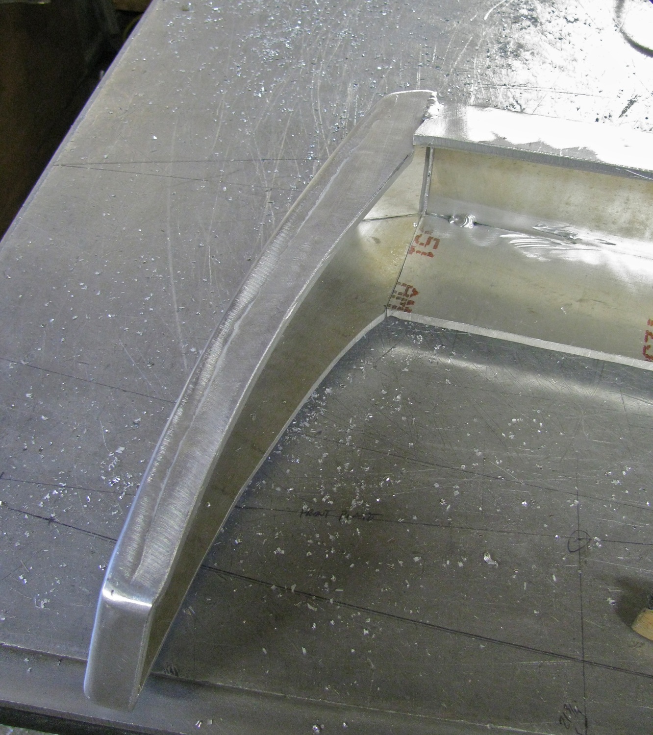
I really didn’t think through the bumper to endcap transition did I? Here is what my doodling around resulted in.
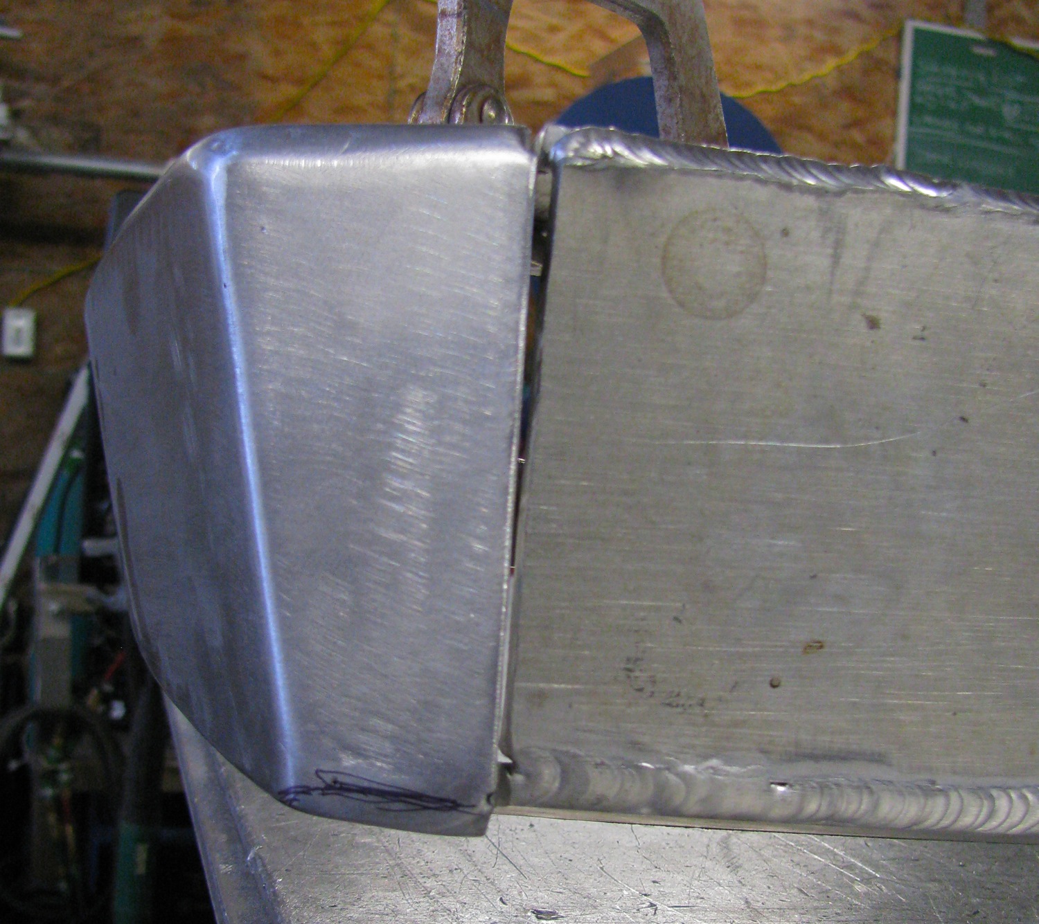
I have to be clear and say again that I’m winging it. I’m doing in aluminum what I should be doing in cardboard or thin plywood. So to fix the blunder, I cut the endcap up a bit, angled the bottom plate to match the bumper bottom plate, added another filler piece then welded it up and roughly smoothed things over. It is a lot better now, this might be the one to keep.

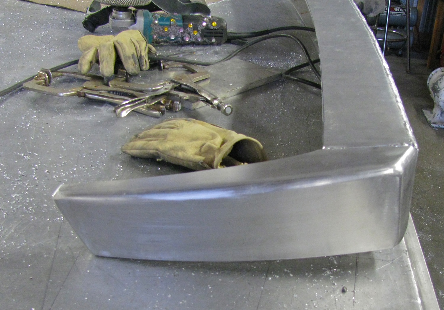
I didn’t take too much time grinding the welds, but enough to get the idea of how I want the corners to look.

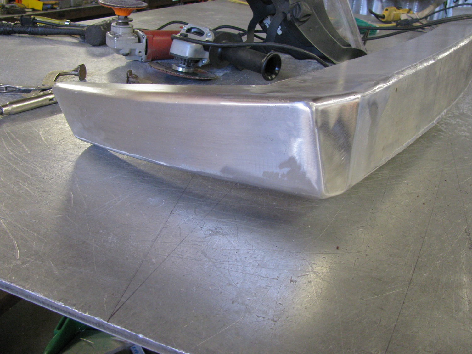

Both bottom plates, bumper and endcap, meet up a bit better. I’d like to radius or smooth out the inside corner also.


Next thing to do is to double check fit on van, smooth out some wavy edges and corners, then make a matching (ha!) endcap for the other side.
Trip – quick look at Loup Creek
Just back from a short overnight trip. Our goal was to see if we could find a camping spot on Loup Creek (a tributary of the Gordon River). I’ll leave it up to the reader to discover just exactly where we ended up.
July set records here for the lack of rain (it did shower for a couple of days at the end of the month) and we were worried that gates would be closed on some logging roads. Turned out many gates were closed and that stopped us from exploring some other spots before we got to Loup Creek. We drove up some fairly steep and rough roads, but at the end of them there was neither a good view or a creek or lake. For some reason I didn’t take any pics of the steep roads, I guess I was distracted by the search and the road conditions. I have to say that the little mods to add some more ground clearance on the van really paid off. No more scraping the spare tire carrier or the trailer hitch when going over the ditches cut across some of the minor logging roads. Those roads can be fairly steep (+20%) and the road surface is loose sharp rock.
The only pic I took of this part of the trip (not steep and not rough)
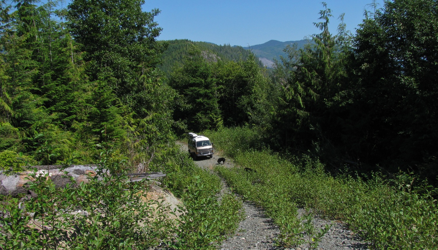
So off we went northwest alongside the Gordon until we found the old, abandoned Forest Service road. Moderately steep climb, loose rock, few over hanging alders. Toodled along until we came to the first bridge over the Loup. This was a bridge built to last – large concrete abutments, 2 giant I-beams spanning, and precast concrete sections as deck. Deck about 30 feet above creek. Other side of the bridge was pretty well alder choked, and the roads led to nowhere interesting so we decided to continue upstream to find the second bridge. There was this sign just up the road.

Then there was a steep section and the surface of the road was made up of larger than normal loose rock. At this point the van started to miss and buck, just the same thing it did at the end of our last trip. We barely made it up the steep section, van bouncing, tires slipping. Not that much fun with a ditch on one side and a very steep drop down to Loup Creek on the other side. We had to drive on a kilometre or so before we could find a level spot to stop. I won’t go into any thoughts about why the van was missing and bucking in this post, but we let the engine cool down (it was a hot day and we had been working it hard) to see if that made any difference. Well it didn’t and even thought I really wanted to go on to find the second bridge we decided to turn back and camp at the first bridge.
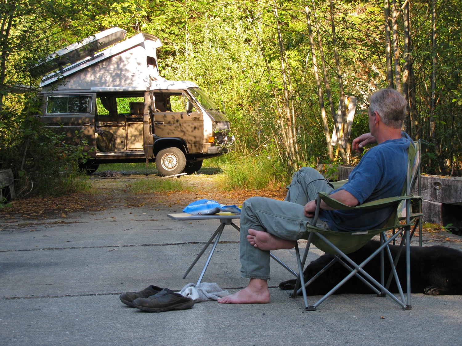
It really wasn’t a bad place to camp. Secluded, beside a creek, bugs not *that* bad.
So here I am sitting and thinking. Am I marvelling at how good the classic Thule Combibox 250 looks on the van? (that’s for you Phil Z.). Am I enjoying using the table mod? Am I enjoying a drink and some potato chips? Or am I wondering why the van engine is acting up?
All of the above 🙂
As the creek runs pretty well north – south at this section, and as the sun was in the west, I couldn’t get very good pics of the creek from the bridge. I did get a pic of the van lit up by all the led strips later that evening, for Jerome.

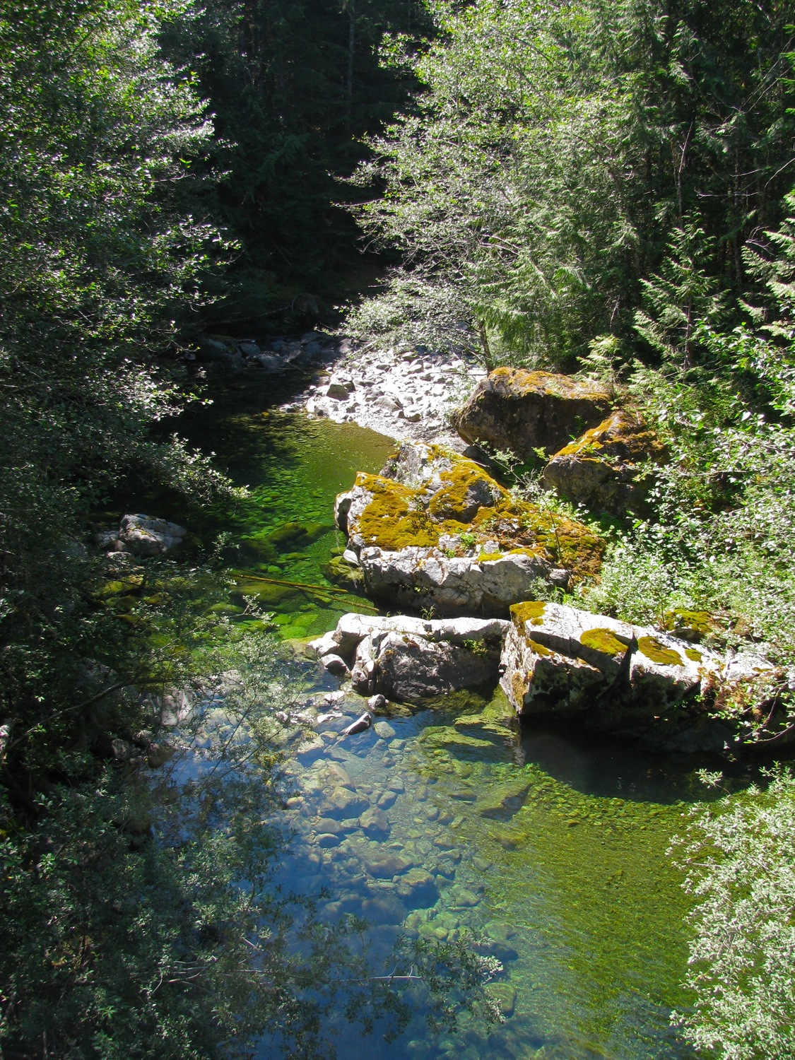
About 11 am next morning, sun made it down into the creek. Still hard to get a shot, the river rocks reflect a lot of light
Looking upstream (north).

And downstream.
We packed some food and drink and clambered down to the creek and walked up stream a short distance. My wife and Jake found the way down.
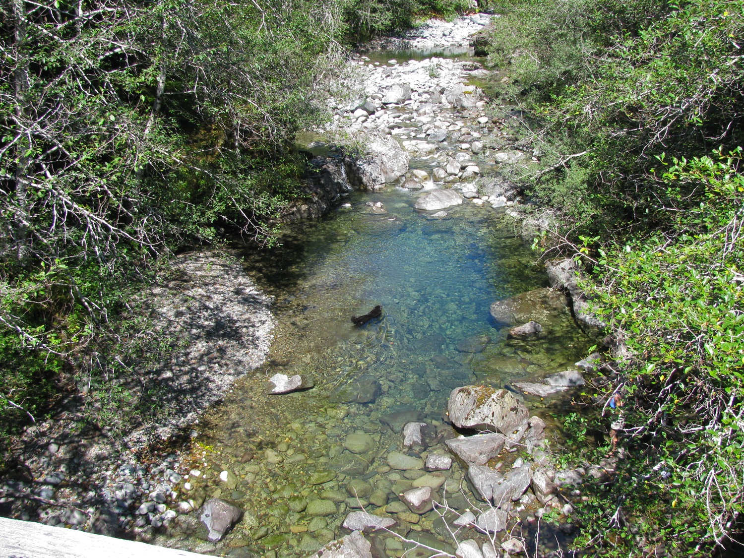
There are some small trout, and perhaps salmon fry?

You might be able to make out the bridge.

And about 6pm we packed up and drove home. Van bucking came and went, no rhyme or reason. Ah well, that’s something to figure out later. It didn’t spoil a nice little trip.
Vanagon – bumper build – end cap attempt
Posted by albell in metal working, vanagon, vanagon mods on August 2, 2013
Didn’t get much done today, just worked on one end cap. I had thought about making a mock-up from door skin or cardboard but instead I went ahead mocking up with aluminum (1/4″ for top and bottom, 3/16″ for the face plate).
The 3/16″ face plate (vertical plate) was from a bit of scrap that was curved, large radius. I cut some 1/4″ plate for top and bottom and tacked them on. Then clamped the affair to the bumper.

It’s a trick transition, and you will see later that I still haven’t figured it out. I cut a bit of 1/4″ to fill the hole.
I couldn’t resist rough grinding a radius on the welds.

Another view.

Side view.
The corner filler bit is obvious in this pic.

I’m quite there yet, am I?

“if you can jump it, I can weld it”… ha!
I tacked the end cap to the bumper so that I could remove the clamp and took the bumper out to the van to see how it fit. Up until this point I was only guessing the dimensions of the end cap – I wanted it to end up about an inch behind my mudflaps and about 1/4″ from the body. Turned out I had to thin the endcap down a bit, was hitting the body.
So it was “MIller time!”! One tool that gets a lot of respect and care in use. Nasty bit of work but cuts the aluminum nicely. What’s with the rust on the blade? Must have got splashed with water, and we don’t put any oil or the like on tools that will be touching aluminum or stainless for fear of weld contamination.

Slimming things down.

I think it looks nicer than the first version.

And it fits to the van like I want it to.
I will have to zip cut the front of the endcap and re-form it to make the transition to the lower plate of the bumper. But I’m liking how things are going.
Vanagon – bumper build part 2
Posted by albell in metalworking, vanagon, vanagon mods on August 1, 2013
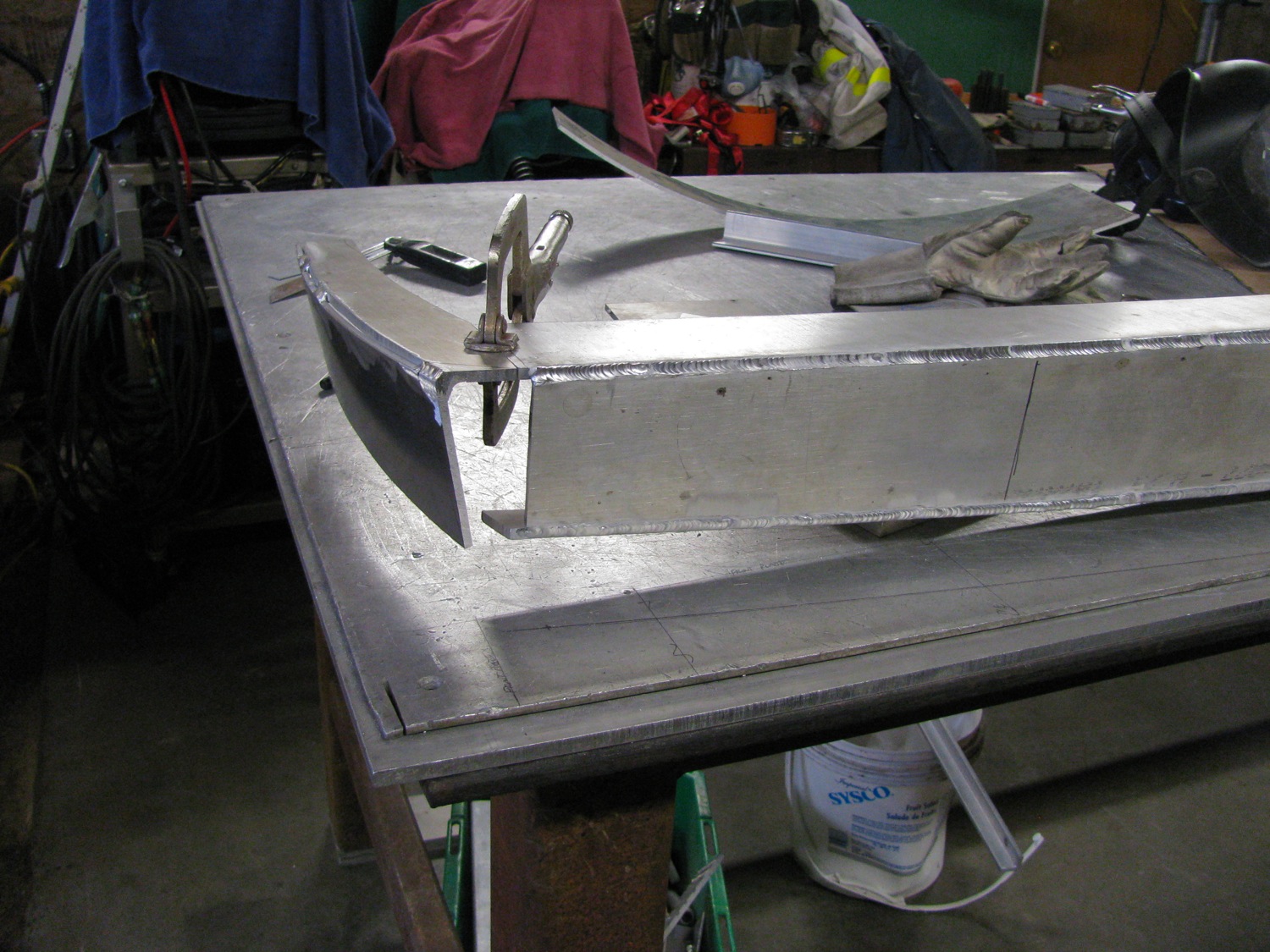
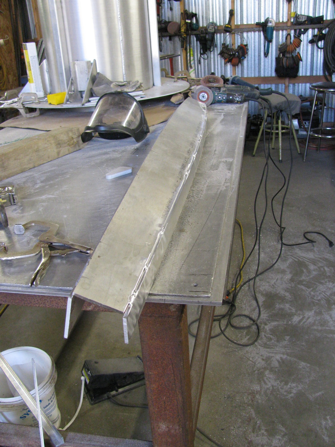
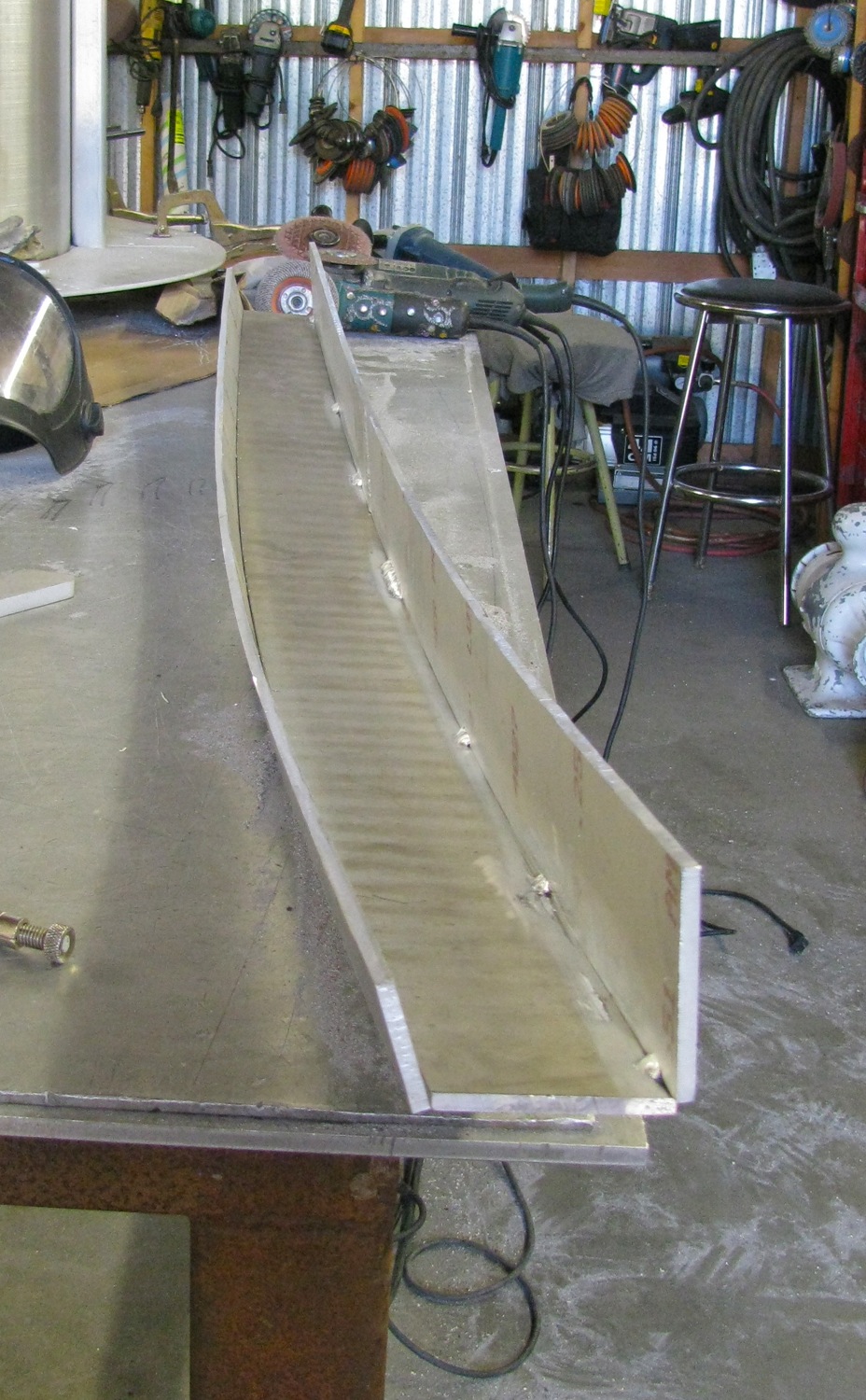
I managed to tack and weld out the 3 main parts of the bumper. It was a little bit of a struggle pulling the bottom plate into position (inside edge to inside edge with about a 1/16″ overlap). I ended up TIG welding all the joints. I didn’t like the MIG welds I made on a test piece (I don’t have many hours on the machine). I’m not saying that my TIG welds are very good, but at least I got some practice. In any case, I’m going to grind down the welds to make a rounded or at least a beveled corner. I haven’t finished fairing the free edges of the top and bottom plates yet.
Tacked up.

Outside tacks on the face to bottom plate joint.
Inside tacks on top plate to face plate.
Then on to my inconsistent and amateurish weld out.
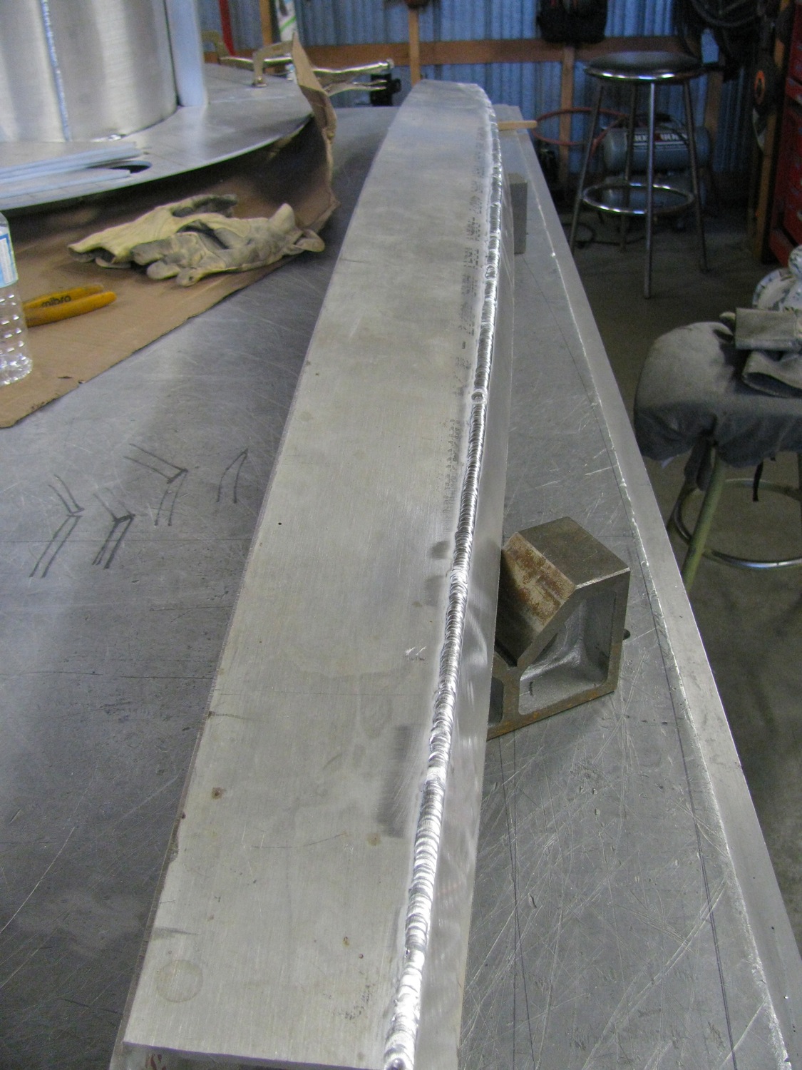
All done, top and bottom plate welded on.

I’m rubbish at estimating weights, but I’d guess around 10 kg as is.
Vanagon – rear bumper build
Posted by albell in metalworking, vanagon on August 1, 2013
I figured I need to post what I have done so that I have more reason to finish the job. I want to make new bumper, front and rear. Not because the stock bumpers are damaged or rusty, but because I want bumpers that are a bit stronger and will be able accept a spare tire carrier on the rear and better aux. light mounts up front. And just because I want to make some bumpers.
It’s a project that never seems to get really going nut here is the progress to date.
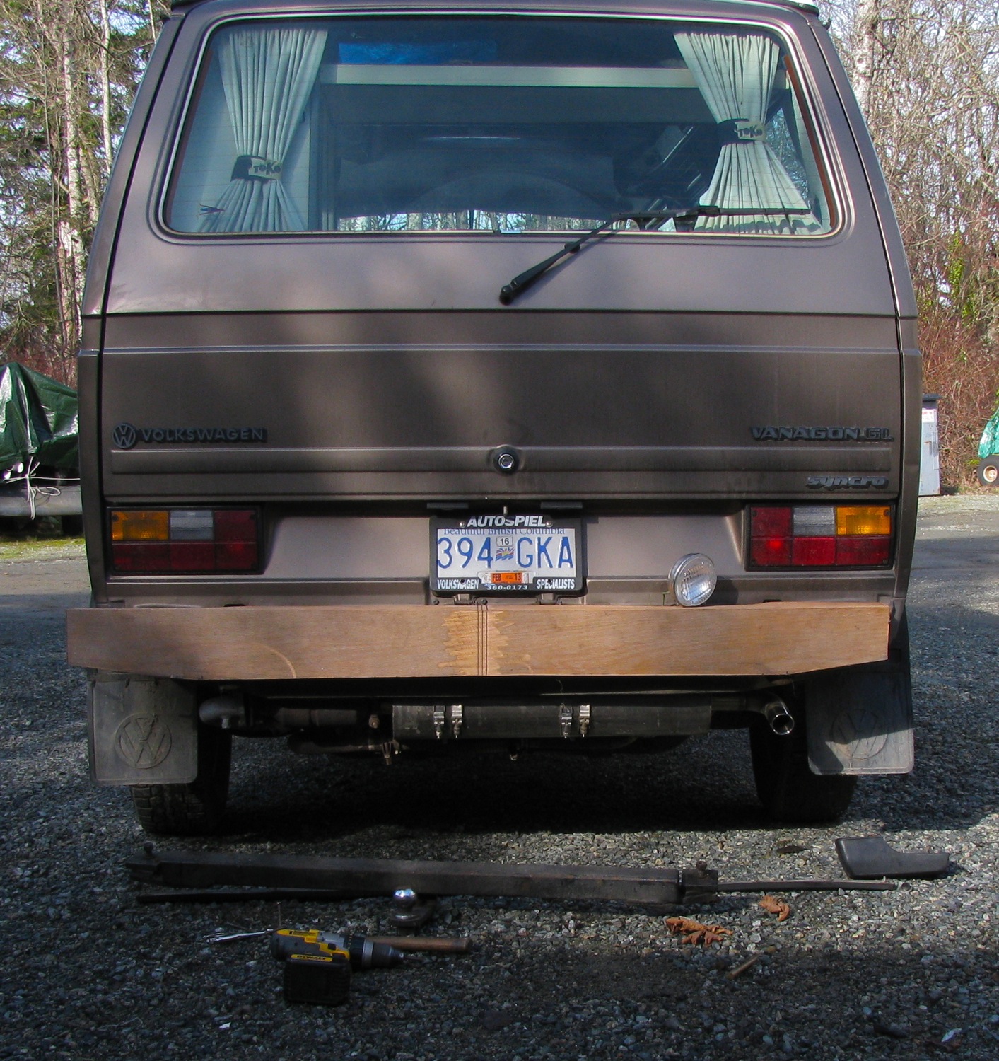
Last year I fooled around with making a mock up rear bumper out of door skin and hot glue. I came up with a shape that to be honest was the best I could given the brief of it being simple, slim (not bulky like some aftermarket bumpers – yes, I’m looking at you Go-Westy) and easy to make. The door skin and hot glue construction makes it easy to add or remove material and have a relatively solid model to play with. I have a hard time visualizing an object from drawings so I tend to make a mock up (or remake the real object).
I started with a slim bumper design, very simple with a flat top surface (to make standing on bumper easier), a gentle curve on the rear vertical face that closely mimics the stock bumper, and a curved lower edge rather than straight lines to where the bumper caps would be. I took the first design over to let Simon have a look. His tastes lean a bit more towards a heavier bumper so I stuck on more door skin and made it so.
BTW, in the mock up pics the bumper is shifted to the left due to interference between the stock bumper mounts and some wooden braces in the mockup.
I don’t like this at all.
I removed some wood, looks better. Probably would please Simon.

But I like ’em slimmer still. Ended up back to the original shape.

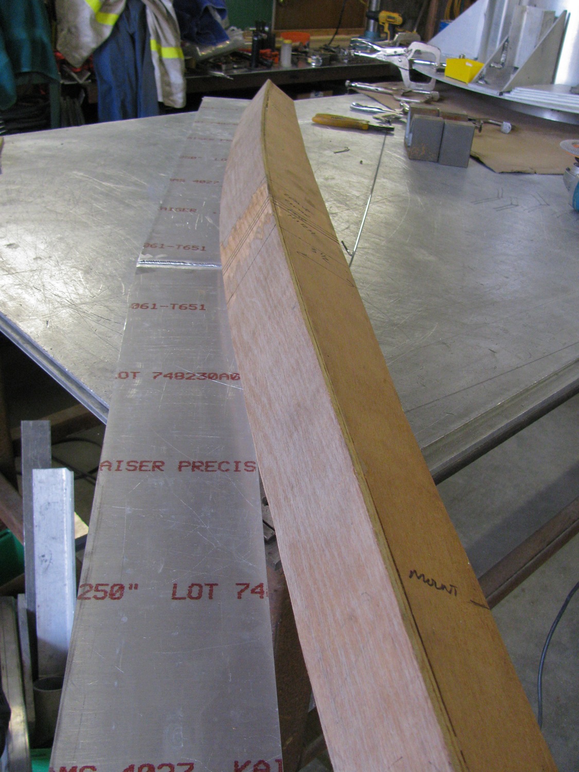
Right then, I’ve settled on the rough shape now what material will the real bumper be made from? Silly question, aluminum naturally. I’m using some off-cuts of 1/4″ aluminum plate (6061). I think that thickness will be plenty strong, especially when it is bent and welded up into the final “C” channel of the design.
I should mention that I took dimensions from the mock up and “projected” the 3 faces onto the top of the workbench. I used a bit of wood to fair the curves and picked up the shapes for the 3 main parts (top, bottom, rear face)h onto some polyethylene sheet. I could then tape the pattern onto the aluminum stock and use a prick punch to mark the shape on the aluminum. But I’m getting ahead of myself, I have to weld some of the aluminum together before cutting out the shapes.
My lumpy and large TIG weld. In my defence, I hadn’t touched the welder for a couple of months so what little skill I did have seemed to have slipped away.


I’ve cut out the 3 main parts, rather roughly I’m afraid, and if I have time today I’ll try bending and tacking them up. I’ll need to make some internal braces just to make the weld up easier. I’ll TIG weld the tacks, then I think I’ll use the MIG welder for the final weld up. It would be sort of silly for me to TIG the long welds.
