Archive for January, 2013
Trip – overnighter, or looking for snow in all the wrong places
Edit: I forgot to post up some sort of map to give you an idea of where I was.
Google map ref to general area.
Rough placement of stops.

This past Saturday afternoon I decided to head off for an overnighter. I wanted to park in the snow, on some viewpoint, and relax. I headed to the area north of China Beach Park, just NW of Jordan River where I had a nice night there a couple of winters ago. The approach is logged much more than it was back then.

I hit snow, deep hard rutted tracks, past some parked cars (day trippers: X-country skiing and snowshoeing) and on until the ruts came to an end. Met a snowshoe wearing hiker who told me that trees were down further up, road was impassable. Ok, back down the road but turning left (east) before the hwy. Road wound along the side of the hill, came to this spur going up. It doesn’t look like it and the camera always seems to flatten things, but it is as steep a spur as you get, probably 25% slope.

No real view at top, so back down.

Kept on going, turned out I was heading up the west side of the Jordan river canyon.

On up to the dam and reservoir (view from the other side of this canyon in this trip).

Was getting darker, I thought if I couldn’t get a sunset, then I would find a spot for a sunrise. Went up a spur… ladder?

Turned around so sliding door facing east, got out to look around, and… dammit, voices from above me. Some guys yelling down from spur above that the gate would be locked tonight. The gate way back where I “turning left (east) before the hwy”. Was truly dark now, got down onto the hwy and headed towards Port Renfrew. I don’t know why, but both my headlights and aux. lights seemed feeble on the logging roads. I’ve used 100/80 W bulbs in my H4 headlights in the past, I might switch back to them. My H1 bulbs in the aux. lights are only 55W, maybe I’ll up the wattage in those too. Don’t worry, all of them are relayed 🙂
Came to Loss Creek, ah, hell with it, I’ll go on up a kilometre or two. Turned out the road had been bulldozed (I won’t say it was engineered) further than I got before. Found a fairly flat spot, popped the top and snacked, drank, read, and slept.

Grey reality of morning – I was looking for a sunset view and I ended up here.

It really does look like the road (which years ago, used run up to the aforementioned reservoir) was just bulldozed. No ditching or culverts. I wonder if it is being put in to service a mining claim rather than for logging. As bad as some logging roads are, they are much better made than this road.

See the pop top?

Was a good thing I stopped where I did, road got a bit sketchy 50 metres on.

Before turning around and heading out I had to move a small fallen tree – hey Peter in Austria, it’s not a Stubai axe, but rather an Iltis Ox-Head.


I now remembered I had the GoPro with me. How to make the wrong diagonal across a ditch. BTW, vids can be viewed in HD.
Loss Creek never seems to get the sun in the wintertime.

Hoarfrost galore.

Exciting video!
Couple of things: first, the front spring install seems to be working out fine. I think I can say the added height has helped in the ditches, and certainly the van handles no worse than before. Second, you really appreciate the short length of the Vanagon when you have to turn around on these roads. Even though it sometimes feels like you are doing 16 point turns, I can’t imagine attempting some of the turn arounds in a larger vehicle.
Back in the sun and on the hwy heading to Port Renfrew. New road work is finished, eliminating a nasty single lane and corkscrew climb section. A view point was put in. Looking south to the USA.

Then on into and through Port Renfrew.
I decided to go up to the Gordon River watershed and make my way to Cowichan Lake that way. I drove past the turn off to Grierson main, then thought why not have a look. Back and up the Grierson, the way we went during the summer trips to Camper Creek etc. One thing, tracked machinery have left hard grooves in the frozen ground, much like rumble strips. You might notice the vibrations in the video.

Gordon river down there, I think that’s Edinburgh mt. with the snow.

Combo grapple and highline.

Pulley on the excavator must have something to do with a choker/highline arrangement.

Teeny tiny Vanagon.

I drove around them.
And about a kilometer or so further on, end of the ploughed road. Actually, ended at a “Y”, the van is facing the road that goes on to Camper and Sandstone creeks, picture taken from road that goes north and access to this area we visited in May. The unploughed snow was only about 1.5 ft deep, but it had a heavy crust and soft under – very hard to drive through.
You’ll be pleased to hear that the GoPro cam battery had run down and that I forgot a spare or even a charging system. No more tedious videos!

So back on down the road. I stopped to look at the grader and the truck.

Is this a Pacific P500 series truck?

V-12 diesel?

Really tough trucks. Has a lowboy attached for the machinery.

Back onto Gordon M/L and heading east. Took a couple of side roads, some with bridges.


Smooth section of the M/L.

Turned north at the old Gordon Camp site and parked for lunch.

Then on to Cowichan Lake. Took a little diversion to find this on an un-marked spur.

Plaque is out of shot to the right, this is on the south side of Cowichan Lake.

Then it was east to Duncan and back south on Island Hwy to Victoria. Despite not finding any fun snow it was a fun trip, and after all, that is why I have this van.
That Face
Proud father post, my son is playing Henry in Langham Court production of “That Face”. Until I saw this promo shot, I did not know he got to wear a dress.

Vanagon – Syncro propshaft angle measurements… again
Posted by albell in syncro, syncro specific repairs, vanagon on January 13, 2013
Warning: what follows is a very long-winded and tedious description of my further exploration of propshaft U-joint angles. Experienced and knowledgable readers, please, cut me some slack and refrain from face palming at my antics.
Being quite adept at re-inventing the wheel, I’m now re-inventing measuring propshaft angles. If you are a regular reader of this blog, and man it feels good to write that (evidence of my amusement with small things), you know I have spent some time exploring the flange angles of the transmission and front differential (my previous attempts, one, two, three.). I came cold to this subject, never having to deal with anything like this before, and Bentley has nothing to say about the matter. So perhaps I could be forgiven for my naive approach to the matter. Perhaps, but really no, I should have cut through the crap right away.
A little background
The transmission is connected to the front differential via a propshaft. On each end of the propshaft are U-joints (single cardan joints) that allow a little bit of misalignment between and movement of the transmission and the front differential. Now the problem with U-joints is that they do not transfer the rotational motion of the propshaft perfectly smoothly, ie. without pulsation, especially when the U-joint angles are greater than 3 or 4 degrees and also if the angles differ from each other more than 1 degree (more on those angles later). Most of you know this, and also about the correct phasing of the the U-joints on each end of the shaft, but I do recommend having a look at this document from Spicer that explains all:
Spicer info on driveshaft install, angles, vibrations, etc. (pdf).
And this Spicer document on measuring angles succinctly describes using Spicer’s angle finder doodad.
Spicer info on measuring angles
One subject not really covered well in that document is compound angles. That is when there is mis-alignment is in 2 planes, ie horizontal and vertical. I’ll go into that at the end of this post.
Over time I became dissatisfied with my last attempt at measuring flange angles with my laser tool. Don’t get me wrong, I think it is a pretty neat way of measuring the flange angles and it measures both in vertical and horizontal planes. But you need to have the propshaft removed.
After some email exchanges with J. Slider, I reconsidered the protractor/angle finder method of measuring flange angles. I wasn’t very happy with the results I got when I tried this method a while back. I was unable to get consistent results measuring the flange angles with my propshaft removed. It came down to getting the electronic angle finder positioned correctly on the transmission and front differential flanges. But Jon’s argument for the angle finder method convinced me to try again.
I was sidetracked by an idea of a false propshaft jig thing. I reasoned that if I could make a jig that mimicked the propshaft but was constructed so that flange angles could be more easily measured it would be a good thing. I even thought of making a false propshaft with fixed, *ideal* flange angles that I could use to adjust the transmission and front diff. mounts. I still think this would be a worthwhile tool to make for those folk who install propshafts in vanagons.
– This flurry of innovative thinking (ha!) coincided with me removing my propshaft and having it checked for balance by Royce at Island Torque Converter & Driveshaft. Royce is THE guy to take your propshaft to for repair/balancing. He does good work, prices are very reasonable, and he is willing to work with you in solving driveline issues. Local (Vancouver Island) phone # is 250 388 4248 –
Royce and I talked about the syncro propshaft and about making a shaft with Rzeppa type CV joints. That discussion is another story but when I was Googling around with the idea of Rzeppa joints on shaft I came across a document describing the install of a marine, Rzeppa jointed, short prop shaft. In that document (you can see it here) the use of jigs that I described above is detailed. Foiled again. Is it always to be thus? Are all my ideas “a day late and a dollar short”?
I took my propshaft to Royce around the 15th of December and got it back the next day. But with one thing and another I did not get the shaft re-installed in the van until the 9th of January. During that time, when I was not working, eating, drinking, Xmas shopping, sleeping, putting up then taking down Xmas trees, etc, etc, I was mulling over the propshaft jig idea.
Too much mulling, not enough action. So I ended up going back to the protractor/angle finder on the installed propshaft method. You’ve seen this before, and it is described in the Spicer document, I just added a very minor twist.
Home-made tool
I mentioned at the beginning how I was never happy with the measuring propshaft angles with the angle finder because I could not get a good surface to place the gauge on. So I decided to do what others have done and use the ends of the U-joint bearing cup as the reference surface. That meant making a little tool.
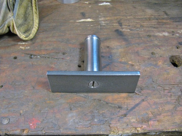
A bit of scrap steel from some failed project.

Turned it down and machined a recess in one end to accept a rare earth magnet.
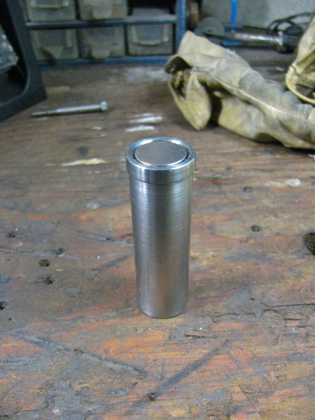
Fits in fine, held in firmly by magnetism and Locktite.
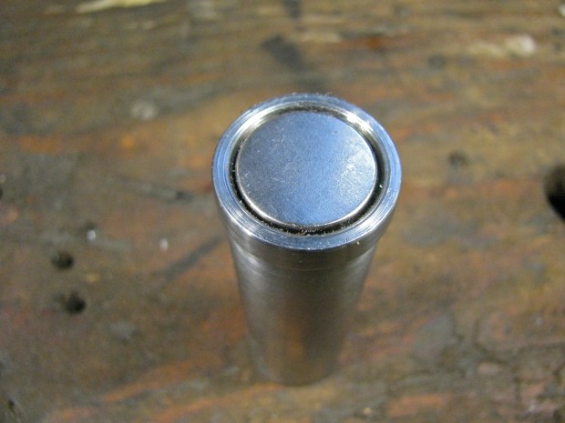
The magnet face is recessed from the rim of the tool by a gnat’s crotchet.

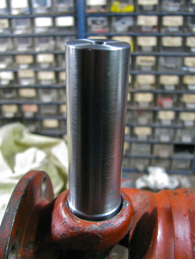
Here is my other propshaft, to be used for trial fitting. Big note here, ideally the circlip should be removed so that the tool can lie directly on bearing cup. But I reasoned that these circlips would be lying parallel to the bearing cups. Any dirt or damage to the circlips would screw things up.

Tool on the joint.
Angle finder on tool, held by magnets on side of angle finder. It looks like the angle finder is resting on flange, but it is not.

Angle finder on end of tool. I was not sure at this time which way would be better.

A bit of channel to provide a base to measure the propshaft angle.

Trying out the tool
Ok then, out to the van. First I had to install the re-balanced shaft (not the red one pictured above). I jacked up one side of van and supported on blocks. Wheels off the ground.

Small aside, I finally replaced the 1/2″ bolt used to hold the jack adapter onto the jack with a gated pin thing.

After the propshaft was installed (please note, I do insist on loosening the 3 bolts that go through the rubber mounts on the front diff. when I am installing/removing the shaft) I took the van off the blocks, released the parking brake and chocks, then crawled under to have a go at measuring angles. First I moved the van back and forth so that a bearing cup on the U-joint yoke that is attached to the flange was pointing directly down. I gave it a bit of a scrub then attached the tool.

See how the angle finder is a little askew on the shaft of the tool? This affects the angle measurement. It was hard to get the angle finder aligned true to the shaft when I was scrooched up under the van. Would have been much easier if the van was on a lift. But I persisted, went on to measure the propshaft angle.

And see how I do not have the angle finder aligned along the channel? It is askew too, and this affect the readinghh. And then on to the front diff. end of shaft.
Repeated the procedure a few times.

A bit better alignment on channel.
Again on the front.

And on the rear.

But I was not happy with the procedure, I was not sure of confident of the accuracy of the readings.
V-block modification and engine carrier adjustment
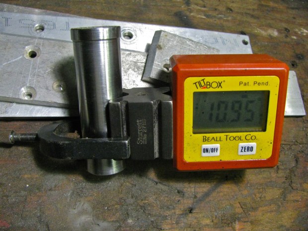
I tried a nice little Starrett V-block on the tool. I thought it might help me to keep the angle finder aligned along the long axis of the tool.
I was running out of afternoon and I wanted to try something more. I knew from previous measuring that the transmission flange pointed down more than the front diff flange. I wanted to reduce that angle, but I also new that there really is no easy way to do that. The transmission mounts towards the front of the transmission are really awkward to get at and fiddle with (especially when you don’t have a lift), so that leaves the engine mounts at the rear. But the arrangement/relative placements of the mounts means that it takes a fair bit of movement at the engine mount to effect a little movement at the transmission flange. Perhaps these data from R. Jones illustrates this (front diff. data included).
“4) I measured the distance between the flanges and the
mounting points, tranny and front diff, and worked the ratios.
Using washers, here’s what one can do:
a) raise front mount, front diff, lower flange.
1 unit raising gets 0.83 units lowering the flange.
b) raise rear mounts, front diff, raise flange.
1 unit raising gets 1.2 units at the flange.
This is the wrong way however.
c) lower tranny at front mounts, lowering flange.
1 unit at mount gets 1.25 units at flange.
Again, this is the wrong direction.
d) lower engine at carrier attachment to frame,
raise flange. 1 unit at engine gets 0.25 units
at flange. Hardly worth it.”
I wanted to try “d”. So I supported the engine carrier (“moustache bar”) with a jack and removed the 2 bolts, each side, that hold the bar to the van frame. I had no time to record flange angles vs. amount of lowering of rear carrier, and I decided to try 5/16″ as the distance lowered. Handy number, I had some 5/16″ aluminum plate scrap on hand. On the top side of the flange on the van body that the carrier mounts to there is a steel backing plate. I used that plate to lay out the bolts holes in the aluminum spacer.

Holes drilled.
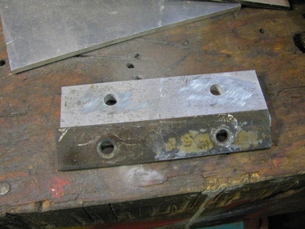
And spacer inserted. I used longer bolts. Damn mudflap mounting strut interfered.

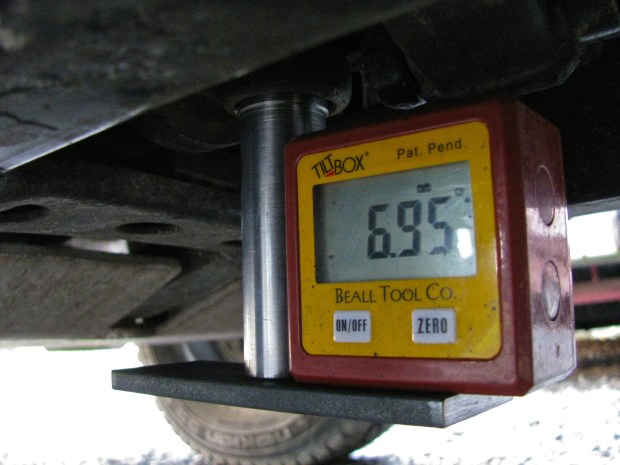
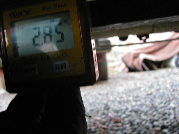
Maybe you can tell, the light was fading fast. I got back under and measured angles, using the V-block innovation.
Transmission flange angle.

Front diff. flange angle.

By now it was dark and I was cold. I left things as they as far as I got to: rear engine mount dropped by 5/16″.
It now occurs to me that I have not mentioned another little thing I did (a year ago) to resolve flange angle difference – I removed the topmost metal washers of the two rearmost mounts of the front diff. This did drop the flange of the front diff. a bit – I reasoned back then, that if I could not reduce the flange angle of the transmission the I would increase the flange angle of the front diff. I hoped that matching the flange angles did more to reduce vibrations than trying to get both flange angles below 4 degrees. I’ll clear this up at the end, I know this story is getting very muddy right now.
Road test
Okee dokee, I drove the van for the next couple of days. Felt pretty smooth, my 50-60 kph minor vibe has gone. I do have the very, very slightest vibration especially when accelerating, at around 40-45 kph. But I noticed this when the propshaft was removed so I am discounting that it has anything to do with the shaft.
I was pretty happy with this. I’d say that the re-balanced shaft is sweet.
Further modification to the tool
But I still wanted to measure the flange angles with somewhat more confidence. I cut a chunk of 1.5″ X 0.25″ hot rolled flat stock, drilled a hole, and screwed it (1/4 “- 20) to the end of the little tool. I checked it for square, was good. Now I had a better reference surface to place the angle finder against, and I could line up the long axis of the plate with the propshaft.
Here it is on the transmission end of the shaft. It is much easier now to use the angle finder to determine that the tool is pointing straight down, and the plate can be lined up fore and aft with the propshaft. Those two things are important in measuring the true angle of the flange. Remember, the tool is on the bearing cup in the flange yoke of the U-joint. That means it projects the angle that the transmission flange is making with respect to the propshaft.

One way of doing it. The angle finder was inline with the bottom plate of the tool. This was not a recorded measurement, I had not adjusted propshaft so that tool is pointing straight down.

I found that having the angle finder in this position was the best. The magnets in the angle finder held it to the vertical shaft, but still allowed it to be aligned to the bottom plate.
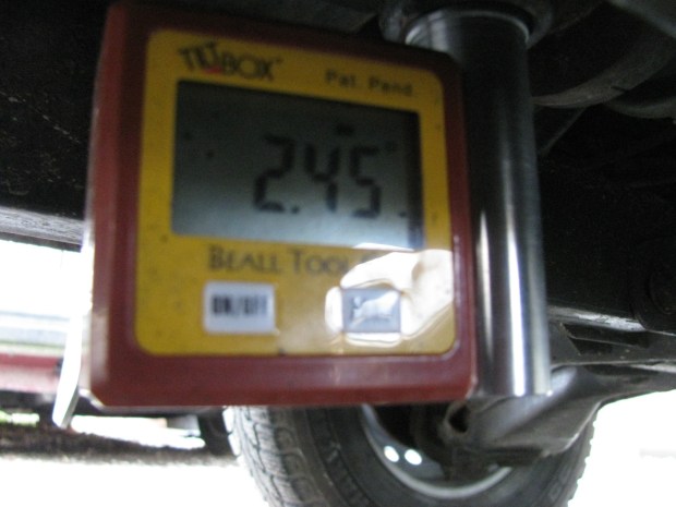
A another measurement (using the channel) of the propshaft angle.
And a good measurement of the front diff flange angle.

Results
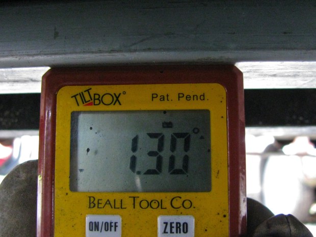
Ok, I was getting more consistent measurements, now to look at some of the data. Remember, we are measuring relative angles here, not absolute angles. For example, the propshaft could be pointing down towards the front at 1.30 degrees, or at 2.85 degrees depending (apart from measuring errors) on the level of the van (ie just exactly where it was parked in my driveway). The sketch below summarizes my results. The top cartoon represents the situation right after I installed the propshaft. Let’s go over it, bit by bit.
The transmission flange (and the transmission and engine) is pointing down towards the front of the van at 5.5o degrees. The propshaft is also pointing down in the same direction, but only at 1.30 degrees. If we subtract the propshaft angle from the transmission flange angle we will find that U-joint operating angle, and it is 4.20 degrees. Remember: if the angles are in the same direction then subtract the smaller angle from the larger angle to find the joint operating angle.
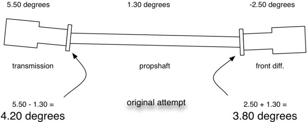
At the other end the front diff. is pointing down towards the rear of the vehicle, in the opposite direction of the propshaft angle. I added a negative sign to that measurement to remind me of its different direction. So in this situation the absolute value of the front diff. measured angle, -2.50 degrees, is added to the propshaft angle of 1.30 degrees. Result is a 3.80 degree joint operating angle. Remember: if the angles are in opposite directions then add the absolute values of the two angles to find the joint operating angle.
As clumsy as those two paragraphs are, I hope you get the idea of how the operating angles are arrived at. Of course with an electronic angle finder I could have zeroed on the propshaft angle and read the working angles directly. But I thought it would be clearer to me and to you if I did it explicitly.
Now the measurements after I installed the 5/16″ (8 mm) shim back at the engine carrier.
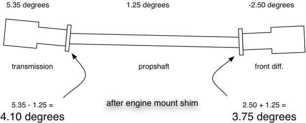
And finally, the same set up but this time more accurately measured (bottom plate added to my home-made tool).

I am fairly confident in this last measurement. Even if it is not perfect, I am sure the two flange angles are within 0.2 degrees of each other, though I do wish that the operating angles were less.
Compound angles
At the beginning of this post I said I was going to discuss compound angles, so here we go. The above sketches show angles in a vertical plane, but you can imagine that the same thing could be going on if you could look down from above. The transmission and front diff. could be laterally mis-aligned. What is interesting, is the combined effect of both lateral and vertical misalignment. The Aquadrive document I linked to previously has some good information on compound angles.
The accurate formula for calculating the compound angle is:

Lovely stuff eh? Shall we do an example? (and please God, let me do the math correctly).
Let’s say we have a vertical flange angle (ie the kind we have been measuring ) of 4.1 degrees. And let’s say the lateral angle is 1.0 degrees. First step is to find the tangents of those angles.
tan 4.1 = 0.0716808913
tan 1.0 = 0.0174550649
we square both of these numbers and add them together:
(0.0716808913)^2 + (0.0174550649)^2
= 0.0051381502 + 3.0467929066e-4
= 0.0054428295
then we take the square root of that number and we get:
0.0737755345
now we take the arctan (inverse tangent) of that number to find the answer, our compound angle:
compound angle = arctan (0.0737755345)
compound angle = 4.22 degrees
(Another example – 4 degree vertical angle and a 2 degree lateral angle, then the effective compound angle would be 4.47 degrees)
Not much of a difference, 4.22 degree compound angle compared to 4.10 degree vertical angle. So should we worry about lateral misalignment? Well, in the stock set up there is some room to laterally adjust both the transmission and the front diff. The old trick of leaving the front diff. mount bolts a little loose after installing the propshaft, then driving the van for a few miles before tightening those bolts, probably serves to reduce or eliminate lateral mis-alignment. But with vans that have non-stock engines/engine carriers installed, then there is a very good chance of having the engine and transmission laterally askew enough for that trick not to be enough.
Conclusions:
- no matter what you read or hear, in the vanagon syncro the propshaft operating angles should be 4 degrees or less (but not zero degrees). Ideally they should be less than 3 degrees. Unfortunately there is no easy way to adjust the front diff and transmission vertical flange angles to achieve this. On vans with engine conversions and modified engine carriers, careful attention MUST be paid to the transmission angle.
- U-joint operating angles should be the same or within 0.2 degrees of each other.
- measuring the angles can be done fairly accurately with home-made tools. A smart phone with an inclinometer app could be used instead of my little electronic angle finder. But some sort of adapter between the joint and the phone must be used to ensure accurate and consistent readings.
- lateral misalignment of the transmission and resulting compound angles are very important to check and deal with if a non-stock engine has been installed. Remember that the angles combine and result in an effective angle greater than any one of the individual angles.
- Your man on Vancouver Island for propshaft balancing is Royce at Island Torque Converter & Driveshaft. Phone # 250 388 4248
Vanagon syncro – front spring swap and radius arm bushing replacement
Posted by albell in syncro specific repairs, vanagon, vanagon mods on January 6, 2013
The other thing I did recently was swap in a pair of front springs from my old ’82 westy into the front of my ’86 syncro. You know that that suspension set up is different between the 2wd and syncro vanagons, the syncro has a spring perch on the shock absorber and uses (generally) shorter springs than the 2wd vans. I compared the spring lengths of the ’82 diesel westy and my ’86 syncro in this blog post, and in this post. This particular 2wd spring is about 20 mm longer than the syncro spring, but the wire diameter (approx 16.6 mm) and number of turns (8) are the same. The spring rate, if I have identified the 2wd spring correctly, is according to the IG16 wiki 80 N/mm. It is the same spring rate as the syncro springs I have. It seems only one spring type was installed in North American market syncro tintops and westies.
I’ve not been pleased with the amount of “springing” in the van. With the westy conversion it must be a bit heavier than it was as a tintop, and I find that the van scrapes the spare tire clamshell on the ground when I’m negotiating ditches, trenches etc on logging roads. Friend Simon would add that my excessive bulk is not helping things. The distance between the front fender lip and the wheel centre was about 18.25″. I would like it to be at least 19″, but not more than 19.5″. At the back it is trivial to add some shims to raise things, and I did do that (rear measurement 19″). That shimming made the front end look even lower.
I’m not ready to dive into the hyperbole ridden and expensive world of aftermarket springs and shocks, and one must consider springs and shocks together. Increasing the spring rate does require increasing the dampening abilities of the shock.
Originally thought that I would add a shim to the top of the spring, but then I decided to give the spring swap a go. I did not know whether the “no compressor spring removal” technique would work with longer springs so I bought a rather cheap spring compressor from Princess Auto. Spring compressors give me the willies, I feel like I am on a bomb disposal mission when I use them.
Upper A-arm disconnected from upper ball joint, you’d think there is enough room to get the compressors in.

Nope, not enough compression with this set up.

Ditto here. The hex area at top of compressor does not allow you to get a grab on a higher coil, plus at the other end, the screws are too long and interfere with the axle shaft. I wasted about an hour mucking around with the compressors, I finally gave up. I could have cut the screws down, but I was of two minds about that. Was it worth wasting more time trying to get them to work or try and return them to the store?

So I went back to the no compressor method. Radius arm arm was removed, sway bar drop link disconnected, nut and rubber bushing removed from top of shock, and the lower control arm carefully lowered so that the spring and shock could be pulled out to the side and the spring removed. One thing though, I had installed a westy swivel seat base on the passenger side this summer. So I had to make a hole in the base to access the plug that, once removed, allows you to put insert a tool to guide the shock back up into the shock tower during re-install.

So, I got the passenger side spring installed (radius arm bushings on that side done too) on New Year’s day. With one spring installed, and before driving to settle things in, I got a 19.5″ measurement from hub centre to fender lip. I like that look, it is as high as I want to, or should go. A couple of days later I got the other side done and the hub to fender height settled in at 19 1/8″. Driving the van felt a little different, I could tell the front was higher (yes, I really could detect the change), there was no difference in how the van dipped or raised over bumps. Mind you this was only driving over the lumpy roads in North Saanich, no logging road travel done yet.

Now some shameful pics of the dreadful state of my radius arm bushings…
New bushings and radius arm. Note the shiny spacer I made over a year ago.

Old and new.

“By Timothy, what a difference”

“Shocking!”

Conclusions?
Well I think the spring swap was worth the effort but I will add a teeny tiny little spacer (about 1/4″ thick) to bring it up to 19.5″ hub to fender lip measurement. As to the radius arm bushings, I don’t think any further comments are needed.
Vanagon – my auxiliary battery wiring
Posted by albell in syncro, vanagon, vanagon mods on January 6, 2013
I only had a little time to do any Vanagon stuff over the break, a couple of things were dealt with, I’ll post it up over the next couple of days.
First up is my auxiliary battery install. It has been working fine for the last couple of years, but recently I have noticed (with the help of the Doc Wattson, blog post here) a couple of disturbing things. First one is, and I have not figured this out, is a peak amp reading of 20 – 30 Amps. I never see it happening, even with mucking around with stereo settings while I look at meter. And I don’t have a circuit in my aux. battery set up with a fuse larger than 20 A. I do suspect the stereo amplifier, but it must be a very brief transient spike in current draw.
The second thing is a chronically undercharged aux battery. I suspected, and suspicions confirmed by the Doc Wattson, that the Blue Seas ACR (a now discontinued model, CL series BatteryLink, p/n 7600) I use to switch between the main/starting battery and the aux battery was not combining the batteries when it should have been. The ACR ( automatic charging relay) does have indicator lights on it, but the unit lives under the driver’s seat.
The ACR has provision for wiring in a remote located LED that lights up when the ACR combines both batteries. So I set about adding that and at the same time I would go over connections and ACR settings. I suppose a picture to give you the lay of the land would be a good idea. I admit, it is a bit of a dog’s breakfast. Working around clockwise the stereo amp is on upper left (old Alphasonik that came with van), then auxiliary fuse panel, to the right and up is the Doc Wattson meter, below that is the 31 A/hr AGM auxiliary battery, Schumacher trickle charger, then finally the Blue Seas ACR.

Yeah, clear as mud. Fine then, I’ll make a quick sketch.

Edit: link to how I connected to main fuse panel S3 circuit from aux. fuse panel.
Under the cover of the auxiliary fuse panel. Its is from an early 2000’s Golf/New Beetle and was installed right by the battery. Useful little thing, I’ve had this one for about 11 years (used it on my old ’82 westy).

Ok, back to the ACR trouble shooting. I ran a pair of wires up to the dash, and mounted a blue LED indicator light in a rather temporary way under the lip of the dash. The light is from Princess Auto, made to fit a 1/2″ hole and has resistor built in, much easier to buy than to fiddle around making one up – ha, I must be getting old. Disregard switch and knob to the left of the light, has nothing to do with this job.

Testing connections, oh, brighter than I imagined. Looks like it is going to provide some mood lighting.

Ok, so I have the indicator light installed which will let me know when the ACR has combined the starting and the auxiliary batteries, and I have gone over wiring connections and ACR settings. First time I drove the van all went well, the LED came on after about a minute (this is as it should). The second time I drove the van the light did not come on, the ACR did not combine the batteries. What is going on? I moved the driver’s seat and looked at the ACR – well blow me down – the over voltage light was on.
I should explain, the ACR has 2 user adjustable settings. One is the voltage at which the batteries combine or un-combine. I have it set at 12.5 V and that means when the ACR senses that the voltage on the main (starting) battery drops below 12.5 V it will un-combine the batteries. And when the voltage measured on the main battery is above 12.5 V, than the batteries are combined (there is a time delay built in to weed out voltage spikes).
The second user adjustable parameter is the over voltage setting. The manual states:
“The OVERVOLTAGE potentiometer is used to adjust the voltage at which the CL-Series BatteryLinkTM ACR switch opens in response to high voltage. This is a protection feature when one battery needs to be charged at a lower voltage than the other. It also protects the second battery bank in the event of an overvoltage condition produced by the alternator.”
The van is still running and I glance over at the Doc Wattson meter and notice that it reads 14.94 V. So that’s it, the ACR has un-combined the batteries because of a too-high alternator voltage. I had the over voltage set to 14.85 V, and that seemed fine as I had adjusted my alternator to 14.5 V (yes, I have an adjustable reg. on the alternator), but now the alternator was putting out 14.94 V. It is strange, I didn’t see that high a voltage any time before.
I re-adjusted the voltage reg back down to 14.5, and the over voltage light went off and the batteries were combined.
Edit: Dennis H. advised me to re-adjust the voltage reg down to a max of 14.2 V. I think I will follow his advice.
So was this the ironic reason my aux battery was being undercharged – alternator voltage too high? I have to admit that I’m not 100% confident in the adjustable volt reg. I put in the alternator. I had one flake out on me on my old ’82, and now this one might be showing signs of “wear”
Finally (thank god, what a long winded and dull post), I still have that old Halon fire extinguisher I had in the ’82.

