Archive for August, 2010
Vanagon camperisation, part 3
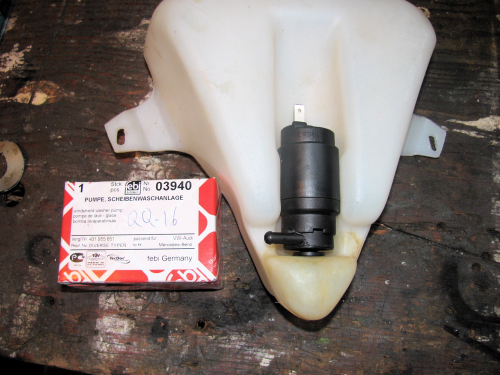
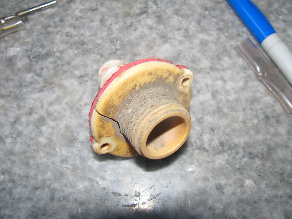
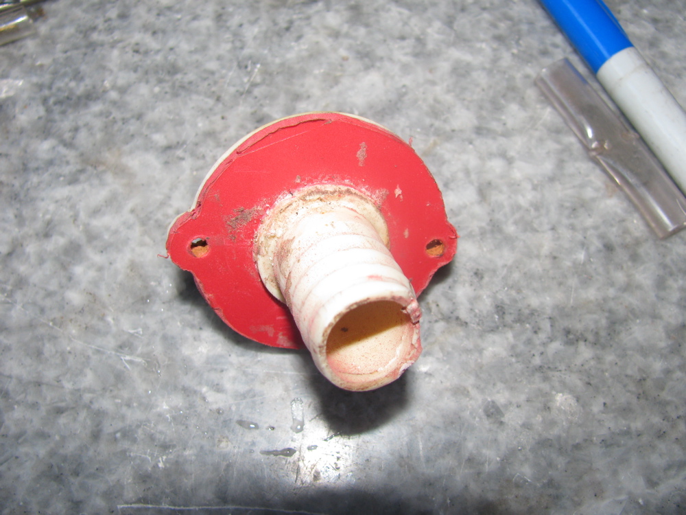
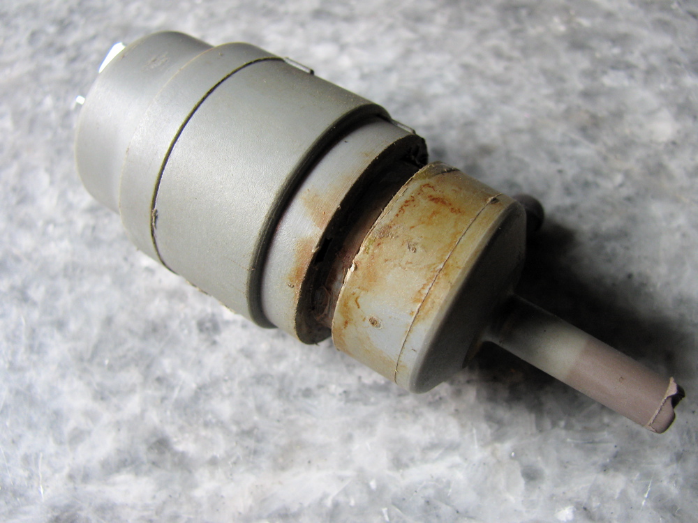
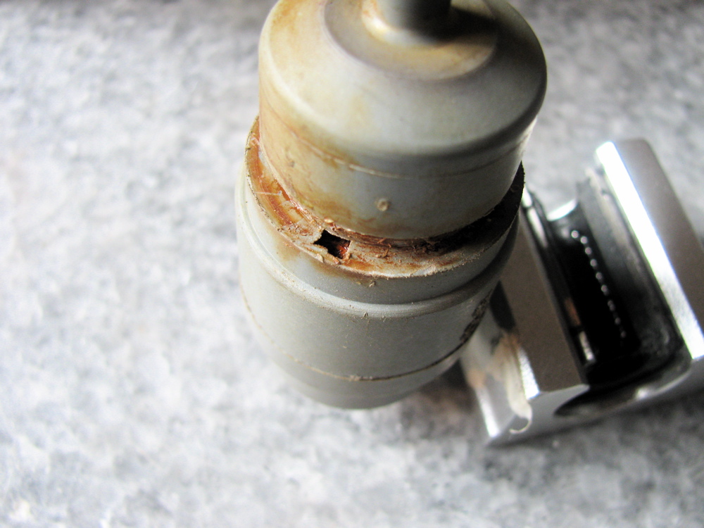
Not much progress in the last couple of days. A new rear windscreen washer pump was bought from dealer (best price, 20 bucks, had the option of $120 original from dealer, or a rather suspicious “trico” brand one from local parts supplier). I removed the old sink drain bulkhead fitting, you can see how I repaired it years ago with some red plastic. I looked for a stainless fitting to replace it with, but could not find one.
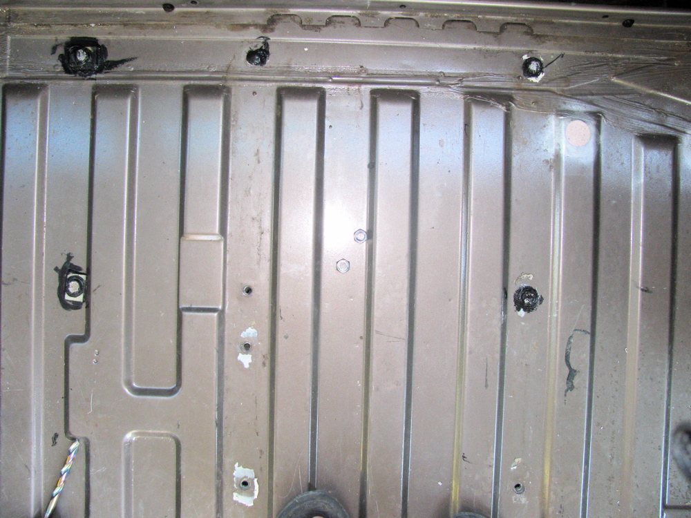
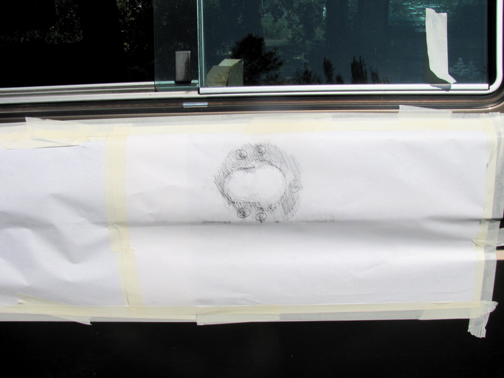
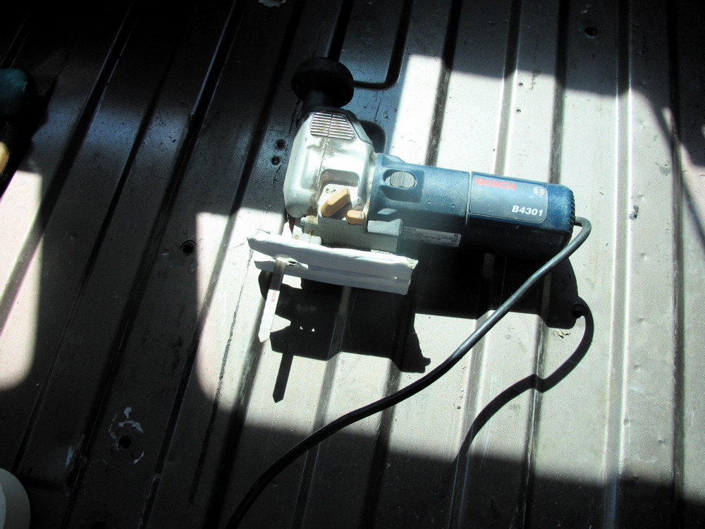
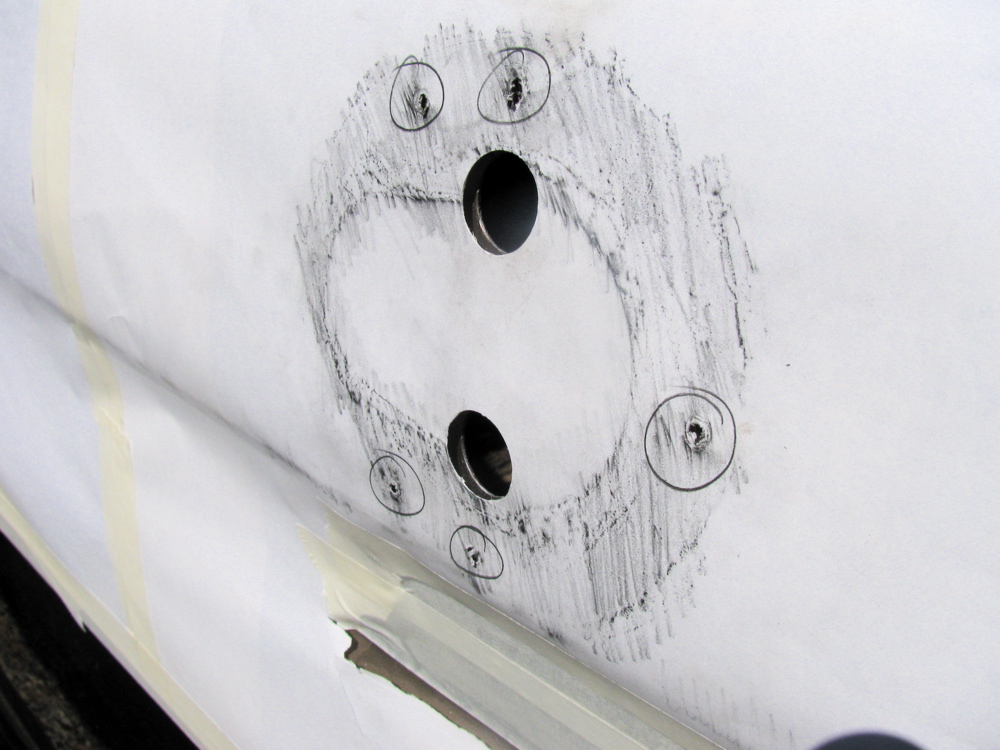
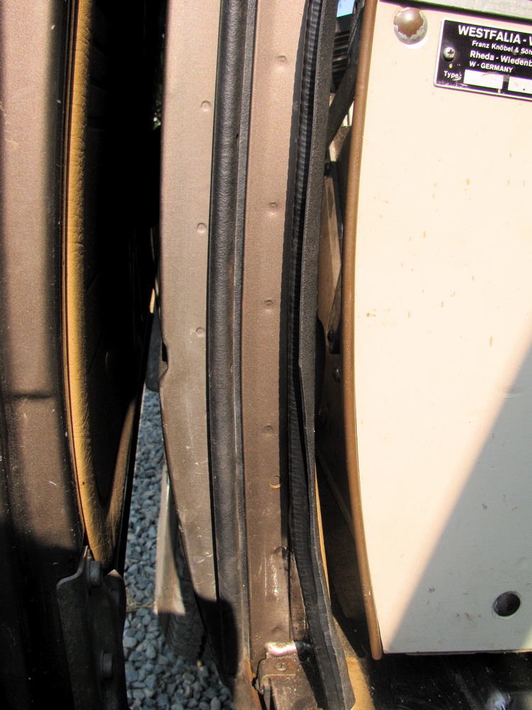
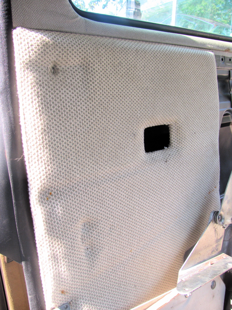
Also, I pulled all the cabinets and drilled holes for the rear most 2 attachment points for propane tank. The forward 2 points use the existing welded nuts for the seat tracks, but new ones had to be drilled, metal “washers” installed and the bolt held in place by nylock nut underneath. Silicon caulk applied liberally, and all 4 bolts stainless steel. The fridge vent hole was cut. I used paper to make a “rubbing” of the shape and location of hole on my Westy, and taped the paper to the syncro and first drilled the screw holes, then used punches to make the “ear” shaped curves and finally a saw for the rest. I taped the base of the saw to insure no scratches on van’s side.
I also put in a second battery and automatic charge relay. The install is preliminary, nowhere near picture worthy yet.
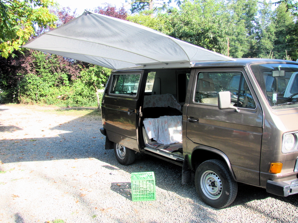
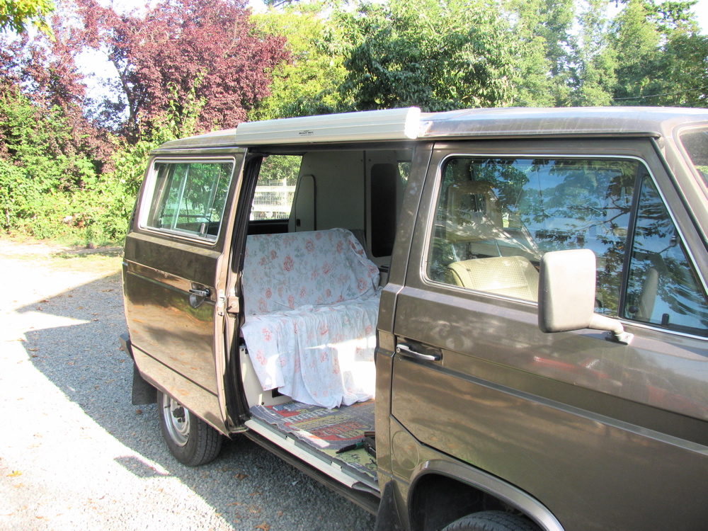
Finally, today I installed my “Shady Boy” awning. I really like this awning, lightweight, simple, and it works. Picture show it deployed without guy lines or down draught poles.


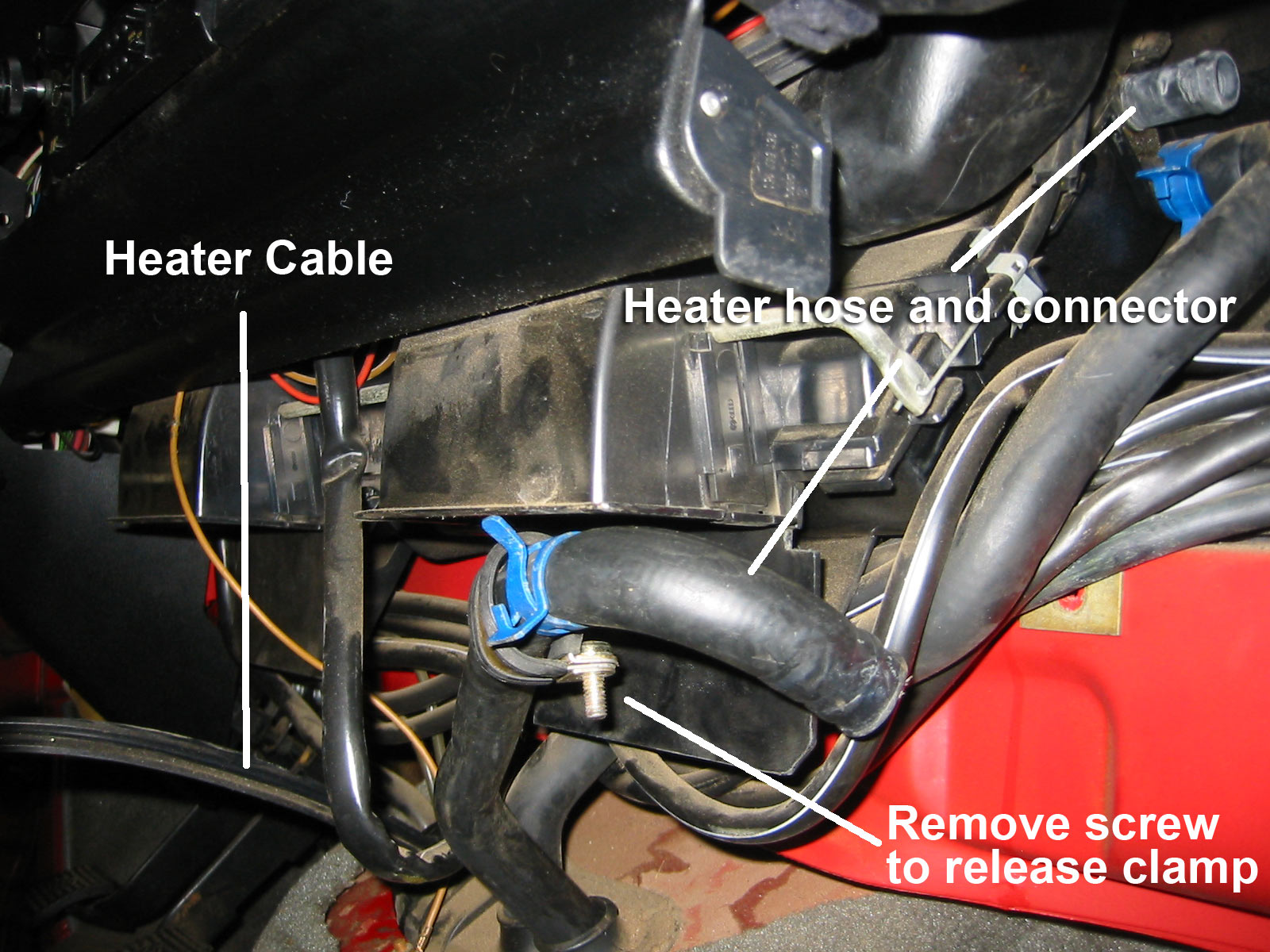
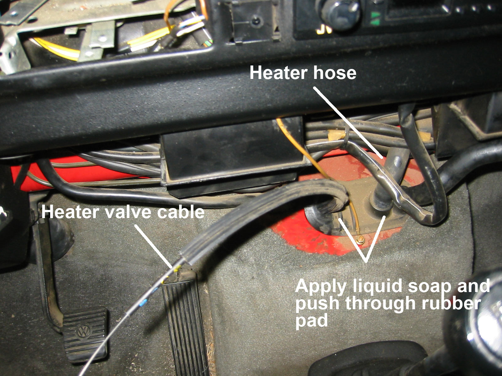
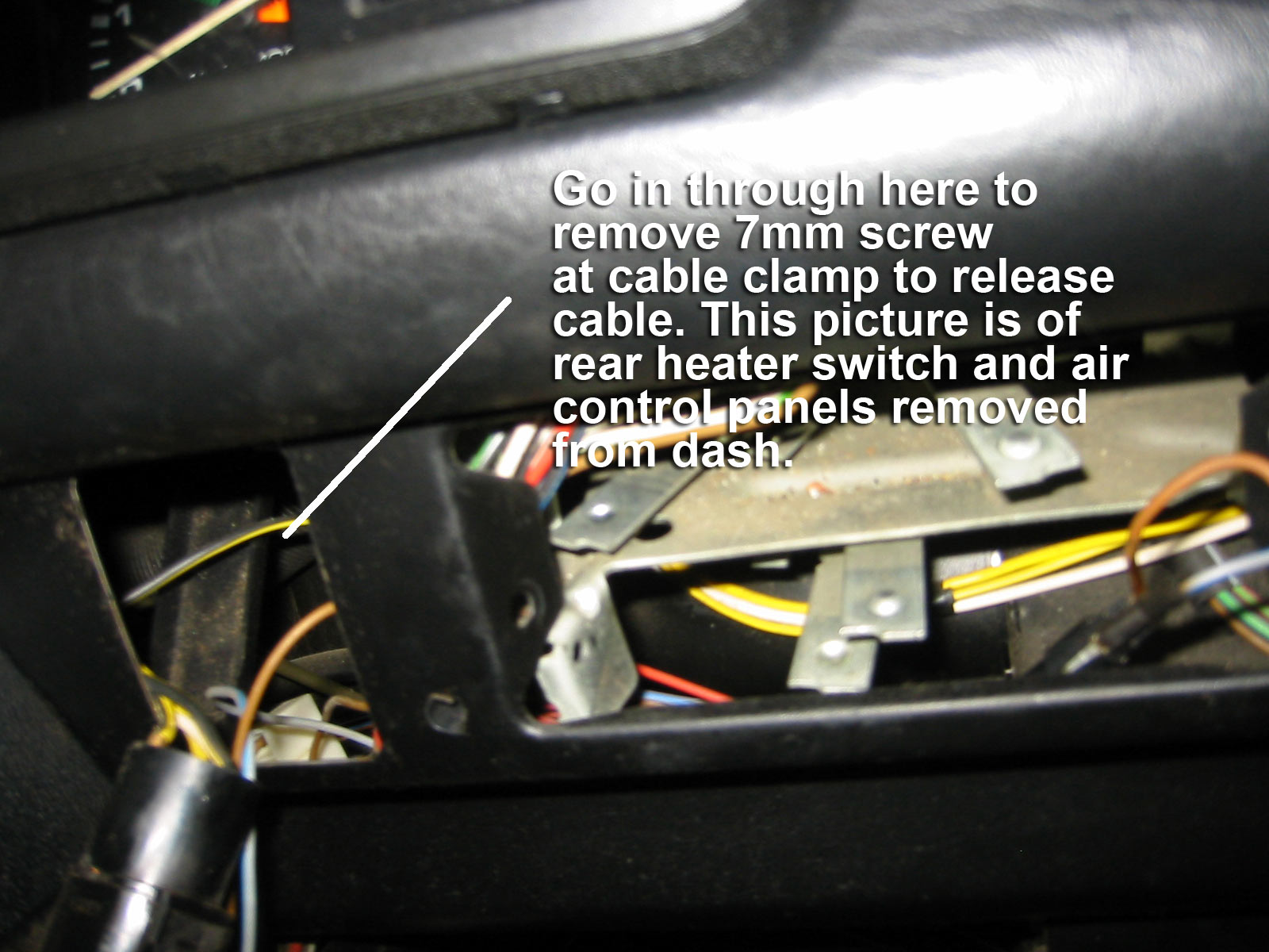
Vanagon heater valve replacement
Posted by albell in vanagon, vanagon mods on August 19, 2010
Jim’s annotated photos.
’83 Vanagon diesel dipstick mod.
Posted by albell in vanagon, vanagon mods on August 19, 2010
Jim writes:
This might be of interest to anyone wanting to use an 82 block with a later Model vanagon, or for anyone wanting to get away from the stick-in-the filler tube setup.
A few weeks back I wrote that I had carefully studied and measured the dipstick tube on my vanagon-specific NA diesel and was trying to make another one out of brake line for the 82 vanagon-specific block I was building.
What makes the blocks specific to the years is the treatment of the “dipstick” hole in the side of the block. With the 82 block, the hole is plugged with an aluminum piece, and the dipstick assembly is part of the oil filler tube.
I was going to use the dipstick tube out of the original 83 engine after knocking the aluminum plug out of the 82, but upon careful inspection, it isn’t that simple.
The machining in both holes is different. The 83 has a larger top part—the holes are step- drilled so that the bulge in the dipstick tube will seat at the step, assuring that the marks on the dipstick itself are the correct distance from the bottom of the pan and thereforeread accurately.
The bulge in the dipstick tube on the 83 will not even fit into the 82 hole at all without grinding it down, which would thin the tube walls, making it weak and ruining for further use in an 83.
So here’s what I did:
Start with a 7.5 mm steel brake line 36 inches long, and while you’re buying it get a brass compression fitting that just barely fits over it. They make one that’s perfect, you just have to try a couple of sizes to find it.
Cut off the flanges on both ends of the tube. slide the compression fitting over one end and touch a grinder with the fitting so that it grinds concentrically as the fitting is spinning on the tube. It doesn’t take much, you want a nice fit so be careful
Push the fitting up from what will be the bottom of the tube so that the bottom of the ferrule is 30mm (7 and 5/8 inches) from the bottom. This has to be exact. Now mark the top and bottom position of the fitting and use a small file to clean the metal of the tube where it will sit. Now solder it in place.
Slip a coil spring type pipe bender over the tube and bend it to shape by hand (I think I’ve already posted a picture of the proper bend photographed against a 1 inch grid for reference). The curve should be smooth, but it doesn’t have to be particularly faithful to the original for the setup to work. What DOES have to be accurate is the distance of the compression fitting from the bottom of the tube, and the length of the tube overall.
Go to a junkyard and get any VW gas or diesel dipstick where the orange plastic piece snaps over the end of the tube. Unsnap it and throw away the tube, you are going to put the plastic piece on the end of the tube after bending the pipe, and cut the tube several times until the dipstick (dealer item if you don’t have one) protrudes from the end of the tube exactly two millimeters.
Once done, drop this into the dipstick hole in your block and seal with black permatex. Behind the alternator, under the nut, drill and trim a hadware store angle bracket to fit under the nut. I bent the top, flat part of this to conform to the roundness of the tube and secured the tube to the bracket with a hose clamp.
After putting 3.5 quarts of oil in the car, the dipstick shows the level exactly halfway between the marks.

adding middle seat rails to a Westy
Posted by albell in vanagon, vanagon mods on August 19, 2010
Jim writes:
How to install middle seat rails in a westy
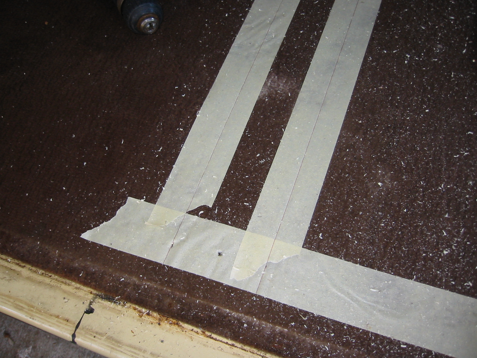
You’ll need a way to get under the car, a circular saw, the usual hand tools, a set of seat tracks and the fasteners for those tracks, a marker, a tape measure and a straight edge and some 2″ wide painter’s tape. The tape will allow you to mark accurately for the cuts, and will help the carpet cut cleanly. You will need a very long 3/16th (approximately, it just has to fit through the center of a 13mm bolt hole–that’s a head size of 13mm, not shaft diameter) drill bit, about a foot long I believe. You will use the bit to drill up through the bolt holes in the bottom of the van to locate the center of the pieces you are going to remove. It’s tight up against body crossrails, and the drill body will interfere with these if you don’t have a really long bit.
When the instructions refer to bolt holes in the floor, realize that every vanagon ever made, as far as I know, has the bolts for this welded into the metal of the floor. The trick is to remove two sections of wood that cover the holes in such a way that when the sliding seat trays are dropped in, their holes align exactly with the fastener holes. It isn’t difficult if you can mark and measure carefully.
First pull out the fridge unit so you have access to the whole width of the floor board. Take off the front (door side) trim.
Go underneath with the long drill and locate the fitting welded into the floor where the floor track will be. This will be obvious as there will be two rows of them across the car in about the middle of the rear area. Once you have drilled up through the two fasteners near the door, measure over the width of the floorboards and then go below to locate the corresponding pair. You don’t want to go all the way to the driver’s wall because there’s no point in removing the plugs. You are not going to use them because the seat rail won’t reach them.Start at the ones just inside the door and drill up through the floorboard. You are drilling through a plastic plug. After you get the floorboard strips removed, you can remove all of the plastic plugs from the top with with a phillips head screwdriver. But, until you can remove the wood flooring, you must very carefully mark where you are going to cut, and for now must be content with drilling as small a hole through them as is feasible. You don’t want to break the drill bit off, but you don’t want to big a drill either. Just something large enough to find the hole in the carpet to use as a point of measurement. If you drill too large a hole in the plastic plug, you will just spin the plastic plug and it will not want to come out. You will also have drilled out the molded phillips head pattern in the top. So, use as small a drill as you can.
Lay down a strip of tape over all four holes, running fore and aft, each about ten inches long. Punch down over the hole to locate it in the tape. This will create your four reference points. Now run masking tape across the floor of the van between the marks. Now measure the width of the seat rail tray where it drops into the slot (not at the edges of the flanges). Look at the end and you will see this for yourself. The flanges down both edges of each piece are meant to cover the edge of the channel and embed in the carpet.
Measure this distance, divide it by two, and mark this distance out from your reference holes. Connect the marks across the width of the floor with a line from the straight edge. The material between these lines is what you will saw away.
Use the open area between the floorboard and the wall to set the depth of the circular saw to saw through the bottom of the wood without touching the metal and ruining the blade. It can be done. If you are worried about this, leave yourself a 64th or so and get the last with a knife blade. Lift the strips out and you will see all the plastic plugs that can now be removed.
Simply screw in all the track pieces–they will only go in one way–and replace the stove and fridge. Slide the seat in for reference before you do final tightening on the rails.

Replacing power window motor
Jim writes:
Replacing power window motors and regulators in a Vanagon
Once you’ve done this job once or twice, you can get in an out in less than an hour. It’s really not all that hard a job, just that when you don’t know how to twist the motor on the cables to get the assembly to slip out, you end up doing a lot of unneccessary tugging and pulling and scraping. The longer you keep a vanagon, the faster you get at this.
Instead of using a clamp to hold the window up, you might try cutting a couple of small wooden wedges to jam the window to the rubber so it won’t drop.
Here’s the sequence of events, best I can remember, The only tools you’ll need besides the wedges are a phillips head screwdriver, a small knife to pry with, a 10mm socket and a 10mm combination wrench. Maybe something else, but basically that’s it. When you get the motor out, you’ll need a good sized soldering iron to remove the short harness and connectors from the old motor and put them on the new motor. Make a sketch of how the wires connect to the weird little terminals on the motor or the window might work in reverse. Ask me how I know.
First, take the small bladed knife and pop the end covers out of the pull handle. You’ll see what I mean if you look closely. Pry out the molded-in end covers, working on the “inside” end closer to the center of the handle, as the outside edge (adjacent to the upholstered panel) is a plastic hinge. When pried open, the screws are revealed. Remove them and keep them organized, they are of two different sizes.
Next go after the door latch plate. Pull up the handle and pry out the plastic insert from the little slot at the front. This will reveal a phillips head screw, remove this and lay the parts aside.
Next comes the vent in the lower rear corner of the panel. There are two screws facing you when you look at the panel.
Now the panel will pop off with a tape-covered screwdriver. Try to find a fastener and pry near it rather than in the middle between two fasteners. When you can get your hand in, continue around until the panel is loose.
Carefully remove the plastic wind seal, you will either need to reattach or replace it with contact cement or tape.
If you have speakers, make a note of how they are connected and disconnect them.
Unplug the window switch from the main harness and the motor. Cut any cable ties you find fastening the motor.
The window needs to be all the way up to do the next steps easily. Now is the time to take a look as to how they will be accomplished.
The window glass sits in a metal rail that is bolted to a mechanism that is part of the window raiser. This part is the same for crank-up or electric windows. The trouble is that you will need to get to the two 10mm bolts that fasten the window to the raiser. If the window is not all the way up, this may be your biggest challenge but since mine isn’t apart, I cant’ describe the situtation further. But this is what you have to do next.
Following that, raise the now-loose window to the top and jam or clamp it to keep it out of the way. You will see a vertical galvanized metal track that the raiser slides in. If I recall correctly, a bolt in the side near the top and a bolt in the bottom of the door–yes, you have to look underneath the edge of the door–hold this track in. Remove these, don’t confuse the bolts with the two shorter ones that hold the window to the raiser.
The vertical track is loose, but it is connected to the motor by two cables in housings. If the housings are broken, bent or rusted, go ahead and order them too right now.
Now all that needs to be done is to remove the three 10mm bolts that hold the motor in.
Once that is done, the motor can be twisted with one hand about 90 degrees to make the cables align together as the other hand moves the vertical track, bottom first, toward the motor.
If you’ve done your twisting right, the whole thing will slide out the motor hole. When the motor is released, the whole thing will spring back to its arrangement in the car.
Two 13mm bolts hold the motor on to the mechanism. As I said, you may have to transfer a plastic mounting collar and a short piece of harness to the new motor, but other than that, it all twists up and slides right back in the way it came out.
Replacing transmission driveshaft seals
Posted by albell in syncro specific repairs, vanagon on August 19, 2010
Jim writes:
Tools: nothing special in a modestly-equipped shop. Assumes you have a small cheap inertial puller set.
Do one side and then the other. In both cases:
1. Jack up the first side, chock the other. release the emergency brake and then put in neutral. You’ll need to lock up either the wheel and other times turn it (to remove and tighten the CV joint bolts) or the flange itself (for circlip removal/refitting) at various stages of this procedure.
2. remove the allen-head bolts holding the inner CV joint to the transmission flange. Clean out first with a small pick, then tap in allen wrench with a small hammer to ensure seating in the fastener. Otherwise, you risk rounding out a bolt.
3. Drop and bag the CV joint for cleanliness. Have some good moly greasy on hand if it needs repacking.
4. You’re looking at the flange. Talk a hammer and a sharp tool and drive it into the plastic plug in the center of the flange and pry out.
5. Remove the C-clip with two screwdrivers, better a screwdriver and a hook tool like a spark plug boot remover.
6. Use a 3-jaw puller to remove the flange.
7. Remove the two phillips screws that hold the plastic dirt shield to the transmission.
8. Clean everything you removed by soaking in gasoline, be sure you get the spring washer from inside the flange. Now you can see the seal in it’s aluminum housing.
9. Use a sharp-pointed tool east and west positions on the seal itself and punch holes.
10. Use the screw tool with the puller to screw into the holes you punched in the seal. There’s a big old ball bearing behind the seal, don’t worry about it. Keep turning the puller screw into the seal housing until the pressure of the screw point against the bearing rides the seal out of its home. When you tighten the puller screw with a wrench, you’re stopping the screw point against the bearing and riding the seal up the threads and out of its seat.
11. Oil up a new seal with transmission grease and tap home with a stick, dowel or rod about 1/2 inch diameter and about 8 inches long.
12. Tap flush with seal housing, keeping tapping constant while moving rod or dowel constantly around seal housing.
13. Remove soaking parts from gasoline and clean.
14. Refit plastic dust cover and screws and then refit flange. Protect with section of 2 x 4 and wail away with hammer until seated.
15. Refit spring washer cup out (center part the closest to you).
16. Refit clip ring with two medium flat screwdrivers. The first time you do this, it will take about ten minutes. The second time, about 30 seconds. There is a technique.
17. After fitting clip on axle stub, tap clip into place with small flat punch and hammer to make sure it is seated in the groove against the pressure of the spring washer.
18. Tap in new seal, smear joint with RTV adhesive.
19. Refit CV joint, packing with grease if necessary.
20. Repeat from step 1 for next side.
21. Drop shift rod by removing upper and lower 13mm bolts and nuts.
22. Remove transmission filler plug with 17mm internal socket.
23. Fill transmission per Bentley.
24. Replace filler plug.
25. Lube shift cup and shift bushing with moly grease, replace bad rubber as necessary.
26. Rehang rear shift assembly as reverse of removal in step 21.
27. It’s over


Some info from Jim Felder
Jim very kindly sent me a package of info files: dipstick tube replacement, heater valve replacement. middle seat rails in a westy, replace vanagon transmission seals, replacing power window motor, a sawhorse engine lift, 1990 sales brochure, and a 1990 window sticker (sales). I’ll post each as separate entries.

Viscous coupling rebuild
Posted by albell in syncro, syncro specific repairs, vanagon on August 16, 2010
In German, on this site http://www.2wd-goes-syncro.de/. Videos showing a VC being taken apart, cleaned, and new fluid added. Well worth a look.
Westy water tank install
Posted by albell in vanagon, vanagon mods on August 14, 2010
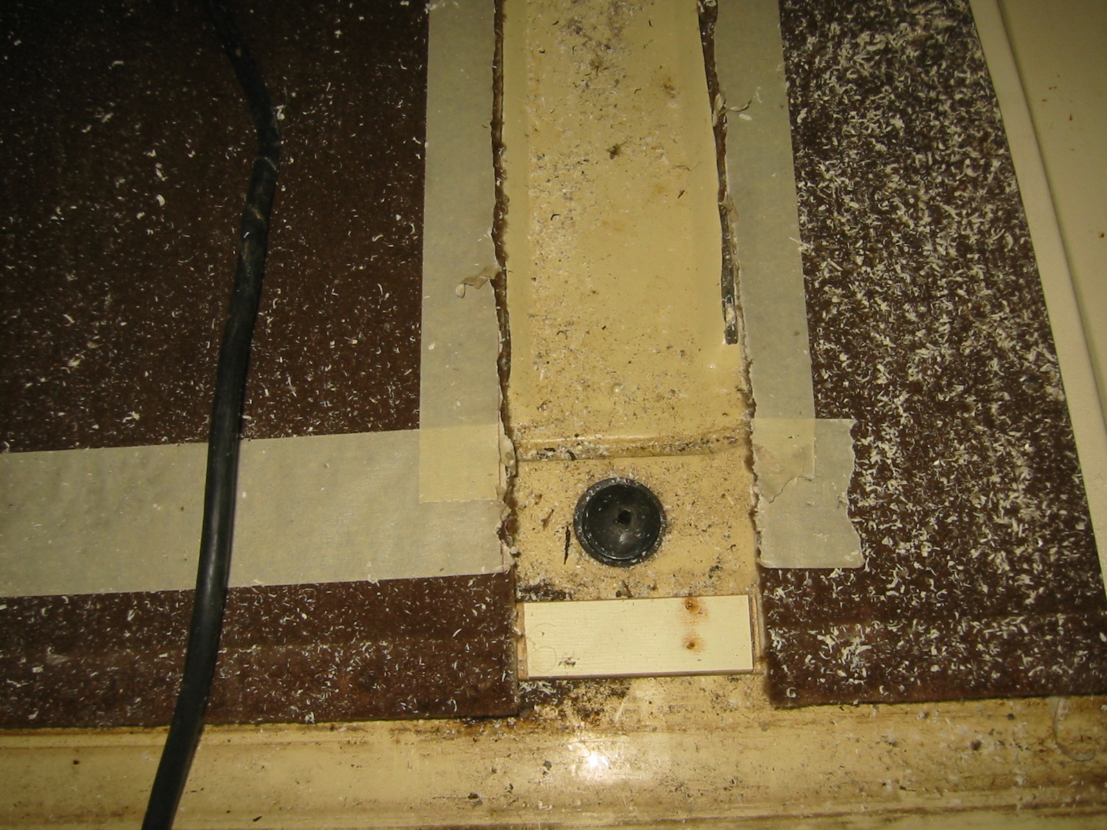
Hot day today, for Lower Vancouver Island, in the low 30’s. All I felt like doing after the overhead cabinet install was installing the fresh water tank. It sits against the angled back wall on the drivers side, and the drain pokes through hole in the floor. I measured where that hole is in my ’82 Westy , but crikey, there was a dimple on the Syncro’s floor right where the hole is supposed to be. And same thing further forward for the sink drain hole.
Water tank area:

And sink drain area:

Drilled on the dimple and went under van to realise hole was right where the old Webasto heater fuel pump is. The heater is not working, and wont be anytime soon, so I removed the pump.


Using that hole as pilot, I punched out bigger hole with Greenlee punch.

And then a bigger Greenlee punch.


So much nicer than using a hole saw. At this point I wondered why the heck was I working with the cabinet in place? Out it comes and a trial fit of tank.

I stuck some closed cell foam on bottom and back of tank for cushioning and maybe reduce any sweating. Westfalia jams in fibreglass insulation on the back, against the angled wall. Then caulk the opening (I had painted cut surface) and the tank goes into the cabinet and the cabinet lowered into place.


Tomorrow I’ll fit up some sort of gasket plate or just caulk the area on the underside of van where drain emerges.
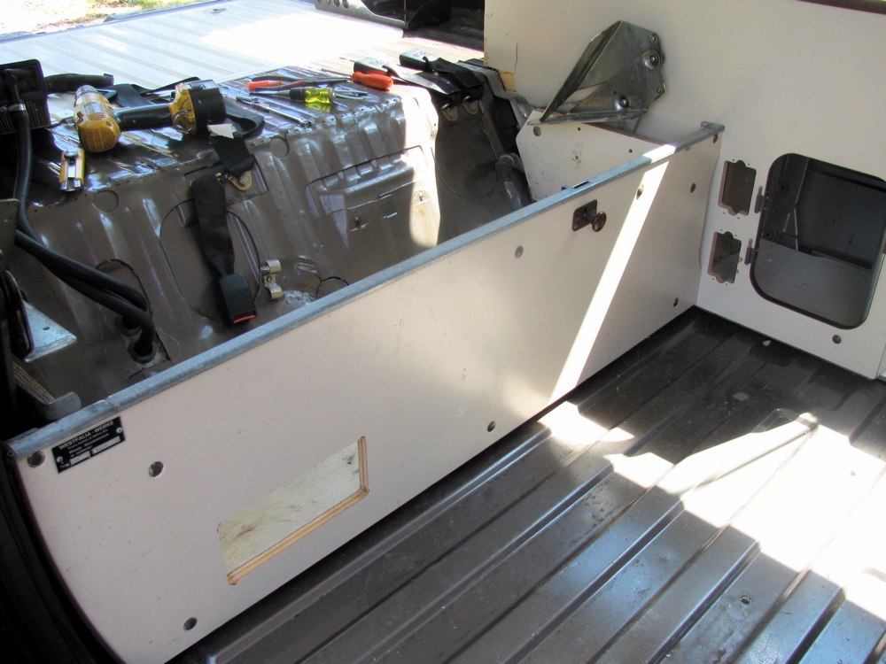
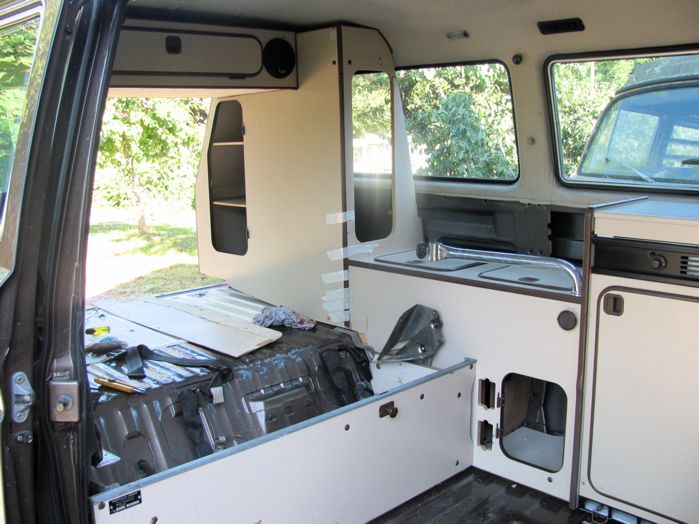
Rear overhead cabinet install
Posted by albell in vanagon, vanagon mods on August 14, 2010
With the way I am camperising my Syncro, ie just cutting sunroof sized hole, it means that there is no flat ceiling where the rear overhead cabinet goes. In the regular Westy, the flat ceiling is the plywood upped bunk surface, and the rear overhead cabinet bolts securely up to it as well as being bolted at the side to the wardrobe.
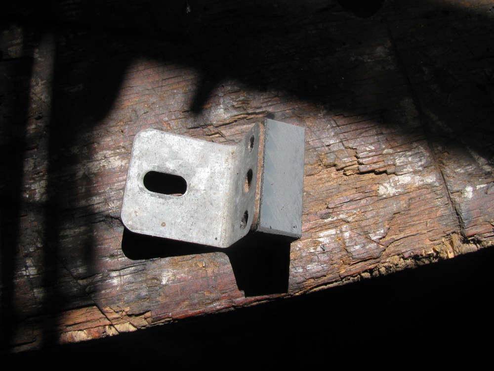
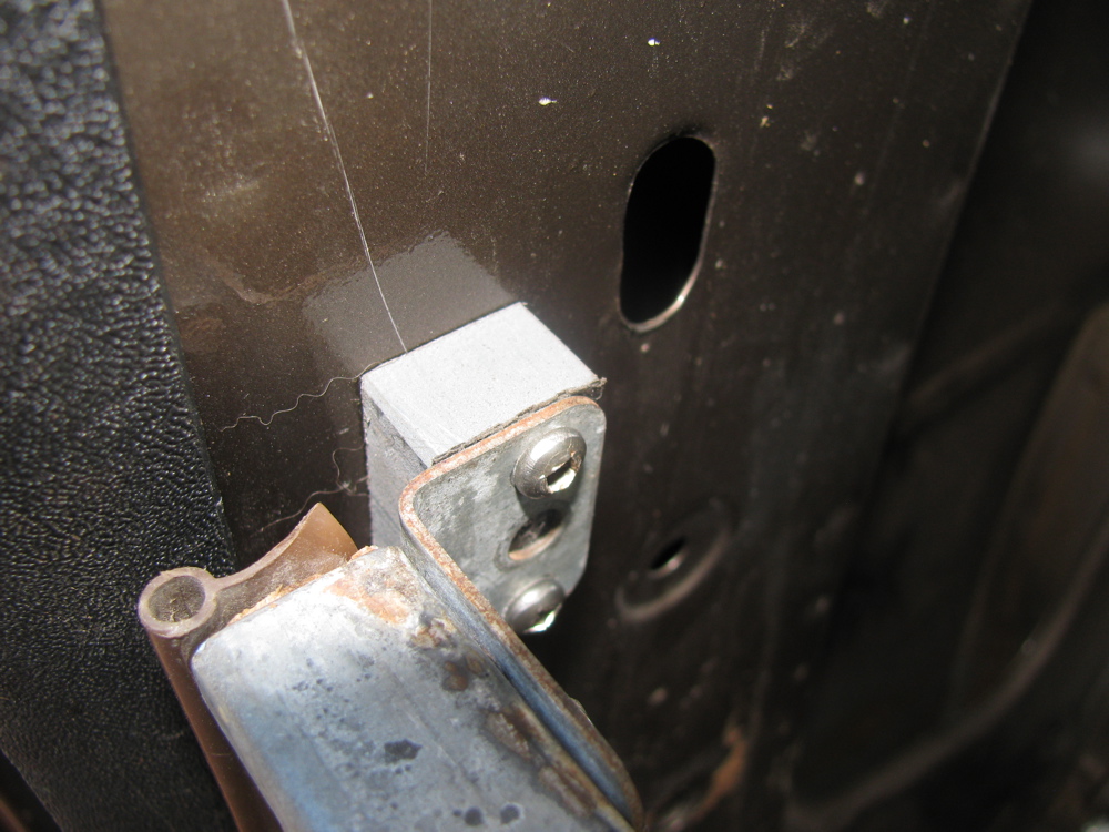
Having a headliner covered curved steel roof back there makes it a little harder for me to install the cabinet, and because the ceiling is not flat, my cabinet will have a space between it and ceiling. The Westfali Mosaik kit solved this problem by having a curved front face on the cabinet to match the curve of the ceiling, and uses rod like hangers to mount the cabinet to the van. Here is a diagram.

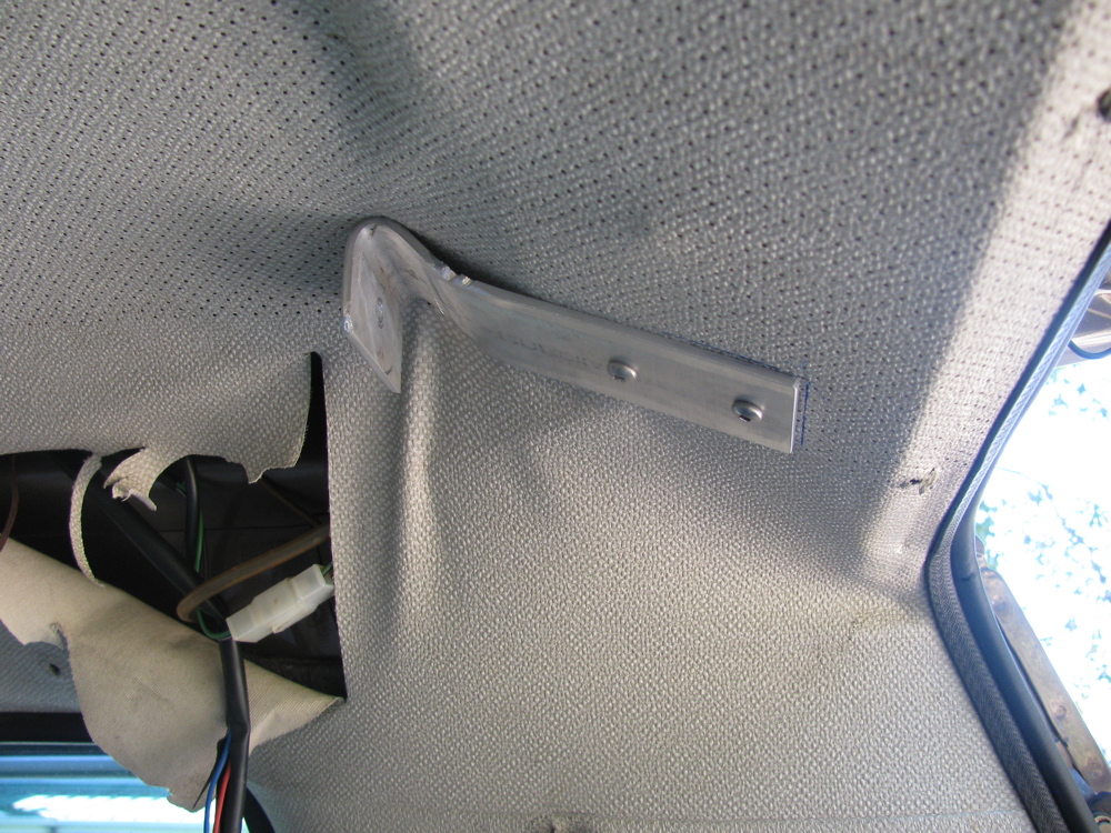
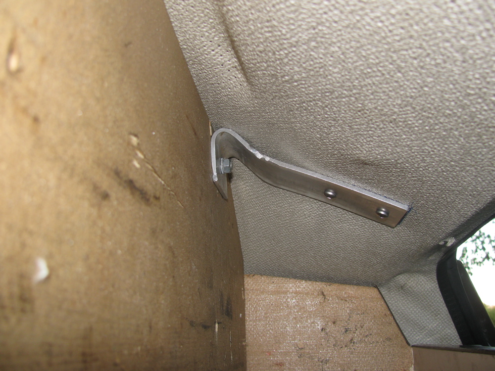
But, like and idiot, I couldn’t find the diagram above when I went to install the cabinet. I fussed over how to mount it securely – it was held on the wardrobe side by two bolts into top of wardrobe, but the other end was unsupported. I solved that partially by making a rather feeble bracket at the rear, right hand side. Its made from a ratty scrap bit of aluminium which had a tight bend in it, close enough to the angle needed. It was very awkward to fit and did not fully support that end of the cabinet.
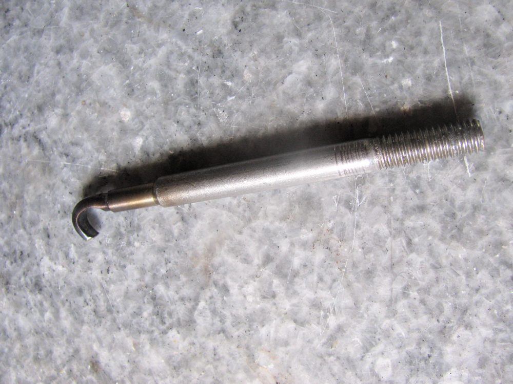
Later I found the diagram and made a hanger from a 3/8″ stainless bolt, and one of the brackets used in the rear AC electronics. The hanger hooks up and onto the box section reinforcing part of where the wall meets the roof. I may have to adjust things a little, I detect a slight misalignment, but all in all this worked well, the cabinet its fully supported.

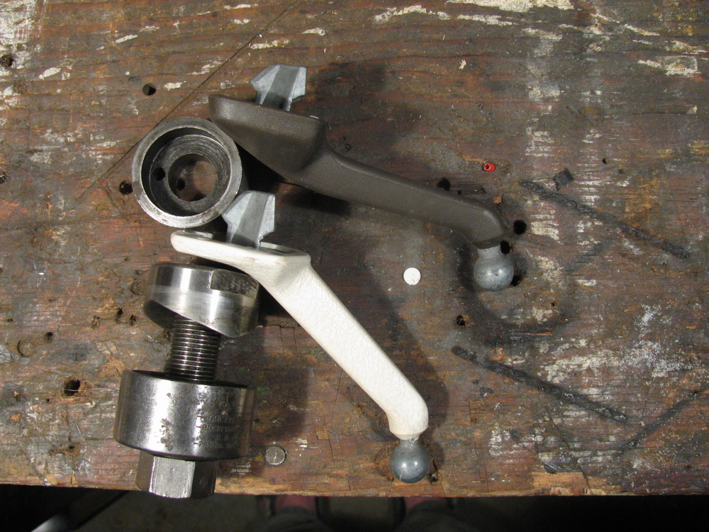
Westy rear view mirror mod
Posted by albell in vanagon, vanagon mods on August 12, 2010
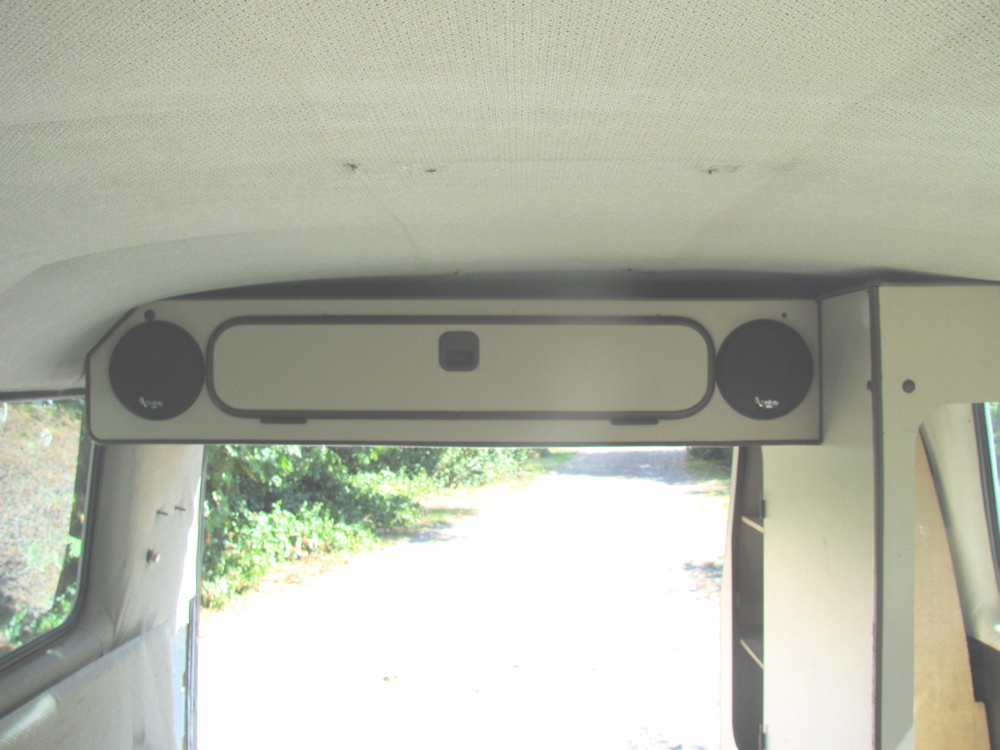
The rear overhead cabinet or AC unit in the Westfalia reduces your rear view (huh? you know what I mean) and that bugs a lot of folk, including me. There was a Samba thread on this subject with some good solutions. One was to use a baywindow van mirror stalk, there were some that had extended stalks and this is the hot ticket. I have a ’72 westy gathering moss with regular sized stalk, so I removed the rear view mirror – clockwise twist on stalk – and tried it our with the Vanagon mirror (why on earth had I not bothered to do this before you ask? I guess I’m slow).
The ball joint between the mirror and the stalk are the same on both, and the mirror comes off with a little bit of twisting.
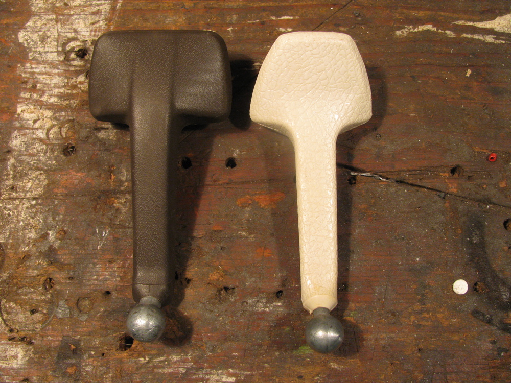
The baywindow stalk is perhaps a tad longer than the vanagon’s, but the attachment angle is different. The upshot is it may provide a bit better rear view. Pictures to prove this assertion to come, but for now some pics of the stalks. The baywindow stalk in off white, the Vanagon in brown.
Update: took pictures of both stalks (same mirror) in van. The shots from drivers point of view, showing rear visibility are crap, sorry. Don’t know if you can tell that there is improved viewing angle, but I think there is. The side views show clearly the different angles of the stalks. If you have a spare baywindow stalk lying around its worth trying it out.


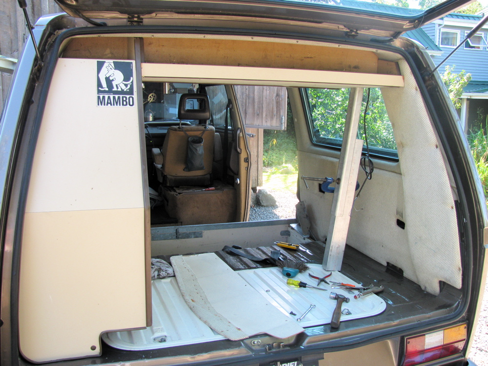
Westy new old floor
Posted by albell in vanagon, vanagon mods on August 11, 2010
I couldn’t help myself, this evening I put the floor tracks and the old floor I made for my ’82 Westy (original “82 Westy floor, cut into 3 strips, faced with luan door skin plywood, and shellacked) into the Syncro. The floor has weathered pretty well, mind you it has been covered by foam and carpet, but still its 10 years old.
I need to do some minor fitting to get it just right but now the camperisation is really coming together.

Here’s what I wrote in my old web site about the floor in the old “82 Westy:
“Back in ’00, when I reno’ed the interior of my van, I replaced the foor.
Early Westies (like my ’82) had a floor made from carpet covered plywood. Later vanagons had a “floor track system” that I thought was useful as it allowed the installation of a stand-alone seat, or a second bench seat.
So I got the tracks from a wrecker (they are bolted to the steel floor of the van) I ripped the original (awful quality) plywood into three sections, faced them with luan plywood (3mm doorskins) and installed the whole shebang. The luan ply is finished with shellac and wax. I trimmed the original carpet to lay on top of the new floor.
The shellac and wax finish has held up surprisingly well but is quite slippery, doh! The carpet would slip around on it until I installed a foam flooring material discovered at the local Home Depot (I had originally wanted to face the ply with some cork flooring – still will someday).
The foam is about 3/4″ thick and the edges interlock together. I don’t know what kind of plastic it is made from, but it is like a beefed up version of those foam jigsaw puzzles for kids.
One package (around Ca$19) makes a square about 4 feet by 4 feet, not quite large enough to do the Westy floor perfectly, but it works fine.
The foam just lays on the ply, trimmed a little to fit the cabinet projections and stops the carpet from slipping as well as providng a very nice feel to the floor. Also, it comes right out with no fuss and can be used as a seating/lying/playing pad when camping.”


Camperisation Part 2
Posted by albell in syncro, vanagon, vanagon mods on August 11, 2010
I did some trial fittings and screwed down some cabinets in final positions. Made a spacer for bracket that holds pass. side of rear bench to wall of van. I mentioned in “the start of camperisation” post that the rear bench did not fit as tight to the wall in the syncro as it did in the ’82 Westy. The spacer allows the bracket to be used and bolts the bench tight to the wall.
Wardrobe actually fit in without cutting headliner. Bracket at back on engine deck is fixed in place, and wardrobe is bolted to next cabinet and that cabinet is bolted to rear bench. Its alll pretty secure even though low cabinet not attched to van wall yet and also the rear bench is not bolted down to floor yet.
Overhead cabinet bolted to wardrobe and held up on other end by prop until I figure out a support bracket to hold it to ceiling and to pass. side wall. In the Westy, its bolted to flat ceiling (plywood) which is the upper bunk. You can see how the ceilings differ in that there is a space between overhead cabinet and the ceiling. The Mosaik “kit” has a differently shaped cabinet face to account for ceiling difference. (I can’t seem to find a pic of that modified cabinet right a the moment) I will have to do something to fill gap between cabinet and ceiling.
Apart from little fitment issues, the cabinets went in pretty easily. Next step is making holes for propane lines and watertank and sink drains.
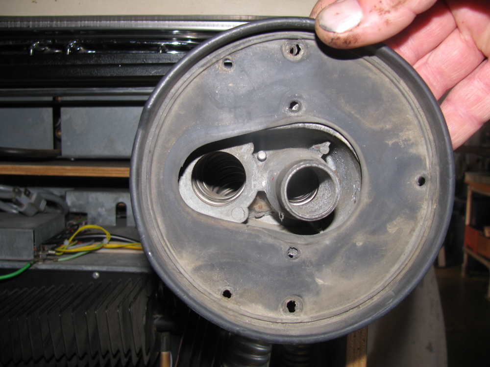
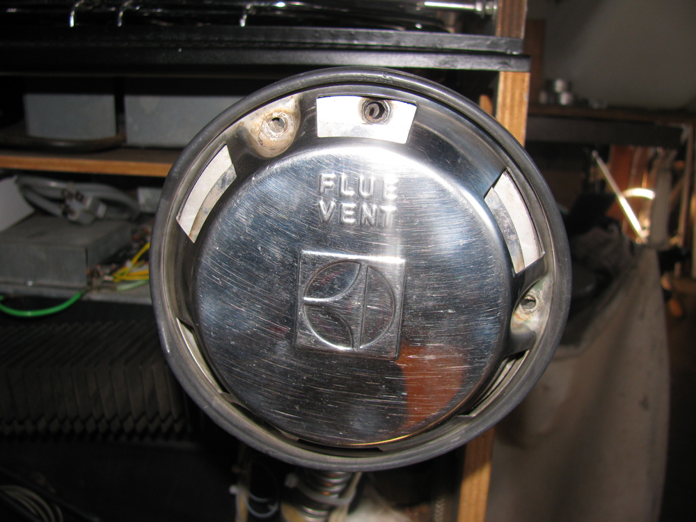
Dometic fridge flue assembly
Posted here just for vanagon list discussion…
Assembly of flue, pics taken with fridge out of van. In van you would see fridge exhaust showing through hole in van wall. Try and arrange the exhaust to lie slightly inside wall, and exhaust and intake vents horizontal. The rubber gasket is placed on the van wall ( caulk backside of gasket with silicon or similar), then the next plate is offered up and the 2 machine screws inserted to pull the plate tight to the van wall. By the way, the threads in the holes in the exh/intake manifold are often pretty worn out. I found a 10-24 tap will cut new threads without drilling. You’ll need new screws of course, get stainless. You can see what I used in the pic. Then that plate is screwed to van wall by 2 sheet metal screws (the holes in van wall may be oversized, need to get bigger screws, and get stainless. Same thing with the 3 final screws). Next comes the plate with the offset hole. It only goes on one way and has to sit in the ridge on end of exh. tube. I find it easiest to put this plate on at same time as vent cover, holding the two in place with fingertips through vent holes. When assembled correctly, that trapped plate is held in place when the vent cover is screwed into van wall.


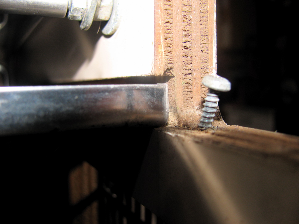
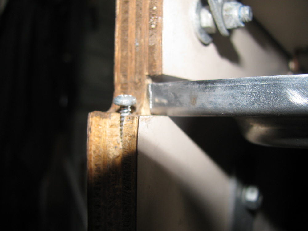
Westy sink/stove top rattles
Posted by albell in vanagon, vanagon mods on August 11, 2010
Every Westy owner knows that the stove top rattles when you’re driving on bumpy roads. The rattling can be reduced by:
– making sure latch on top adjusted properly
– installing new rubber/foam bumpers under lid front edge
– laying a tea towel or sponge on stove grate before closing top
– making sure that drain tray in held firmly by bullet catches in lid (not applicable to Canadian market versions)
The rattling comes mostly, I think, from the stove grill and drain tray. But looking at the kitchen unit on the bench, I could see that the groove that the stove top sits in the cabinet is wide enough to allow the rear of the stove top to move up and down a couple of millimeters or so. The front fo the stove top is held firmly by the metal front panel (or should be if all the screws are in place tight), but the rear is only held by one screw to the back grill that runs the full length of kitchen unit. I tightened up the fit of the stove top in the groove with some thin plastic shims, silicon caulked in place. Pics show left and right sides, the gaps and the fix. The rear grill was removed.

Westy Dometic fridge performance
Posted by albell in vanagon, vanagon mods on August 11, 2010
A few years ago I recorded the temperatures inside and outside the fridge just to see how well it works. Data shown below. Unfortunately I did not record what I meant by “back fan on”. Was it the fan on the cooling fins on back of fridge? I think so. But was it cycling and what was the cycle period? It might have been the fan I added to the external water supply port on van, but I doubt it. Nothing worse than half assed experiments eh?
Oh, almost forgot to add, this is with fridge on propane power.

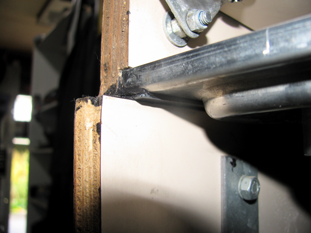
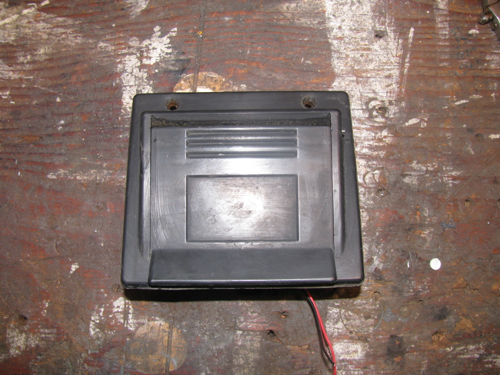
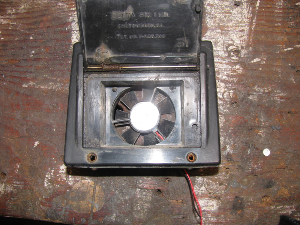
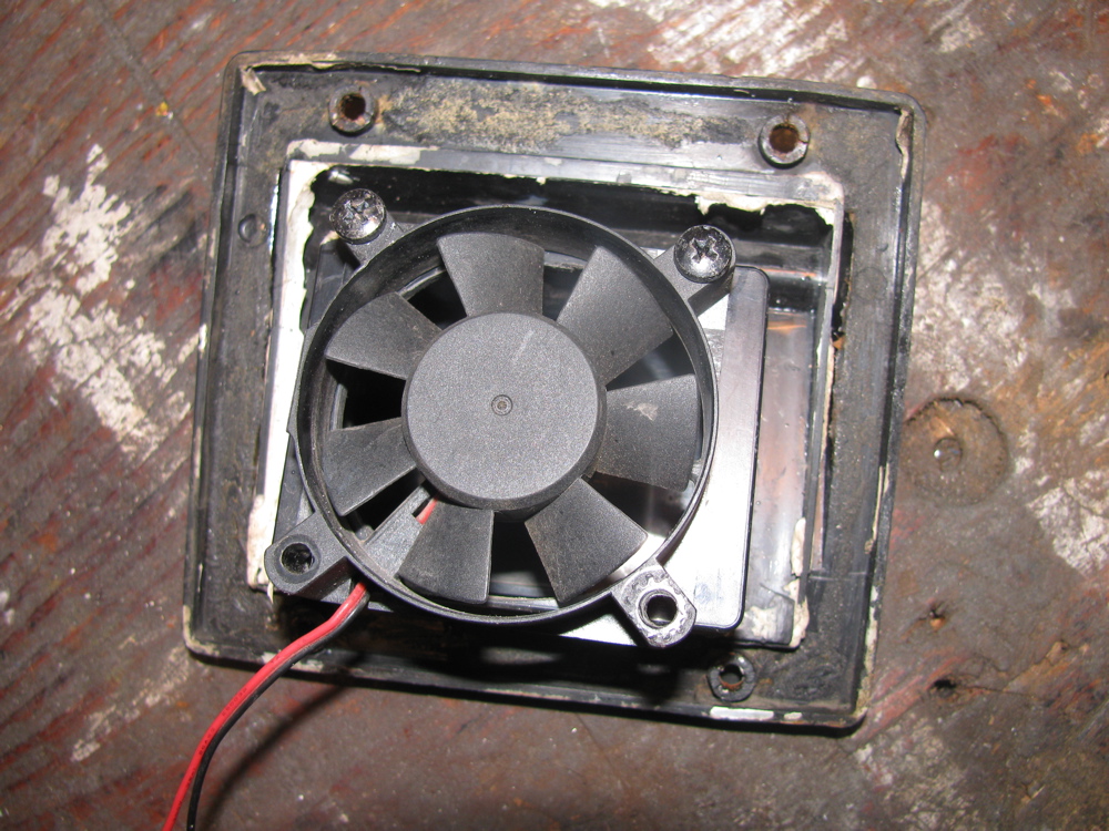
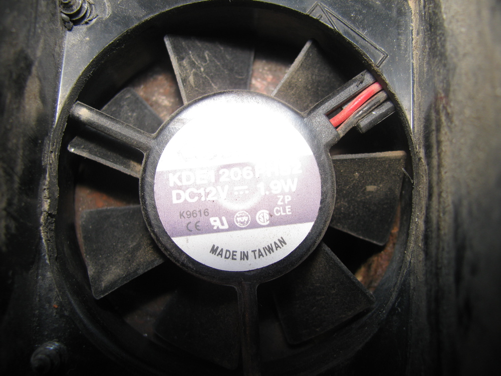
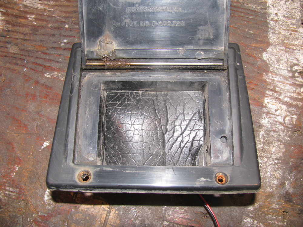
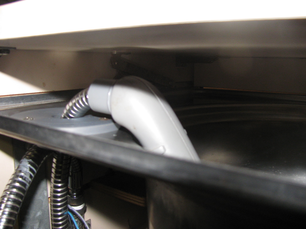
Westy city water port fan mod
Posted by albell in vanagon mods on August 10, 2010
In last post I talked about how well a fan in a modified city water hatch/port works to cool the back side of the fridge. I pulled the port from my old Westy to take pics to show… fan was initially wired in parallel to fridge cooling fan, but later I put it on its own manual switch. It is oriented to blow air out of van. Hatch is propped open by a square of foam material which doubles as a gasket when hatch closed.
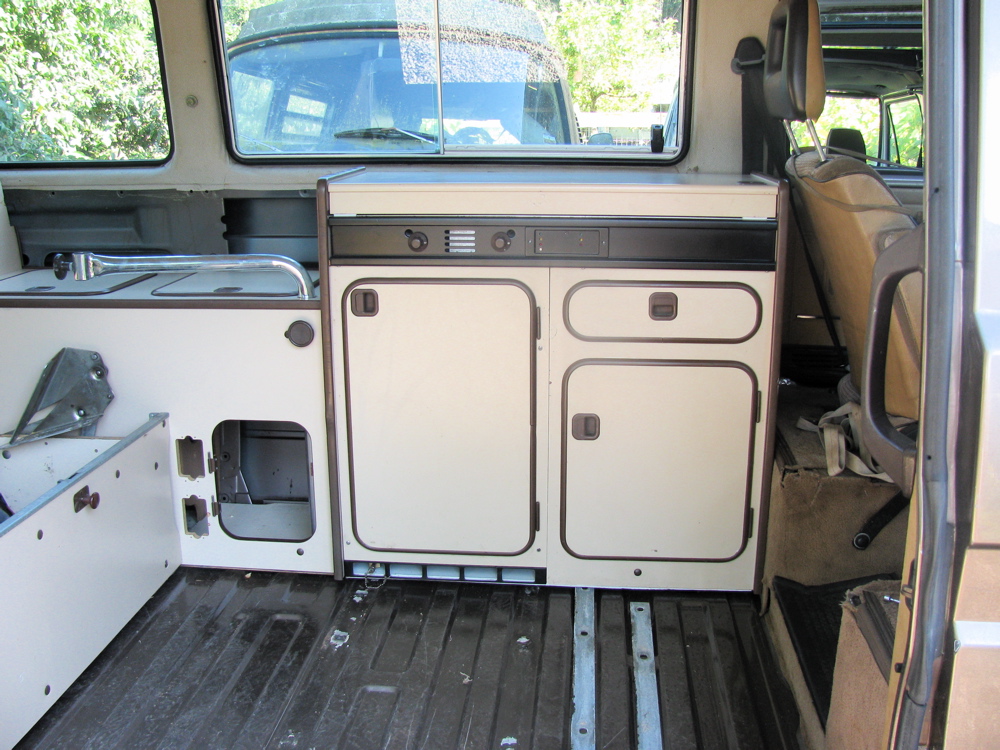
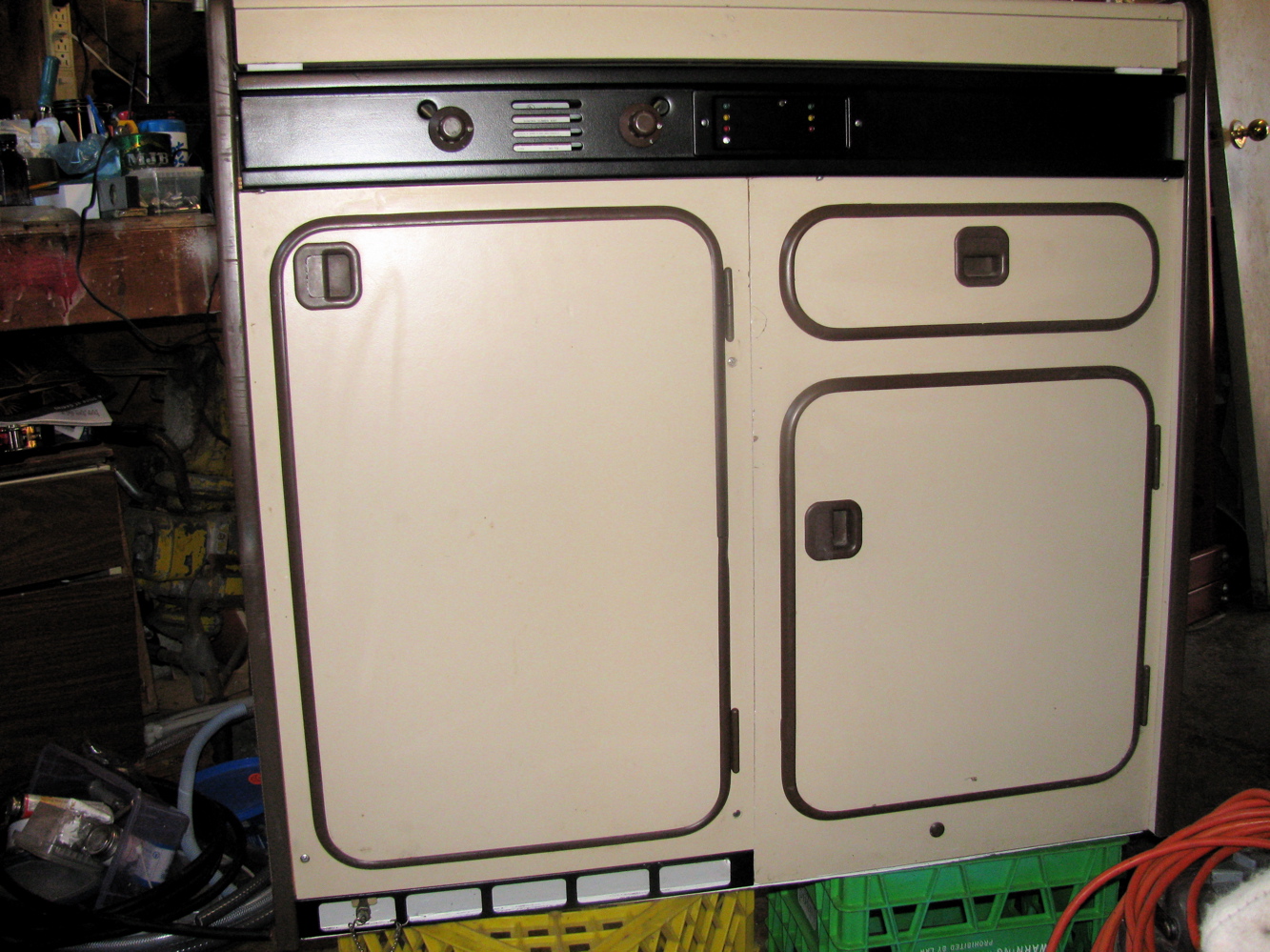
Westy kitchen unit clean up
Posted by albell in vanagon, vanagon mods on August 8, 2010
Spent some time cleaning up the fridge, sink, and cabinet. I added another muffin fan to fridge cooling coils. I’ve had a muffin fan installed for a few years since the original fan crapped out. These muffin fans do not move as much air as the original, but they were free, and as an experiment I decided to add another in parallel. It is cable tied to the second row of cooling fins, with some foam to isolate noise. I am sure the foam will degrade pretty quickly, but we’ll see before that if 2 fans arranged thus is better than one.
Over the years, I’ve done a fair bit of dicking around trying to get more air over the coils of the old fridge, and now I am back to pretty well stock. Best modification I ever did was to use the westy external mains water connection port as a vent. I took out the plumbing and put in a small fan. This really did get the hot air out from back of the fridge. But I don’t plan on cutting a hole in the syncro to do this mod when I install the cabinets though.
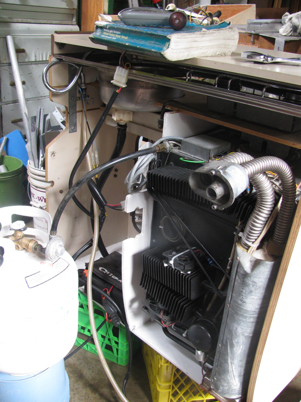
Other notes, water line to faucet fixed down to cabinet, and I never did find a good colour match for the brown on the metal bits… exasperated, I sprayed with satin black wheel paint. If I ever find a good brown paint match I’ll re-spray. The black looks a bit funny.
One pic shows propane tank and reg. connected to fridge, and small battery pack powering the electrical system. The fridge lit up easily and started to cool down nicely. Its amazing for such an old unit (1982) which has had a pretty well used life (you can tell by the tatty state of the cabinets) that it still works as well as it does.


Eurovan faucet in Vanagon Westy sink
Posted by albell in vanagon mods on August 7, 2010
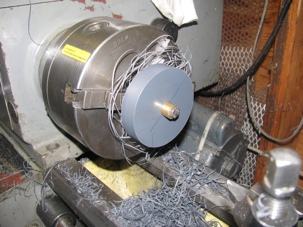
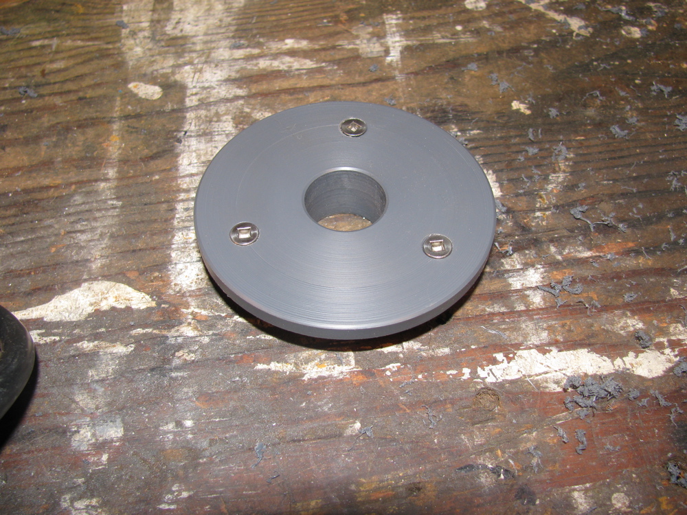
Years ago I bought an Eurovan faucet at a wreckers for a few bucks. Was a good deal except it had no control knob. I made a simple knob on the drill press, out of some phenolic impregnated plywood and never got around to installing in my Westy sink. Finally I am, first I needed to make a flange type bracket to go in the stock faucet hole to hold the detachable Eurovan faucet. Its some PVC scrap. Pics tell the story, next job is to connect the pump wires and the water hose. Oh, one problem with this unit is it has to be laid in sink to close lid. See Gary Lee’s install.


Syncro fuel filter replacement, Part 2
Posted by albell in syncro, syncro specific repairs on August 4, 2010
Got the new filter today, and after working on my wave maker project I set about putting it in.

Installed into bracket.

Tucked behind spring tower, fuel line outlet attached first.

Then filter pulled forward towards front of van and inlet line attached. The the bracket moved into place and attached to tower with the screws. Do the rear screw first, then the front screw. Rear is towards rear of van, front is towards front of van.


Next is reinstalling carbon filter/canister bracket.

And finally the canister itself. I think I installed it higher on the bracket than before, but I don’t think I have crimped any of the lines at the top of the canister.

Overview shot of area.

In hindsight, I guess its not that bad of a job. But I can imagine it being hell with a van that has seen more salty winters. While I was in there, I removed an A/C line and the A/C drier that sat behind the charcoal canister, I’m stripping all the A/C stuff from the van.
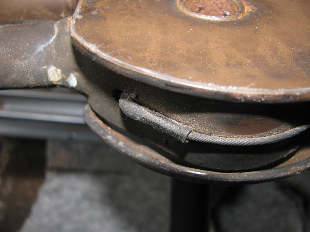
Pop top strut cable fitting
Posted by albell in vanagon mods on August 4, 2010
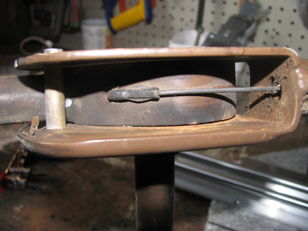
For fellow listmember Neil… pics of “Z” fitting on end of cable on an old smoke stained (junkyard find) pop top strut assembly. This is the fitting you are trying to reproduce Neil?
Rear seat/bed bracket attachment
Posted by albell in syncro, vanagon, vanagon mods on August 3, 2010
I mentioned before that just drilling a hole through the sheet metal of the rear deck to attach the rear seat/bed brackets is not good enough to get a firm connection. The screws used are self tapping screws which sort of implies, I think, that the factory did not weld on nuts on the underside of the sheet metal. Looking closely into the holes in my ’82 Westy the metal appears thicker than in the same place on my ’86 syncro. Here is view from inside of van of one of the brackets in place (in place but askew).

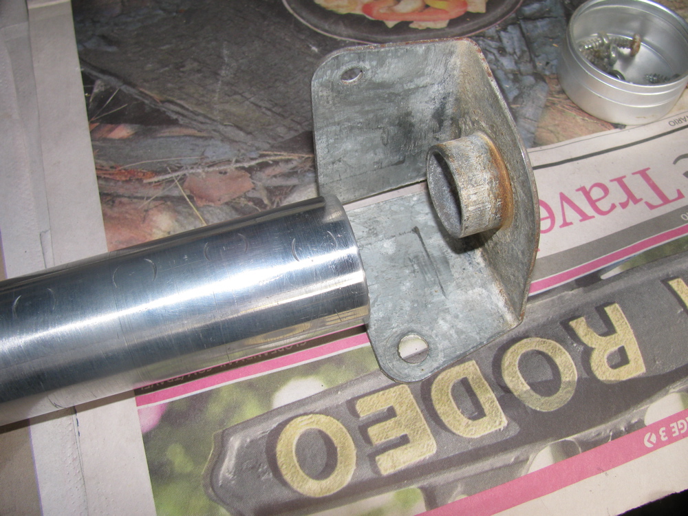
So I set about making some little backing plates to give the screws more thread to love. I used 3/16″ thick stainless bar to make to little plates, 3/4″ wide, 1″ long and a hole in each tapped for 6 X 1.00 mm thread. My plan was to use some Sikaflex to glue the plates to the underside of the deck so that the would stay in place when I screwed the the brackets down. Here is exciting picture of one of the “plates”.

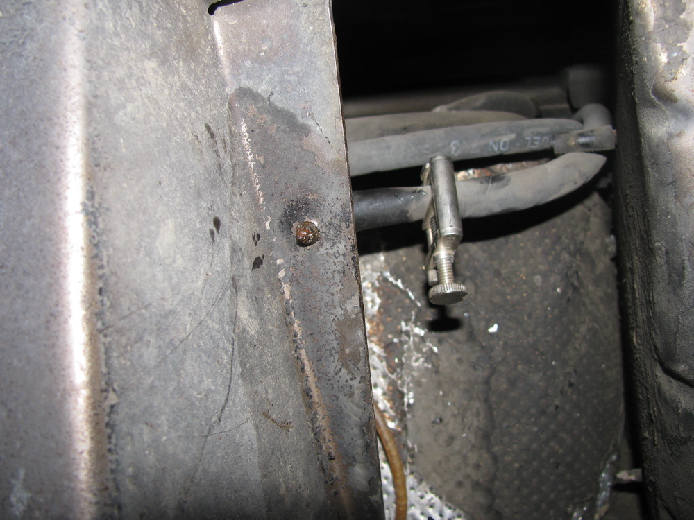
And here is one of the little chaps stuck up in the passenger side rear wheel well where the right hand bracket screw comes through – boy am I slow, it just occurred to me now to check the same place in the Westy to see if there is any similar thing going on. Edit: I just looked at the passenger side rear wheel well on my ’82 Westy where the bracket screw comes through, and lo and behold, looks like a nut is there, surrounded by goop. I assume same thing done for other bracket. So I am not completely mad thinking my little plates will work.
My plate:

Westfalia’s version:

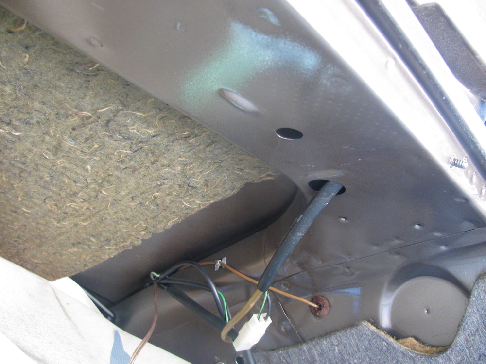
On the driver’s side, the screw comes through above and behind the gas tank of the Syncro.

And here is the plate in place, all smeared with Sikaflex.

I’ll let the Sikaflex cure overnight and then I will remove the screws and I hope the plates will stay in place.
Syncro fuel filter replacement, Part I
Posted by albell in syncro, syncro specific repairs on August 3, 2010
The design team responsible for the fuel supply system in the Vanagon Syncro was led by a descendant of Leopold von Sacher-Masoch. No? Well how do you explain the location of the fuel filter then?
In camperizing the syncro I came upon the problem of screwing down the folding bed/rear bench brackets to the rear deck. I mentioned in a previous post how I drilled and tapped holes, but the rear deck is not thick enough to get more than one complete thread in it, so I went about making some little backing plates to build it up. On the passenger side it is no problem, the area is in the wheel well. But on the drivers side you have to reach up in wheel well, past the carbon filter and behind/above the gas tank. While doing that I decided to change the fuel filter which is located in that region.
Actually the fuel filter is attached to the inboard side of the spring tower. But you wouldn’t know it from this diagram (its #25, oh and the charcoal filter which is part of the emission control system is not shown here).

I did not take an “establishing shot” type pic, but here is a close up of the front side of the spring tower and the charcoal canister (I had removed the gear clamp that holds the canister to its bracket, which in turn is screwed to spring tower).

With the canister moved out the way a bit, you can see the filter, inlet end.
 And if you peer around the rear of the spring tower, you can see the filter outlet end.
 See that screw end sticking out? its one of two 10 mm hex headed screws that holds the filter bracket to the spring tower. I took both out, the “other one” near the front side of the tower is a bit awkward to get at, but I was lucky in that they were not rusted in. By the way, I did squirt all the fasteners with some rust busting stuff before starting. Hello bracket end!
 I clamped the inlet and outlet fuel lines at this point too. I could get at the gear clamp at the outlet side so I removed that hose from the filter.
 Then I struggled with pulling the filter forward, towards front of van, and down to get it out.
 The above picture shows how it doesn’t come out. The charcoal canister, like an annoying relative, kept getting in the way, and the canister’s bracket to the right prevented the filter from coming out… oh wait, why not remove that dammed bracket, doh. Again, two 10 mm hex head screws, and the bracket is off and the filter and its bracket comes out.

 I removed the filter from the bracket, sent the bracket and the charcoal canister bracket into a wash of naval jelly in preparation for painting. Here is the filter still in its bracket and beside it, the charcoal canister bracket.
 Part number for the fuel filter is 450 905 030. Its used an a number of VW vehicles from the 80’s/90’s, should cost around 10 – 15 bucks.
Freed from its bracket, the filter underwent surgery.
 The exposed paper filter elements were incised then retracted.

Yuck. I bet its the original filter.
The brackets are painted and now drying, tomorrow the new filter goes in. See that in Part II
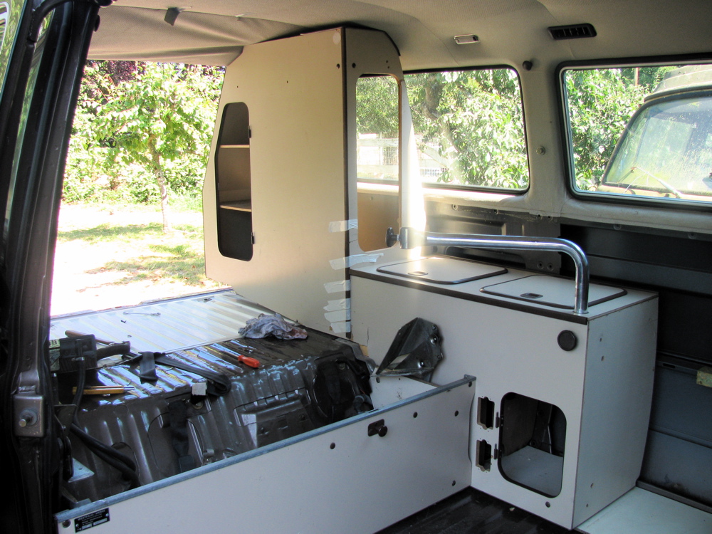
Start of the camperization
Posted by albell in syncro specific repairs, vanagon, vanagon mods on August 2, 2010
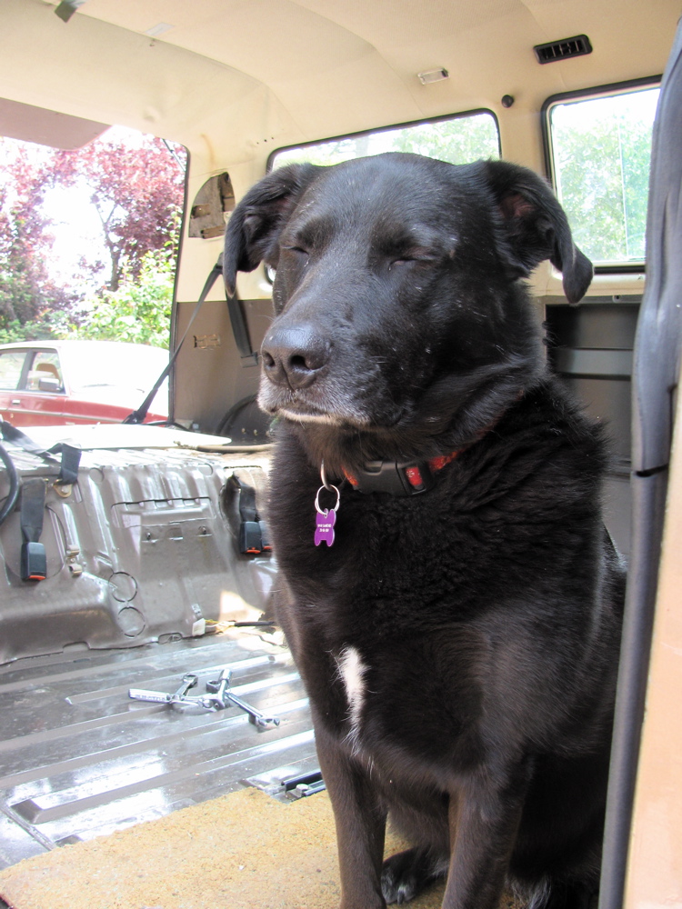
Finally… getting round to putting the innards of my ’82 Westy into my ’86 Syncro. Cleaning out the Syncro, the rear seats removed (boy they are heavy) and having a gander at just how much work it will be to put in the Westy stuff…
A few notes:
-the Syncro’s ECU looks like it was installed yesterday
– the rear heater had a bit of dried up coolant at one of the hose connections. I pulled the core just in case it was leaking too. The core had a date stamp of “00” so I am assuming it was replaced 10 years ago. Closer examination showed that the core was sound, but I swapped in a fresh one – an Iltis front heater core, same part number as Vanagon rear heater core – that I got at a govt. auction. The “old” core has a better construction method, the end cap opposite the valve covers return tubes, where as the “new” core I put in has the end cap being part of the return path… so if that end cap fails we get leakage.
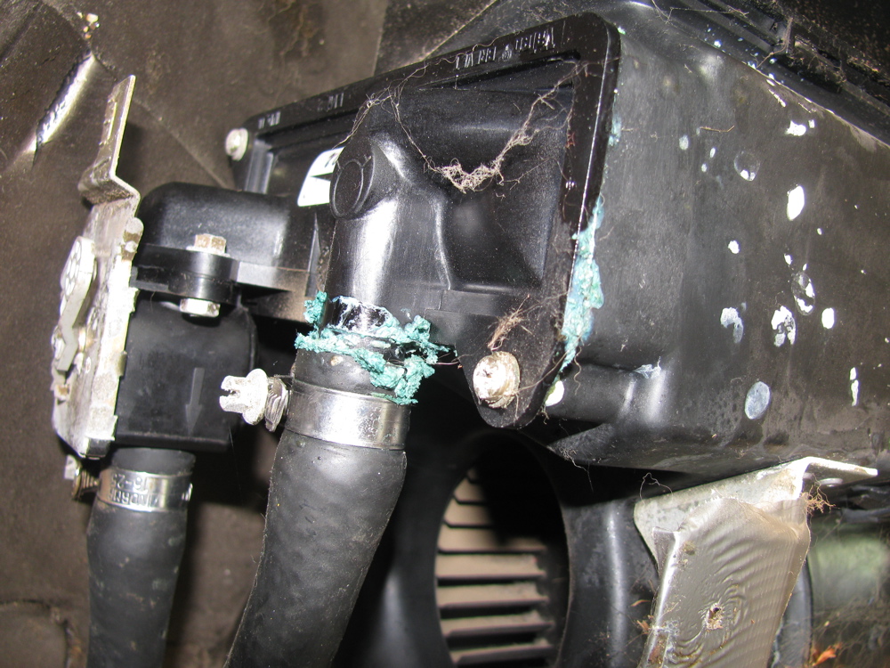
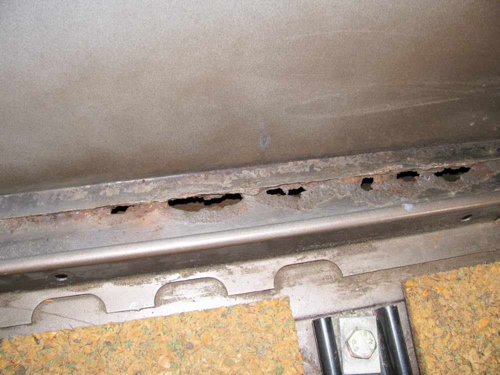
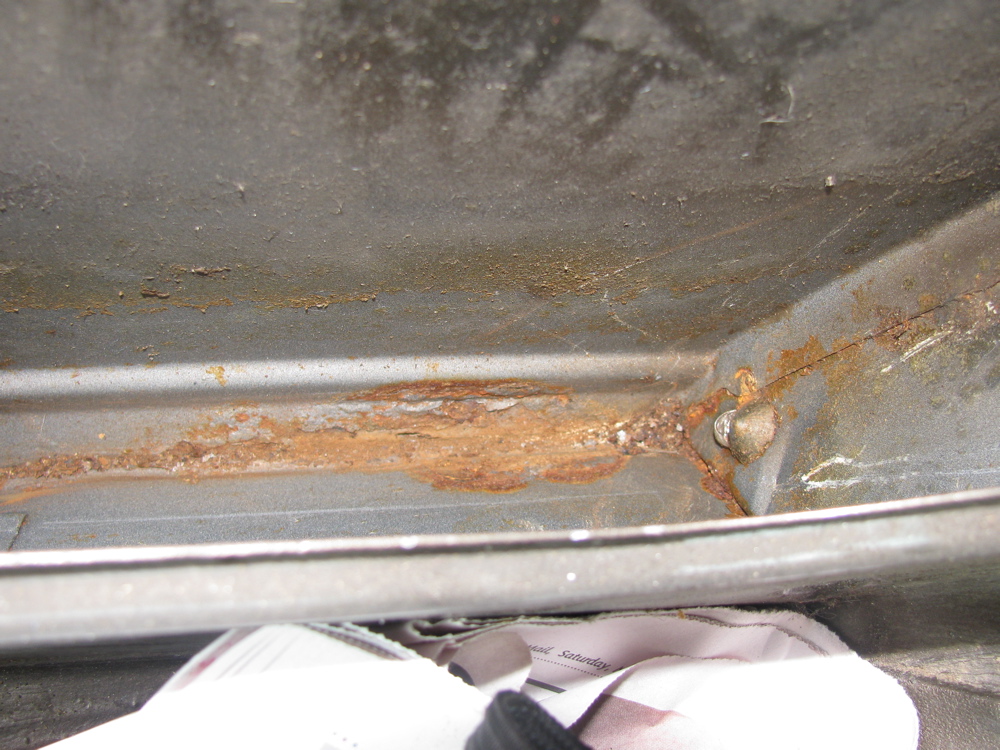
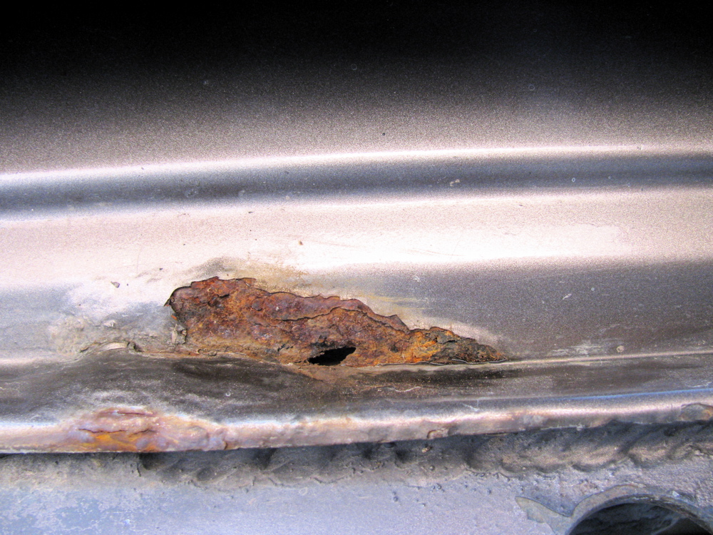
– leaking rear window washer reservoir had caused rust severe rust… Was like that when I got the van. To be precise, it was the pump that was leaking, I spent 5 minutes mucking around trying to seal the bugger, but hen found out they are pretty cheap and available.
– rust on drivers side inner lower seam worse than I thought. Again, I know, I know.
– the rear bench sits in ok, and I measured the holes in the Westy were the hinge brackets attach to the rear deck and drilled in the Syncro deck (after cutting out a bit of the asphalt based sound deadening stuff). I tapped for a 6 X 1.0 mm thread (not much threading meat available on the deck, there must have been a backing plate on the Westy, I’ll see about doing same on syncro) and I screwed down the brackets. Well, it turns out that now the bench sits away from the pass. side wall more than it should. I remeasured the holes and found that on the old Westy the hole is 5 mm further inboard than on the Syncro. Funny eh? Both sets of holes are centred in the “same valley” . Something must have changed over the years. I have noticed that some Westys have a trim plate on the side of the bench, this might have been Westfalia’s answer to some body change VW made. I have one of those trim plates, I may use it.
-I tried the wardrobe fitment, and it looks like it will fit with no modification, even though I don’t have the Westy modified ceiling. The headliner might need cutting though.
-I tried a panel from Westy… I recovered most of the interior panels on my old Westy about 10 years ago, its held up well and I may re-use them.
Many other little details to iron out, but nothing difficult


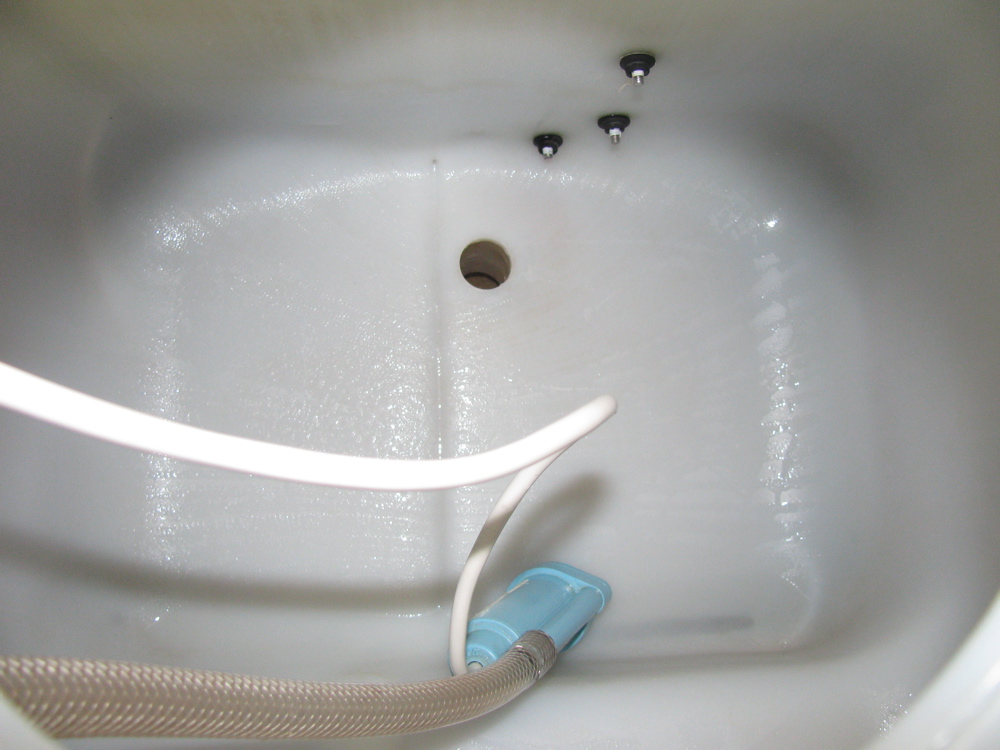
Westy water tank cleaning
Again, with all the Westy stuff out of the van and scattered around the place, I can do things easier… like really cleaning out the water tank. Over the years I have used chlorine bleach and more recently sodium percarbonate ( much nicer) at least onec a year to keep the tank reasonable “sweet”. But with the tank out, I could see grunge in the bottom grooves formed during casting of the tank. It looked like hard water deposits, so out with the heavy guns, HCl. Not too much mind you, mixed with water, but I can’t give the molarity of resulting solution. It did take care of the deposits and cleaned up the level indicator electrodes. You don’t want to be scrubbing a plastic tank like this with abrasive cleansers, that scratches the plastic and give dirt etc more places to cling on to.

Westy table mod
Posted by albell in vanagon, vanagon mods on August 2, 2010
I have all of the Westy interior out of my ’82 Vanagon now, and I am going over the parts in preparation of installing them into my ’86 Syncro. Some of the cabinetry was damaged in the accident I had with the Westy that took it out of commission. I was hit by the front end loader on the driver’s side, just in front of the rear wheel, so the Westy “wardrobe” and the low cabinets just forward of the wardrobe got a bit banged up. I’ve patched them up to be structurally, if not cosmetically, sound. While I have the cabinets in the shop I thought I might do some of those old modifications I never got around to before.
The first one is a modification to the table clamping system that allows the table “leg” to extend up and let you get into those top loading cabinets. This is not my idea, many others have done this. There are 2 ways to go about this, one is to install a rod, fixed to the lower mount of the table leg and the rod extends inside the table leg itself. The other route is to use some tubing, fixed between the upper and lower mounts, which the table leg inserts into. I chose the latter approach as I had scrap aluminium tubing lying around. You can see in the pics that I made a collar to join the tube to the upper mount. The collar is a close fit to both the tube and the upper mount. The table leg is a nice tight fit inside the tubing, actually tighter than I would have liked. Either the table leg or the tubing must have a slight bend for its a tighter fit when installed than I found when I tried the combo with a short bit of scrap tubing. Oh well, at least there will be no rattles.


