Archive for June, 2011
Vanagon syncro – transmission oil change with complications
Posted by albell in syncro, syncro specific repairs on June 24, 2011
A very brief overview of a transmission oil change in my ’86 syncro. I had not changed the oil since I bought this van almost 2 years ago and I noticed a very slight oil leak/seep at the bottom edge of the reverse gear cover plate. I figured it would be worthwhile when I had the chance to drain the oil and look at the cover plate. I bought some regular run of the mill 80/90 wt gear oil with the idea that I would put in the fancy gear oil later after I fixed the cover plate leak. As it turned out, this was a smart move.
The oil fill port is on the right hand side of the van just above the shift linkage rear bushing. The drain port is near the rear near the midline. Important to first see if you can unscrew the fill port before trying the drain port. To get at the fill port easily I found it best to remove the rear skid plate/bars; 2 X 17 mm nuts and bolts at the engine carrier bar, 2 X 17 mm bolts and 2 X 17 mm nuts and bolts at the forward end of bars( actually there is a 15 mm nut on the upper left hand skid bar mount), and to detach the shift linkage rear bushing housing; 2 X 13 mm nuts and bolts.
Kinda silly picture of skid plate out.

Oh, I should mention the tools I used to remove the drain and fill plugs. A 17 mm allen key, and a nice Snap-On tool with 17 mm hex. I needed the allen key to help the Snap-On tool at the fill plug, there was not enough space to fully swing the wrench (you know what I mean).

And more obvious advice: clean out the hex recess in the plugs with dental pick, toothpick, compressed air, whatever. Ya gotta have the wrench make a good fit. I squirted penetrant/rust buster on the plugs, more out of habit than expecting that the damn stuff actually does anything. Next pictures shows the fill plug (shift linkage still up in place) and the wrench in in the plug, riveting story eh?


Thankfully the fill port plug unscrewed with no problem. Next, on to the drain plug. The wet spot is the penetrant fluid stain.

It too came out with no trouble. The magnetic plug had a bit of fuzz on it, but I think this is a pretty normal coif.

While the transmission drained, I removed the weeping cover plate. It seemed to be leaking at the bottom edge.

Plate off, evidence of silicone caulk as a sealant.

Close up of the bottom corner that I suspected the leak was coming from. No smoking gun that I can see, minor scratches, almost a crack like line there though, no?

At this point I was advised by my son that I need to drive him to some sort of “date”, grrr. I should have let the transmission drain overnight and degrease the mating surface of the cover plate before applying rtv silicone and re-assembling (as per Daryl of AA transmission’s advice). So I slapped on the the silicone and the plate, and set about filling the transmission. I made a fill hose with some pvc tubing and a funnel.

All filled and the skid plate back on, the shift linkage re-installed, and the damn cover plate leaks more than before. So, tomorrow I’ll do it all over, this time properly letting the cover plate area drain and be de-greased. Daryl also advised flat filling the cover plate flange to make sure it is flat.

ATA – father’s day trip to BC aviation museum
Posted by albell in aircraft, around the airport on June 19, 2011
My son and I spent some time at the museum today. Here are some random pictures – Vickers Viscount, Douglas A26 Invader, Luscombe Silveraire, Pietenpool 1933, Willys Jeep, Allison V-12, Sikorsky S-55, super DC-3, aircraft tug.
Do I have to say again that the B.C. Aviation Museum is one of the best museums around here?


Vanagon – aux. light post updated
Posted by albell in vanagon, vanagon mods on June 18, 2011
I added my circuit diagram to my post on how I wired my aux. lights. Here it is if you don’t want to click on that link. Note: the diagram for the fog light switch is not correct in that the 3 position switch does not have the internals wired as shown, but the diagram works for the purpose now.


Bike – 30 years between them
The Cervelo is for sale BTW

Vanagon – westy luggage rack footman’s loops
Posted by albell in vanagon, vanagon mods on June 14, 2011
When the pop top was on my old ’82 westy I replaced the stock footman’s loops with some stainless eye straps, 2″ Harken, from West Marine, about $2.50 each. Here is Tiny URL to the catalogue page. I find them much better than stock, easier to run rope or attach bungees. The 2″ size fits pretty closely to the stock holes in the luggage rack. When I put them on originally (7 years ago?) I just had to enlarge the holes in the rack with a 5/16″ drill so that 1/4″ stainless bolts would fit. I dug out an old stock loop for a comparison.


Vanagon – Frank G.’s instrument cluster mod
Posted by albell in vanagon, vanagon mods on June 14, 2011
Another article from my old website
Frank writes:
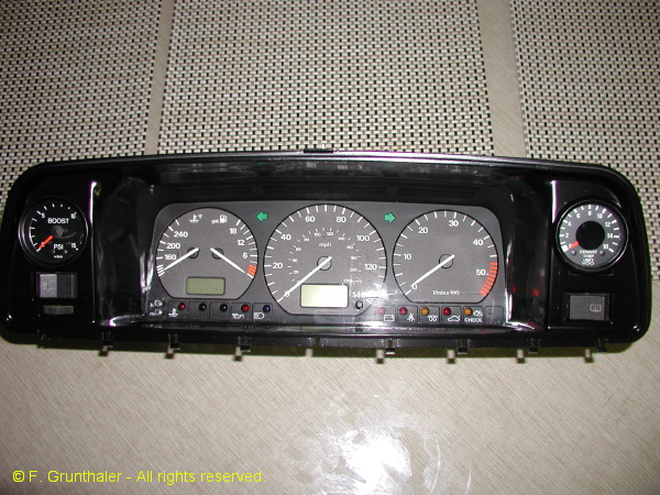
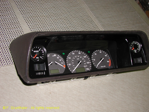
Just finished building a new Vanagon Instrument cluster for my TDi conversion project. I’ve always disliked the Vanagon instrument pod. The center section really offended my sense of completeness. Just looked fake. When I decided to divert the 2.0 Turbo Audi project to the TDI, I decided to do something about it. The result combines the instrument cluster from the 1997 Passat TDI (contributes the gauge faces and front cluster face), a 1995 Passat GLs (contributes the MFA processor calibrated for the 4 cylinder engine), a vanagon cluster, the bezel from a ’97 Passat and a set of VDO gauges.
I’m using the wiper (controls the MFA) and turn signal stalks (controls the cruise control) on the steering column from the 1995 Passat GLS 4-cylinder. Here in the cluster, the temperature and fuel gauges are combined, with separate speedometer and tachometer. The warning light group contains the typical diesel functions. There are two unused light ports. I’m doing transfer logos for them and adding my two color (red/green) LED’s. One of the lights monitors the radiator fan speed (green for low, red for high). The other follows the auxiliary lights with green for Fog on and red for the driving lights. The MFA monitors among the standard features, the engine oil temperature, the average fuel consumption, the instantaneous fuel consumption and the external air temperature. This LCD screen also displays the digital clock.
In the bezel, I add a boost gauge and a pyrometer for EGT measurements. In the lower dash plane I have two gauges, one on either side of the column. To the left, oil pressure and to the right, oil temperature monitored after the oil coolers. In the lower heater face panel, I have a set of five gauges monitoring voltage on the primary circuit, voltage on the auxiliary battery circuit, the pressure in the radiator coolant circuit, an analog clock and an LED compass direction gauge.
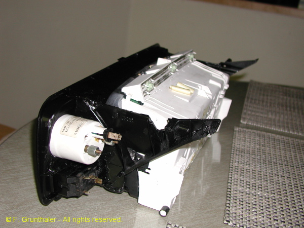
The speedo drive is electronic. I took the rear mount out of an old Jetta speedo cluster I had, cut it up tp keep the frame and the Hall magnet wheel. Then mounted them in a box to take the place of the EGR counter. I use the 3 wire speedo hall sensor from the G/J series. Its a bolt up (or screw up) to the speedo frame. A variable pulse counter frequency adjuster (circuit supplied by my son) will allow variable adjustment for a dead on speedometer regardless of tires and state of wear. Precision wirewound pot for frequency conversion adjustment. Calibrate with simple GPS.
Further notes on fabrication…
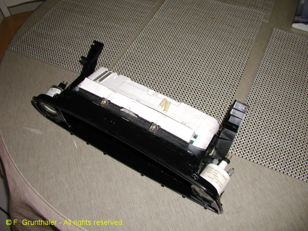
On the master cylinder reservoir interference issue … it was in the way and I wanted to maintain the visual angles, so I took it out! I then used a master cylinder reservoir from a ’90’s Mazda pickup. It comes (from your local P&P yard) with a remote mounting bracket. I rotated it so the long axis is parallel to the windshield long axis. It comes with a built-in level sensor that I wired into the VW harness. I can’t remember if the vanagon originally came with the level sensor built in of if I added it to the vanagon reservoir and modded the harness years ago. For the inlet lines to master cylinder, I believe I used the plastic barb adaptors from a Super Beetle. I use an inline T to tap off the clutch feed. I mounted the reservoir in the same general area as the original Vanagon unit and aligned the inlet so that the plastic drip shield fit again (anal-retentive, I know). Clears the back of the cluster as if it were designed to do so! This solution should work for any cluster one would like to put in!
On the choice of cluster…. Well to start with, I have always thought (going back to March of ’82 when I placed the order for Westfalia for factory delivery) that the instrument cluster was a tacky design. The fake molded sensor lights particularly irritated me! I later years, I added the tach, the oil pressure warning circuits, the VSS speed sensor and redesigned the warning light package to give right and left turn signal lights, added cruise control lights, finally adding multicolor LEDs to the fake center section to monitor radiator fan speed, intercooler fan speeds, fog and driving lights and A/C control parameters. But I never liked the look of the thing.
When I decided to TDi the Vanagon, my orders to the salvage yard were that I wanted it all – engine, hoses, all wires and sensors. To my surprise, they included the speedometer cluster. The three gauge pattern carried the same info as the Vanagon cluster, but much more cleanly. The row of sensor lights along the bottom of the cluster was very tasteful and, the LCD display made it possible to add the MFA (multifunction display) to the package. I noticed immediately that the size of the Passat cluster was just a bit larger than the vanagon center section, so I decided it was time to generate a cluster that was good on the eyes and technically compatible with the Vanagon. The MFA was a key part of the equation, since I could integrate a miles per gallon function together with monitors for oil temperature and all OBD II sensed engine variables (the son is hacking the MFA controller to display all VAG.com accessible info). So, while the A4 cluster is nice and the later sport clusters from the Passat and G/J series are very impressive, they were somehow not in the same design paradigm as the classic Vanagon shape. The approach I used is compatible with any cluster. I chose not to go the digital monitor approach or to rebuild with aftermarket gauges (VDO or other), although the 9 gauge custom cluster seen here on the list recently pushed me from design to implementation.
Key details … Needed – Dremel tool, JB Weld, ’97 Passat instrument bezel, ’95 to ’97 Passat instrument cluster, one or more Vanagon instrument cluster bezels, flexible bumper spray paint, 20+ hours, high quality source of KMZT-FMin garage. To begin, I cut away all the instrument pod from the plastic vanagon bezel to a distance of about 1 inch from the front face. I cut off the bezel support pieces so I could reassemble them to the cluster in the end. I then took the plastic ’97 instrument bezel and used it to shape the remaining vanagon bezel surface. When I has the shape right (easier than it sounds with the Dremel tool) I bonded the passat bezel to the vanagon plastic. This left a series of open areas since the smooth transitions at the top and sides were not a part of the Vanagon shape. These areas were filled with JB Weld then smoothed and shaped by hand with various wet/dry sanding papers. On the back side of the Vanagon cluster, I removed the plastic shell support for everything except for the light switch and the lowest switch position on the right. I then filled and smoothed the front surface in preparation for cutting the two 2 1/16 gauges that I wanted as part of the cluster. I then bonded the cluster support pi eces from the original vanagon bezel to the revised unit. I set the positions in a jig, heat treated the plastic for a slightly different takeoff angel to meet the original mount point without stress. These support pieces were about 0.250 inches further to the right and left than the original. I then fitted the Passat cluster (took off some interfering tabs) and reinforced the remaining structure with JB Weld. The gauge holes and switch areas were then clearanced and a final sanding polish performed before painting with the flexible semi-gloss black. The paint removed fine sanding damage with a high film strength drying surface. Did a test fit and all was well including the latched top pod cover.
On the instrument cluster mods … I added the boost (0-30 psi) and EGT gauges in an excellent 270 degree sweep unit made by Speedhut. The MFA cluster (not part of the original Passat TDi cluster) was pieced together from a ’95 Passat GLs (4 cylinder motor) cluster with turn signal (has cruise control switch) and wiper (has MFA controller) stalks from same. (This idea came from Chris Bell on the TDIClub list). The tach sensing was correct for the TDi engine. The temperature gauge is appropriate for the sensor on the engine. The gas gauge worked for full scale to empty due to VW internal standardization policy! The speedo sensor is electronic. I cut up a GTi speedo cluster to get the Hall effect sensor wheel and mount shell. Added a VW three wire VSS sensor and turned it all into a 2.0 x 2.0 x 1.5 inch adaptor that pops onto the end of the Vanagon speedometer cable. I convert the pulses from this Hall sensor packet to the frequency (pulses per mile) needed by the Passat cluster with either a Dakota Digital pulse frequency converter of a circuit for variable calibration designed by my son. In the custom circuit, we would calibrate the speedometer with a GPS system and thereby lock it on for any tire combination.


Vanagon – stock diesel article
Posted by albell in vanagon, vanagon tech papers on June 14, 2011
Covering the stock, naturally aspirated diesel from Motortechnische Zeitschrift 83 (1981) 3.
It is in German, but some of the figures have English legends.
DV
Vanagon – stock turbodiesel article
Posted by albell in vanagon, vanagon tech papers on June 14, 2011
I thought I’d start posting some of the stuff I have on my old website. First to come is from Motortechnische Zeitschrift 46 (1985) 3.
It is in German, but some of the figures have English legends.
TD article
June weekend trip with 3 Vanagons
This last weekend I went on a short trip with 2 other Vanagon owners. Explored a bit of the south Island and camped one night at north end of the beach at Port Renfrew.


Vanagon – hacking switches to add LED lights
Posted by albell in vanagon, vanagon mods on June 9, 2011
A couple of kludges here, adding LED lights to the headlight switch and the rear defogger switch. I did this to bug my friend Simon 🙂
First the headlight switch. There are two kinds of switch, one has a white plastic insert in the hole on the back of the switch and one doesn’t. It’s the former that can be illuminated.
Here is a view of the back of the switch removed from the connector and you can make out the white plastic in the hole. Disregard that purple wire soldered to the spade connector, that was a failed experiment.

For a more professional way of installing a lamp into the switch look at this Samba thread. I didn’t have the little bulb holding clips shown in that thread, so I did it a little differently.
Now switch focus from the switch to the connector with all the wires coming out of it, sitting there in dash.
I used a bare bulb white LED and a resistor. The LED fits nicely into the hole in the switch connector and I opened the slots at the base of the hole with an awl so the legs of the LED would fit through. I then could push the LED into the hole and the legs of the LED poked through the other side. I soldered a wire onto one leg and a resistor onto the other. I forget the resistor value at the moment, but you can read the code in the picture. I soldered the other end of the resistor to the black and yellow wire coming into the switch connector. That wire is connected to the X-relay current path, so it get power when the key is on. The purple wire grounds the LED through the handbrake on warning light connecter, the brown wire on that white connector in the picture.

I chose to power the LED from the X-relay track for the reason that I wanted the headlight switch to illuminate when I turned the key, not when I switched on the lights (which seems rather redundant).
Here is the LED powered before the connector is mated to the switch.

Seems pretty bright. The icon on the switch is noticeably lit up even in daylight. I’ll see if it is too bright tonight.
The next kludge is the rear defogger light. There are two tiny little bulbs inside the switch, one to light up the tiny amber dot on the side of the switch when the defogger is on, and one to light up the switch when the headlights/running lights are on. The latter was burned out in my switch. I pulled the back of the switch off (careful, springs and one ball bearing inside), and I put in a LED instead of an incandescent bulb. During the process I broke a little plastic shield that prevents the switch illumination light from also lighting up the little amber dot. One of the pictures shows the shield off, I glued it back on before reassembly of the switch. The leads of the bulbs in the switch are connected to the brass trace by simply being tucked under them. You can pry the trace up and slip the lead of the new bulbs under, then press the trace down again. The resistor can be tucked into a recess in the plastic. I have the negative leg of the LED tucked under the brass at the bottom, which is the “31” spade on the switch, and the positive leg curves up (covered in blue heat shrink) to tuck under the brass at the top, which is the “56b” spade (powered by the headlight dimmer switch). The switch goes back together pretty easily.


Vanagon – westy skylight lifting mech. cover repaint and new knob
Posted by albell in vanagon, vanagon mods on June 8, 2011
That old Delta Six Industries plastic doesn’t age well. I repainted the cover with Krylon Fusion satin black and at same time made a new knob from an old inline skate wheel and a bit of brass.

Vanagon – heckklappen-aufsteller (rear hatch propped open gizmo)
Posted by albell in vanagon, vanagon mods on June 8, 2011
I had a go at making one of those gizmos that allows you to have the rear hatch open a crack, but still locked. I used the plans on this page, specifically this pdf. As shown on that same page, you can make an easier version from a turnbuckle. My attempt is pretty crude, but it works. The D shaped hole goes over the post on the van body, and round hole engages the latch on the hatch.


Vanagon pop top insulation idea
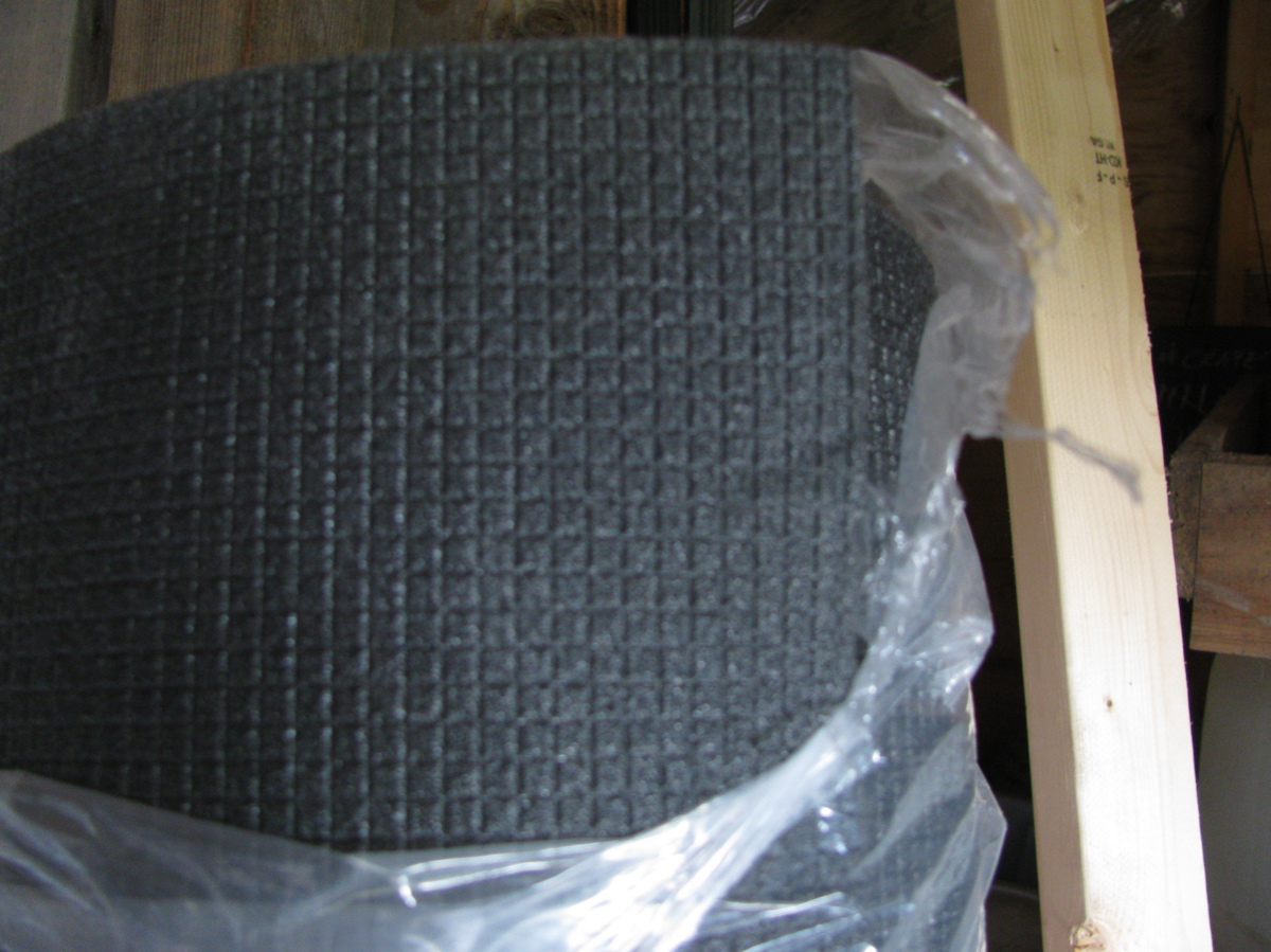
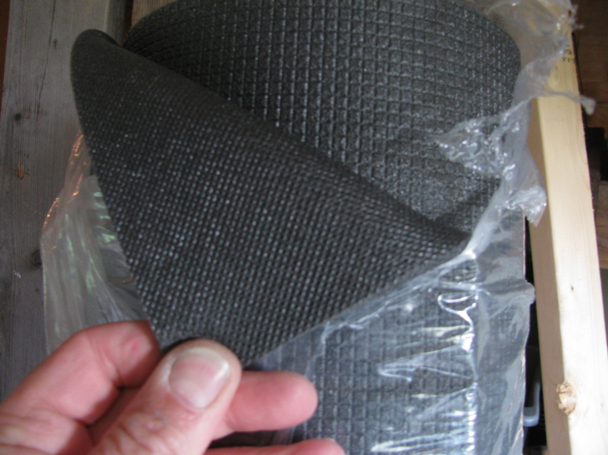
Posted by albell in vanagon, vanagon mods on June 6, 2011
I’m planning on gluing in this stuff on the ceiling of the pop top. It is about 3/8″ thick polyethylene closed cell foam. I’m still at a loss whether I should cover it after install, and with what. One guy on the samba insulated with refletrix then covered with fleece. No pictures of that and I can’t imagine how that would look.

Vanagon pop top work – final coat of paint
Posted by albell in vanagon, vanagon mods on June 6, 2011
Scuffed up the first coat and put on the second, both the luggage rack and main top. The dust and bugs were out today, and painting white on white in the sun was difficult, almost got snow blindness.


And a close up of the surface

I’ll let the paint harden for a few days before I do anything else with the top (seals, decals, hardware).
The obligatory hummingbird pics
Everyone does it, so I will to.


Vanagon pop top work – first coat on top
Posted by albell in vanagon, vanagon mods on June 5, 2011
Sanded the epoxy filled holes and scrapes and put on a first coat. Used a small foam roller and a brush to get into the curves. The paint went on pretty nicely but it a second coat is needed.


Vanagon pop top work
Posted by albell in vanagon, vanagon mods on June 4, 2011
Finally the weather around here has warmed up and looks stable enough to pull the pop top out of the garage and get around to painting it. I power washed it last fall, and did a bit of scuff sanding. I have this notion to insulate the ceiling with some 3/8″ closed cell polyethylene foam so I set about taking the fuzz off the ceiling. I used an orbital sander, which worked well. Then I thought I’d try some paint stripper (had a little bit hanging around), and that worked really well. I’m not concerned about getting all of the tan paint off the ceiling, just the fuzz and around the edges.


Then I used some thickened epoxy to fill some holes I had in the top. While the epoxy was curing I put a coat of paint on the luggage rack.


It’s not a great job and it does need a second coat, but it sure looks much better than it did on the old ’82 westy. Tomorrow I’ll get another coat on it and do the pop top.
Trip – Pavillion north on secondary roads
Courtney on the Vanagon list asked about the back roads north of Pavillion. I’ve travelled around that area a few times and here is a brief description of route and some pics. This is all form memory and google maps to jog my old mind, I apologise in advance for any mistakes.
You leave paved roads near Pavillion, up and west through the village.
The road climbs moderately until you get onto the bench lands. The road when I travelled on it was dusty and in places muddy. I can see how it could be quite messy and difficult in wet weather. Follow the meandering road as it heads roughly northward toward Jesmond. The Fraser will be to your left, down out of view, but the other side is visible. Then the road turns north east, away from the Fraser towards Kelly lake. There is a small campsite at the lake, Downing Prov. Park. Continue on the Jesmond road, through forest and you might come across a road branching off to the west. I think its the first road on the left. If you want take this road for a more scenic route.
That road goes through forest then down towards the Fraser, steep (25%) and narrow. Once out in the open the road turns north, following the Fraser. The Big Bar Creek cable ferry is down there. Spectacular view across the river, colourful eroded hills on the other side. Follow that road north along the Fraser, sage brush, cactus, dusty roads, rolling up and down until you get to Big Bar Creek.
We then turn north east up Big Bar Creek until we get back to Jesmond road. Turn left and drive north. You’ll get to an intersection, to the right (east) will take you to Little Big Bar lake (forestry campsite there, was nice until the trees cut down due to pine beetle kill) and further east is Big Bar Lake Prov. campsite. But we are heading northwest, on and on until we get to the Dog Creek/Canoe Creek road. Turn west and down that valley to the village of Canoe Creek.
Now we are back at the Fraser and I have some pics of just north of Canoe Creek.


And then you come to the suspension bridge across the Fraser.


If you cross the bridge you head northwest through the Gang Ranch and finally end up at the Williams lake to Bella Coola at around Lees Corner. We have taken this route to get to Nemiah Valley, a very worthwhile trip. But Courtney wanted to stay on the east side of the Fraser and head north to Dog Creek and further on to Alkali Lake. So don’t cross the bridge, drive north on the dusty road – and in places the dust is like talc – and you will get to both destinations.
Some more info on this area here, “Vanishing Jesmond” and here “Bicycling High Bar road…“
Vanagon syncro aux. back up light installed
Posted by albell in syncro, vanagon, vanagon mods on June 1, 2011
I gave up on making an adaptor for the chrome light housing and decided instead to make one for a rubber housing, here it is.


Made of black polyethylene, kinda clunky looking. Jony Ive does not live here. It does seem to work though.


I led the power and ground wires through one of the holes in the rear valence, up over and well away from the muffler, and through a grommeted hole in the heat shield. I do wish there was a better route. I used one of those black plastic electrical box to house the relay.

I used wire I had lying around, not conforming very well to any colour code. I did use a little bus, power is on the right, and ground on the left. I mounted the box onto the plastic “bulkhead” that the air intake snorkel connects to on the right hand side of the engine compartment. I tapped into the black/blue power wire feeding the right hand side back up light to provide the signal power for the relay.

I also put in an old back up beeper I had on my ’82 westy. I was a good thing to have when my son was young and I got used to it, so now it’s on the syncro, just lying in front of right hand side tail lights.

I took power from the alternator stud – NOTE – I have not installed in inline fuse on this feed line yet, one DOES need to be installed. I led a ground to one of the alternator housing screws.

Gack, I need to buy black cable ties. Tested, and works (beeper too).

