Archive for July, 2010

Sway bar drop link sleeve modification
Posted by albell in metalworking, syncro specific repairs on July 22, 2010
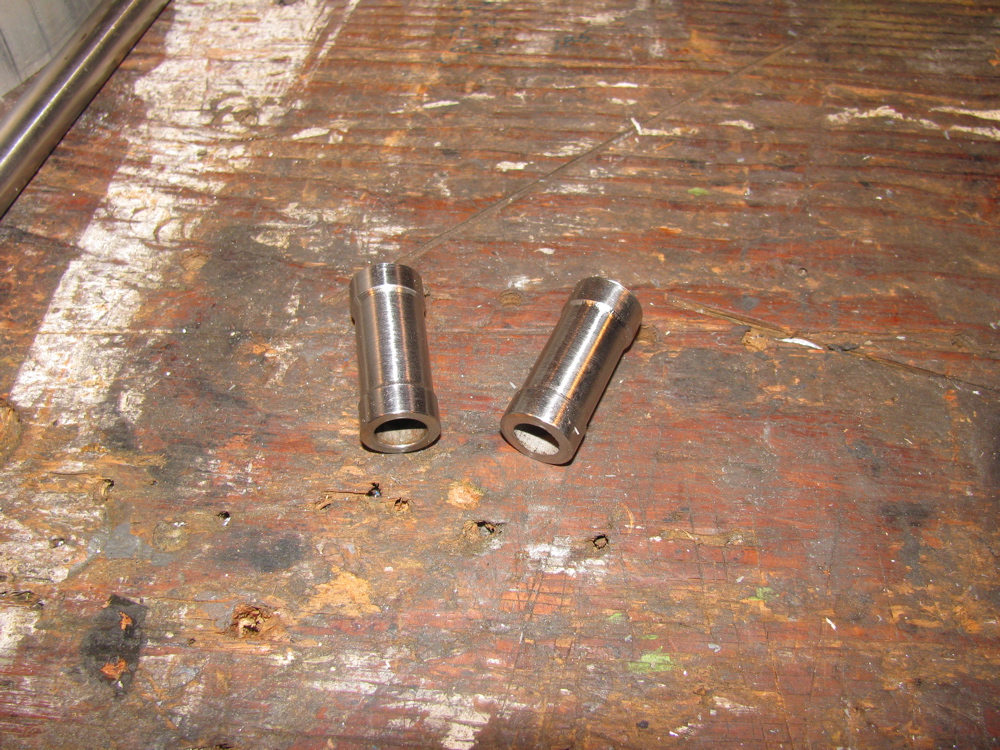
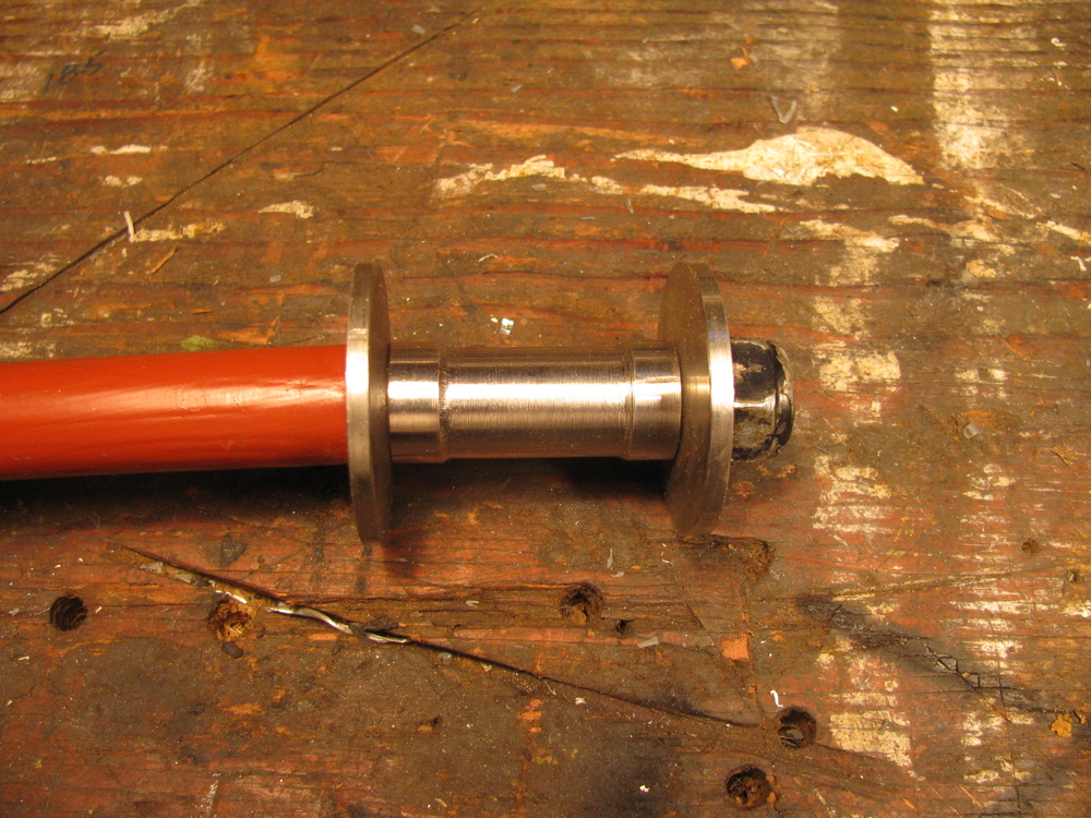
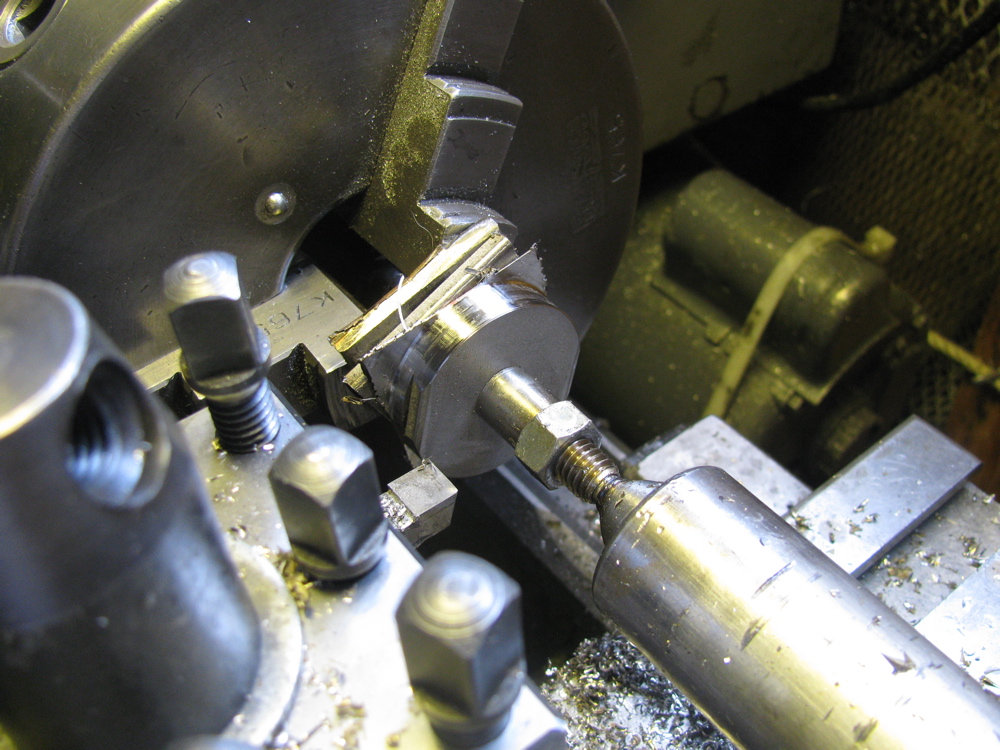
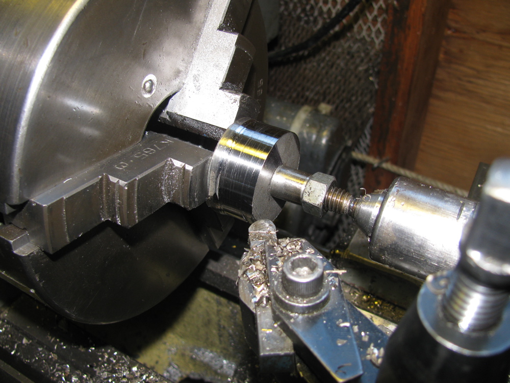
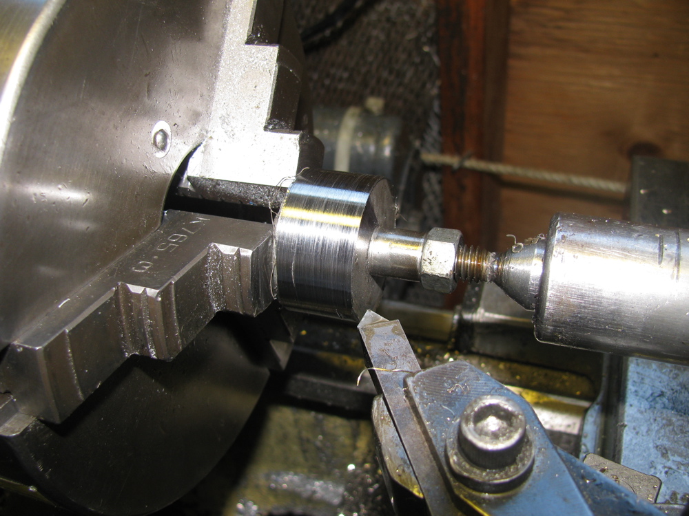
Fellow syncro owner Doug M. pointed out that I had made the drop link sleeves too tight a fit in the radius arm hole and that would limit the amount of movement needed in the rubber bushing-drop link connection. He is right that the joint there needs some degree of movement, limited and moderated by the rubber bushings. So to correct this I lathed down the centre sections of the sleeves, from 0.650″ to 0.600″. I had to make a quick and dirty mandrel to mount the short sleeves on the lathe. The length of the narrow section was judged by eye so consequently the 2 sleeves are slightly different.


Back to Cyclekart
Posted by albell in cyclekart, metalworking on July 18, 2010
Dug out the bits I have already made and re-started the project. I can’t find suitable leaf springs for front suspension yet, I’m not willing to mail order horse buggy seat springs just yet. Will keep looking and also explore using the spring/shock combo from a Motobecane moped (2 mopeds were the source of wheels for project).
Some useful links about cyclekarts:
Steve C’s blog and cyclekart build
Pretty darn good cyclekart site
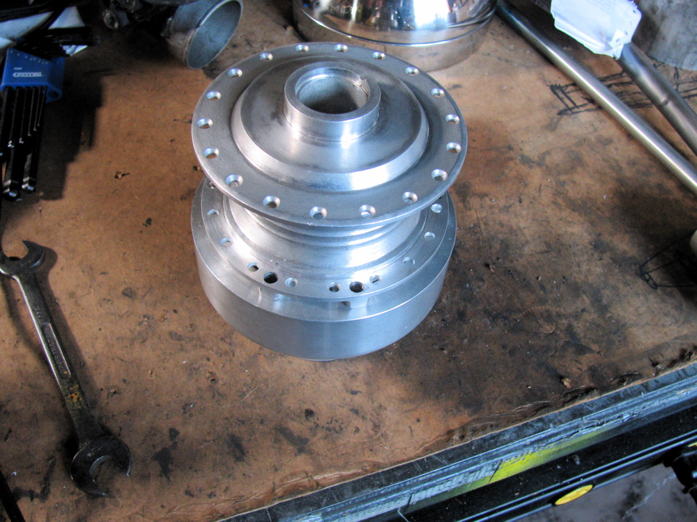
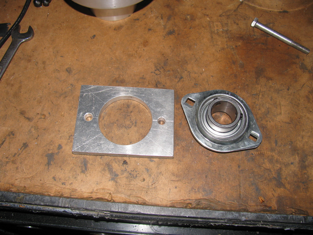
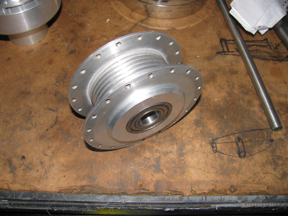
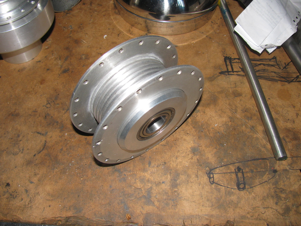
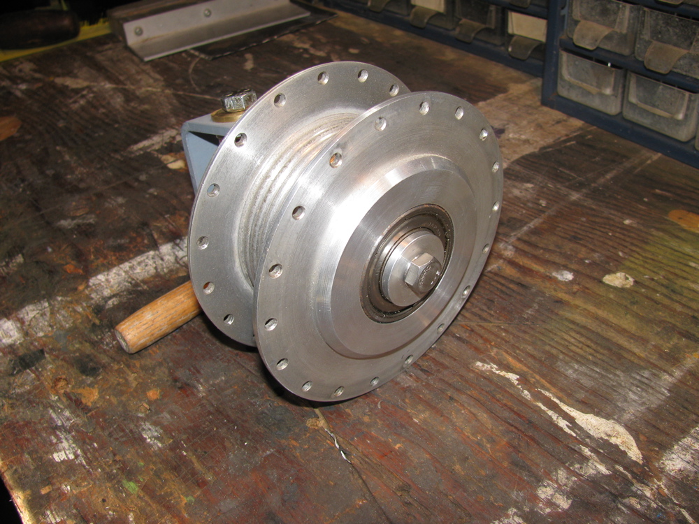
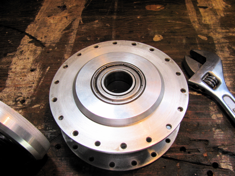
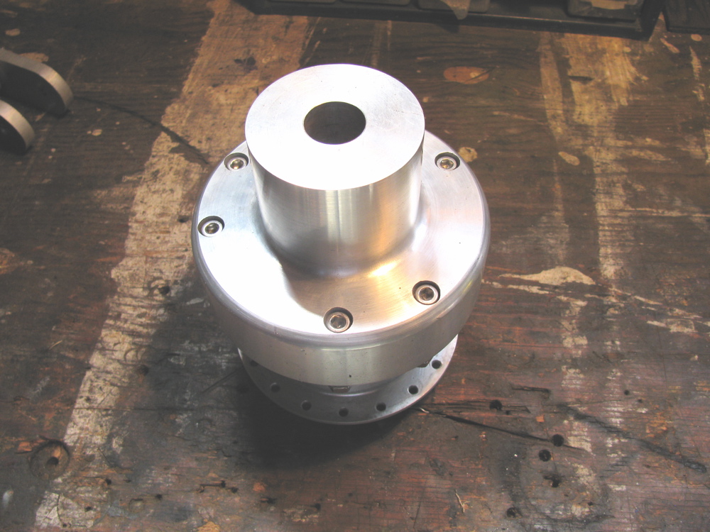
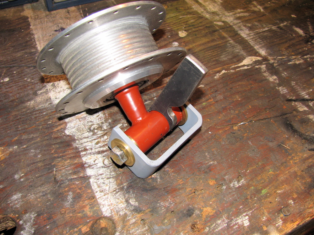
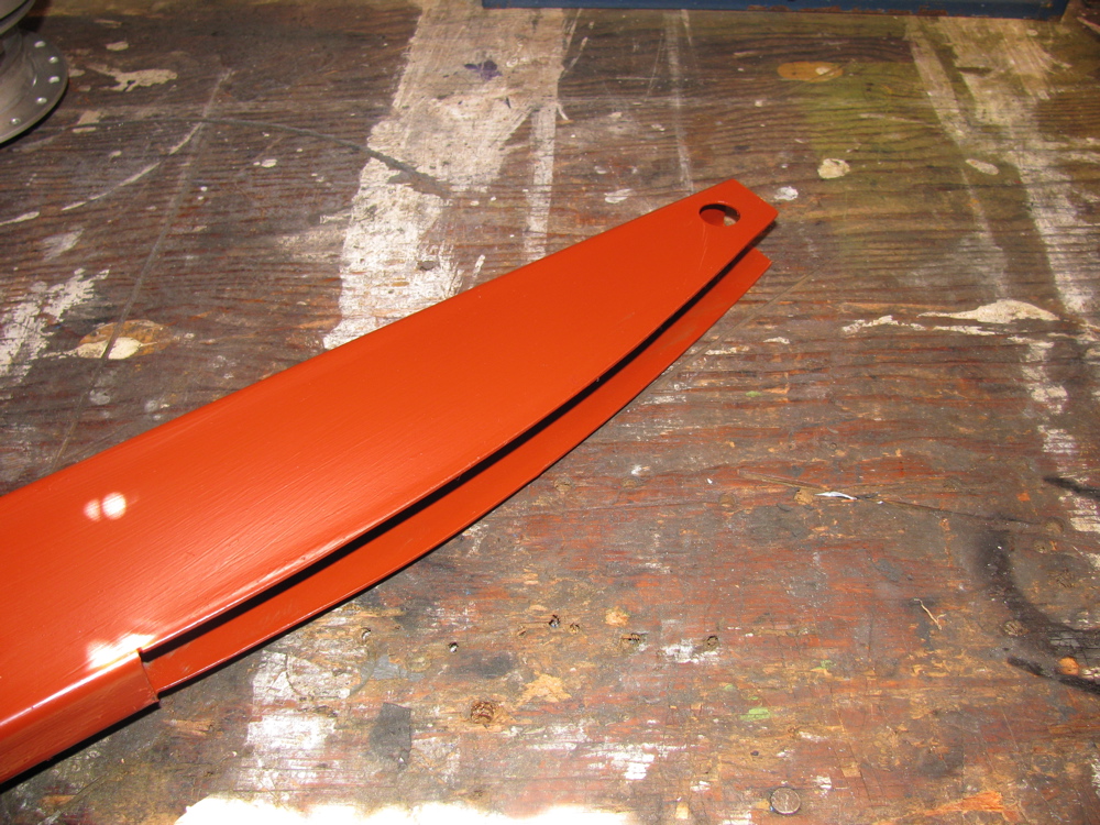
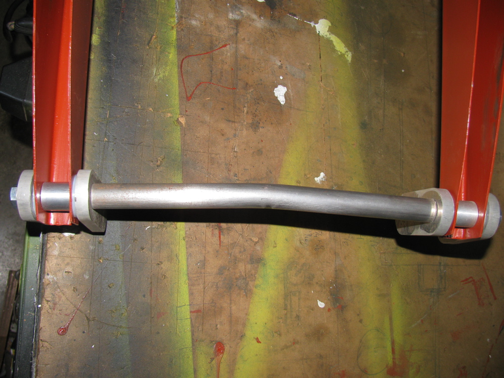
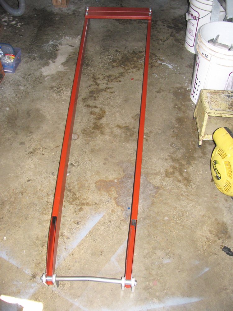
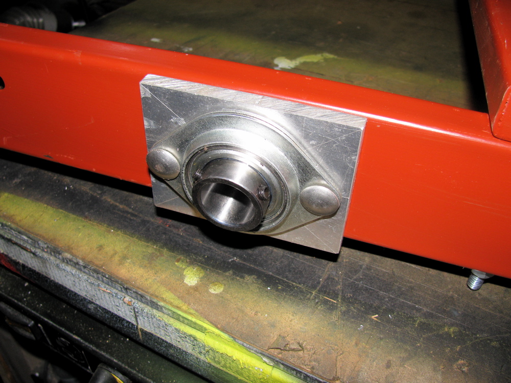
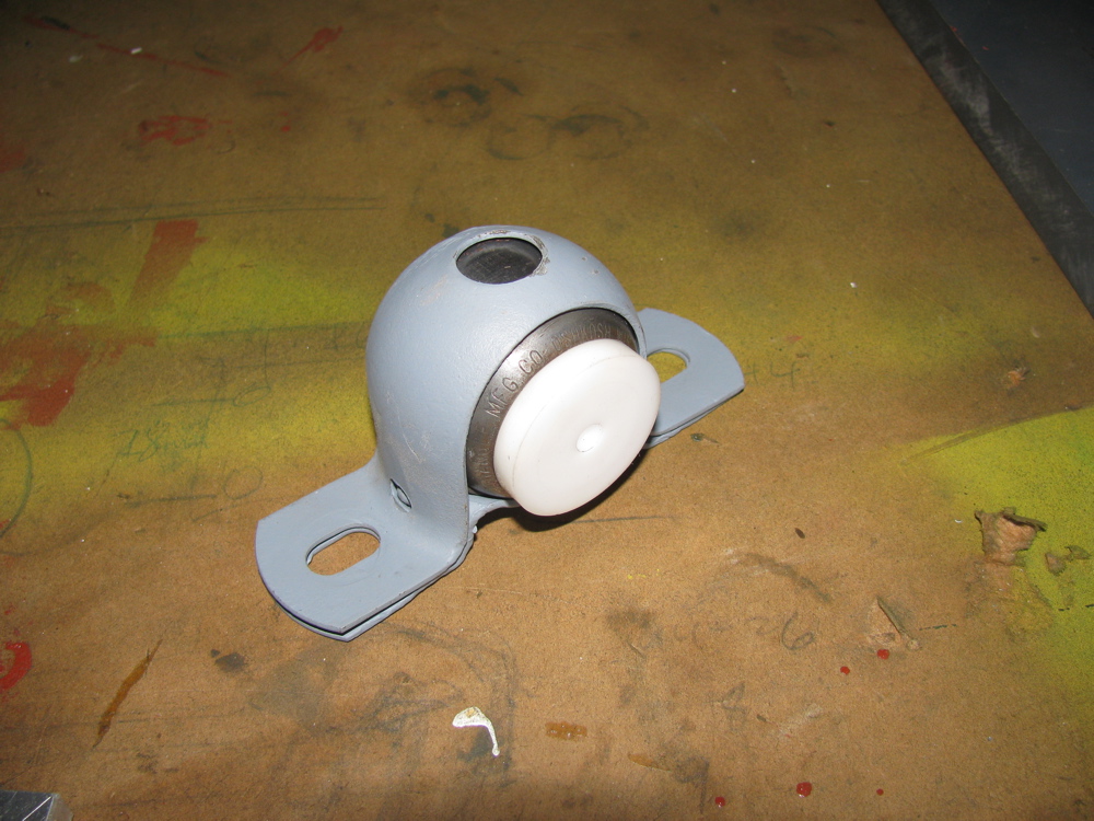
Below is gallery of the parts I have made so far for my cyclekart.
Oh a couple of notes: I have machined the moped hubs and made adapters out of aluminium, both for front and rear wheels. Rear hub adapter not keyed to axle yet, and the freewheeling rear hub adapter not shown. The metal cross bar/rod shown is an experiment, I am not sure if I will go with it in final car. Its bent to allow machined shoulders to lie flat on frame sides. But it really didn’t turn out the way I imagined. The white plastic bit in grey metal holder is potential steering rod bearing.


Homemade trouble light
Posted by albell in vanagon mods on July 12, 2010
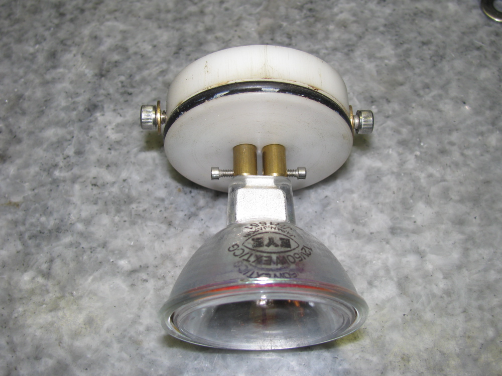
About 10 years ago, Dave the machinist in the UVic physics dept. made this trouble light for me. It uses a 50 watt glass shielded 12 volt lamp, copper tubing, some hardware, O-rings and polyethylene. I connected it to a length of reclaimed cord and a connector that fit the “silver socket” type socket. The plug and socket was salvaged from an agricultural dust mask. I wired the socket in the engine bay of my ’82 westy.


Canoe dollies
Posted by albell in greenwood canoe on July 12, 2010
For Mike’s edification…
Pic of my first canoe cart. Made in a rush before a trip in (summer 2000) from scrap white oak and wheels borrowed from my Rubbermaid wheelbarrow. Held together by galvanized lag bolts and comes apart easily for storage. The large wheels really make a difference in how it takes bumps.

Next are pics of the summer of 2003 and 2004 canoe cart, (AKA MkIV). Constructed from aluminium tubing and aluminium “Kee-Klamps”. Wheels are plastic spoked and rimmed, pneumatic tires, quick release mounts. It disassembles completely. Support strut flips sideways up out of way.


In use between Elkin and Vedan Lakes, in the W. Chilcotin, B.C. Canada, summer of 2004. It is very easy to roll, blanced slightly stern heavy so that bow is pushing up slightly on one’s hand. My son can get a free ride on the 1.5 km trip back to camp (we had just made a trip between the two lakes via the little connecting stream).

Prop shaft vibes – maybe solved?
Posted by albell in syncro specific repairs on July 11, 2010
Last week I had some success in reducing prop shaft vibrations. If you read this blog you know I have been chasing this problem up one tree and down the other. One thing to finally clear up before I go on, is the question of the presence or not of a plastic spacer on the front mount of the front diff. I think I can conclude, for sure, that on my diff at least, there is no plastic spacer(s). The hole in the diff mounting ear is too small in diameter to allow the spacers found on the other mounts to fit.

Here is a pic of one rubber mount (they are installed in pairs), a stock plastic spacer, and a home made spacer when I was still thinking my van was missing them.

As is, this still leaves the front diff flange pointing down at 3.7 degrees which is not close to the transmission flange angle of 4.6 degrees. By the book, these angles should be within 0.5 degrees. When I say by the book, I am not referring to the Bentley manual which has no information on this subject. Instead, I get this fact from a drive shaft makers publication, here;
I don’t like the fact that the transmission angles down that much, but I can’t really see how to raise front of trans. easily, and besides , it looks like there is little room above transmission to do this.
Out of frustration more than anything else, I decided to try adding weight to the drive shaft, thinking that perhaps the shaft was out of balance (I had replaced U joints, and who knows, it may have been out of balance before I got the van). I attached a gear clamp 3 ” from the front end of the shaft, right where there is a factory weight. test drive revealed no change. I rotated clamp 90 degrees and, by god, test drive showed a big reduction in vibrations, in fact the vibrations were almost gone.
Next step is to refine position and try additional weight. Local drive line repair shop does not have mandrels to do syncro shafts, but the tech. said he would be willing to make mandrels if supplied with measurements. I may be on to something.
Sway bar drop link refurb.
Posted by albell in metalworking, syncro specific repairs on July 11, 2010
Between watching the Big Game and other things, I made some metal sleeves and convex washers for my sway bar drop links. The sway bar is off the van due to a broken link which I repaired earlier . A broken drop link seems to be a common thing, and its due in part to the steel sleeve inside the rubber bushings trapping water and rusting. This can cause the drop link itself to rust and also when the sleeve rusts out may allow the drop link to move more than it should, stressing it. I fixed the link by facing off the broken stub, then drilling into the link and tapping for a 10 X 1.5 mm bolt. The bolt was screwed in and tack welded. The bolt head was then removed and threaded portion cut to size. The picture shows the repaired link and beside an original. The stainless tubing was just an early try at finding a sleeve.

And just because I thought it a neat idea, I made bushings out of old skate board wheels.

I guess a diagram is needed showing all of the parts…

I needed to make new washers and sleeves (spacer tubes in diagram). The washers are dished and made of steel. The spacer tube is thick walled steel. I am not sure if the washers are still available, and I really wonder if the dishing is needed (allows more “wobble” in the drop link-rubber bushing connection).
First the sleeves. Some schedule 80 stainless tubing was found at the local Metal Supermarket (I took drop link along for trial fit). I don’t know what the listed size of this stuff is, but a casual measure has it at 0.675″ OD and 0.42″ ID. The tubing was cut into 40 mm lengths (well, that’s what the rusty old stock sleeve was). I nipped out to test fitment in the hole in radius arm and found it was too large in diameter. I had to turn the sleeves down to 0.650″ diameter for an easy fit.
At this point I should mention that I am not a machinist, nor am I a talented amateur, so forgive any bad technique shown and the quality of the finished work. Now onto the washers. I had some stainless bar in the workshop, 1.5″ wide (not quite as wide as the stock washer diameter, you’ll see evidence of that in the pics), 0.187″ thick and I cut it up into rough bits, drilled holes in them and mounted them all on a really dodgy mandrel/spud/spigot/whatever on the lathe. Not the best technique, had to go slow and light to avoid hammering. Of course it would have been better if I had made them into hexagons at least before turning. Anyhow, I made the stack round. Then I mounted them individually on the mandrel and gave them a slight crown. Took a while but I still have my eyesight and digits.
The sturdy new washers are thicker than the old washers and this may be a problem when it comes to installing with the rubber mounts. If needed, I’ll shorten the sleeves by a couple of millimetres or so. Oh a couple of points… I was working on the “other side” with the lathe in reverse when making the washers convex. And you can see evidence in the finished washers that my stock was not quite wide enough, not big deal, just aesthetically crap.
Oh, one more thing, I ground off the little collar seen around hole in washer after I took the pics. The collar was left over from the lathe work. When the washers and sleeve are assembled on the drop link, and the nut is tightened, it all feels pretty solid and strong. I still would like the sleeve to be a snugger fit on the drop link, but probably is just fine as is.
I need to find some rubber bushings now. You can buy stock ones, but criminy, they cost $10 a pop!
Edit: see here for sleeve modification


PS. For images and prices of the “real” parts, check this page from Van Cafe
