Archive for February, 2013
Vanagon – led lighting the glove compartment
Posted by albell in vanagon, vanagon mods on February 24, 2013
I was in an unsettled mood today, my plans to help good friend Simon add some shims to his syncro were scuttled by unforeseen events. Spent some time with my falling apart dash cluster, trying out a new UV led, but that made me feel worse – the cluster foil is in such bad state that I fear the next time I go in there I’ll really be forced to do a hardwire. So I looked around for an outlet for my angst and I fell upon the 10″ bit of led strip left over from the interior light install shown in last post (on the kitchen side the 2m strip had to be trimmed to fit).
I had this idea to wire it in parallel with the small light above the glove compartment and placed so it would light up said compartment. And I didn’t want to dick around and fuss with the install, so what follows could have been done better.
Look up the Wikipedia entry for glove compartment. I draw your attention to the last paragraph, more proof that the Vanagon was a car ahead of its time.
Most led strips can be cut on the indicated lines (drawn on face of strip), at the cut area there are soldering points. I soldered a couple of wires to those points (nice tinned, teflon insulated wires).

Then some heat shrink.

Polarity is important, that’s why I have both wires the same colour . There are tiny +/- markings on strip, but you can confirm with 12 V power source (I’m fortunate to have an adjustable DC power supply. It is very handy for this sort of dicking around). The positive wire was soldered to the long contact strip on the little light that mounts above glove compartment (what the heck is that light called anyway – Courtesy light? Vanity light? it’s a Map light according to BenT). The negative wire was soldered to the other contact strip. Yes, soldered to the strips. As I said, I wasn’t feeling like doing it kosher.

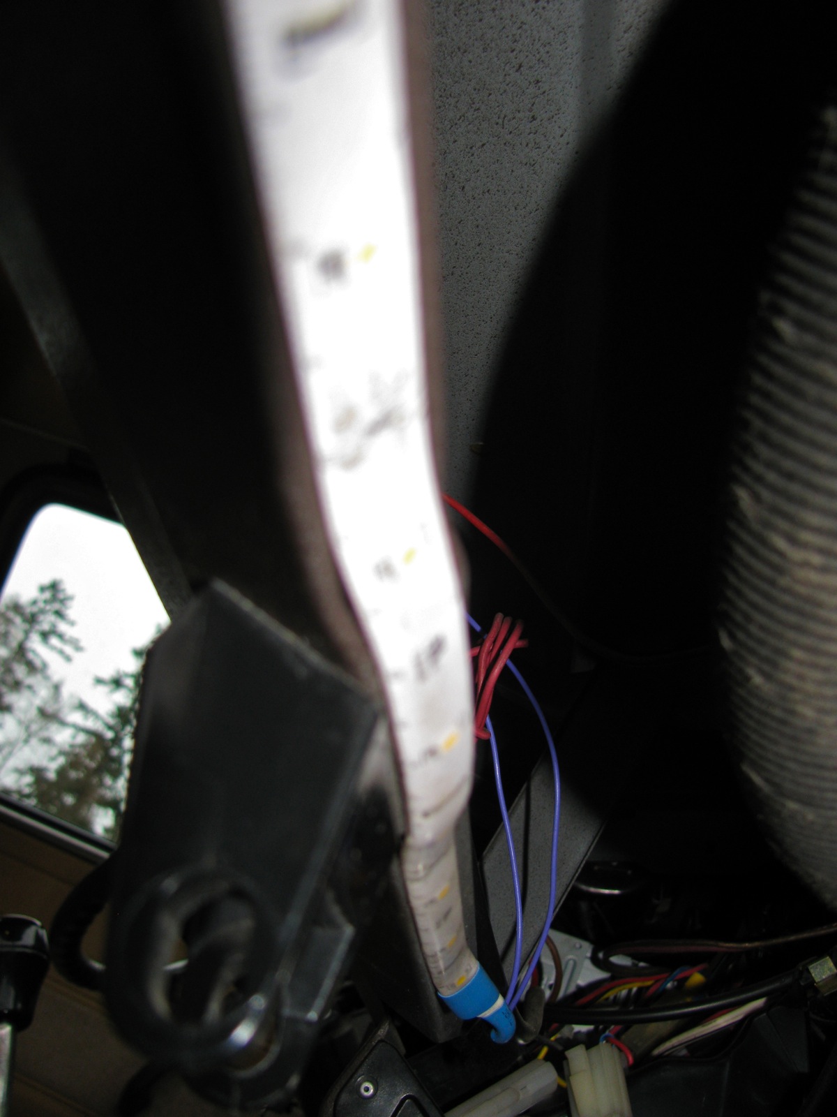
The strip and wires were fed through the light opening and the light popped in after. The strip has self adhesive backing, and I stuck the strip up under here (sorry about focus).
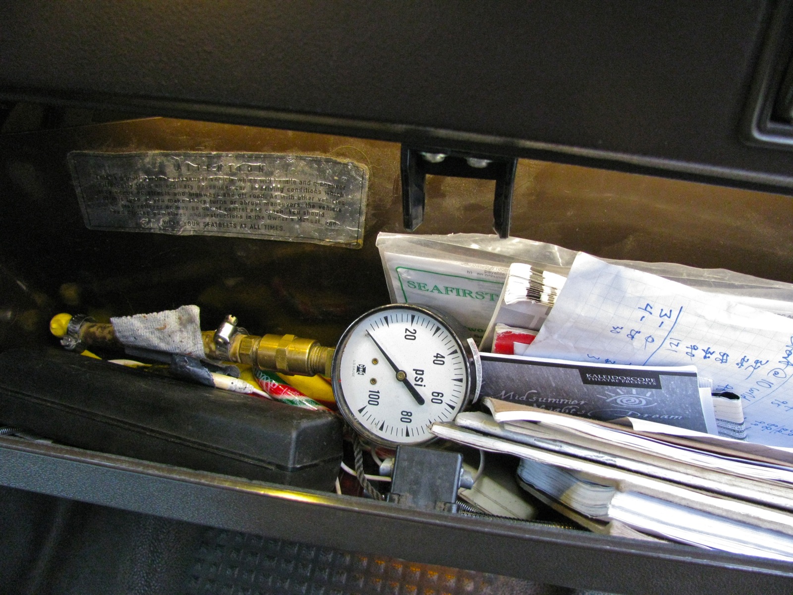
And how does it work? Some daylight pics to show.
Light off.

Light on.
Well what did you expect? Fireworks?
🙂
Just to be clear, the led strip is now switched on and off via the “courtesy light” or whatever you call that little light above the glove compartment. (BenT: It’s a map light, you dolt)
Vanagon – interior lighting with led
Posted by albell in vanagon, vanagon mods on February 23, 2013
I’ve been wanting to have some led strip lighting in the van for a while but never got around to ordering any online. But a few weeks ago I found some led strips at local hardware store and even being on sale they were pricey ($43 each), but I fell for them. You can do much better price-wise online.
The strips are 2 m long each, with 60 smd leds per strip. That’s a good led density for this application. Calling leds “warm white” is so subjective, a little better descriptor is colour temperature, and these were listed as 3500 K correction, 3000 K. The strips came with a small inline transformer to change 110V AC to 12 V DC. We don’t need that for the van, but we do need some sort of switch. I decided on an inline dimmer/controller from Superbrightleds.com, this one. I ordered 2, one for each strip. When they arrived I realized that perhaps an inline dimmer is not the best way to go, would be better to have a wall mount. Time for some metal butchery. The same old thing with me, going the long way around.
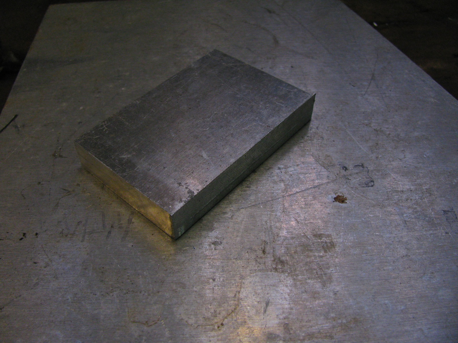
A bit of 1/2″ aluminum.
I really just eyeballed the milling (used the wee milling head for my lathe).
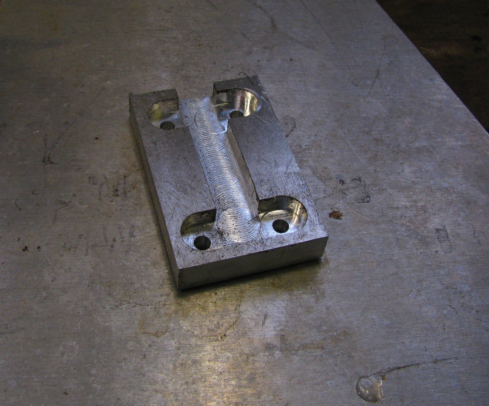
Then a half hearted clean up. I need to get a better countersinks, see the chatter marks in the holes, especially the mounting screws?

And the dimmers added.
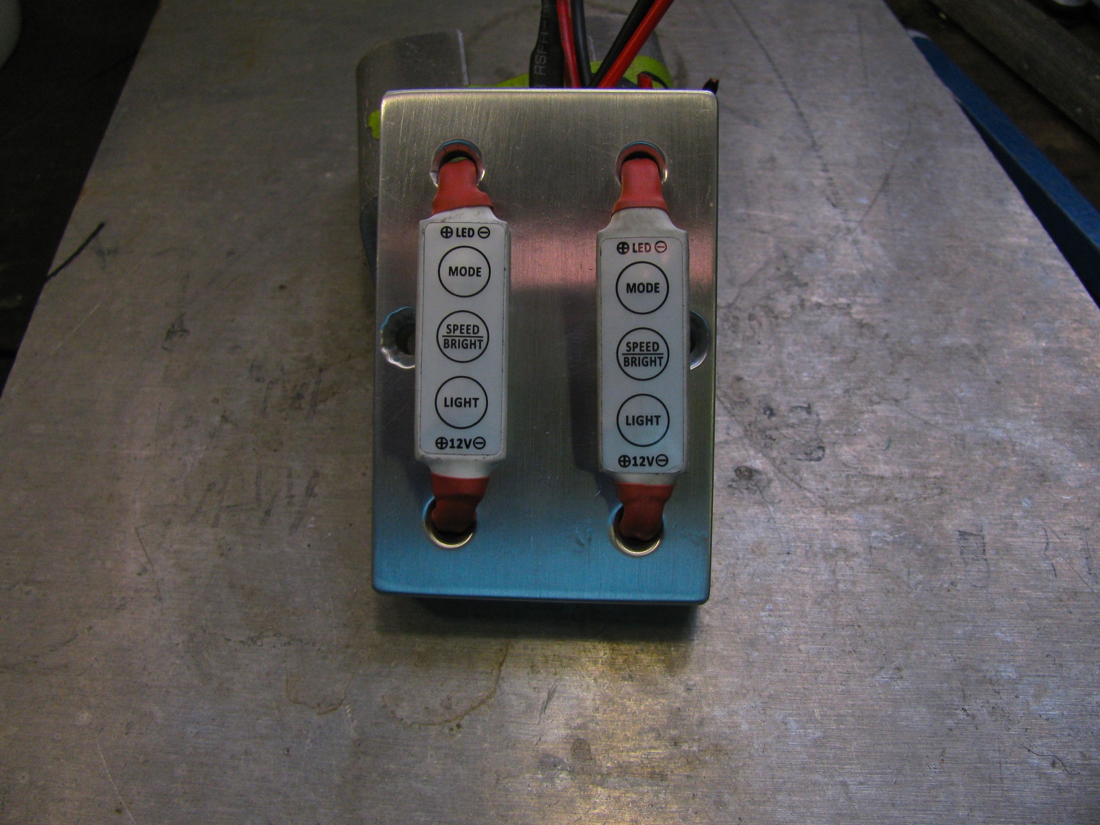
The milled slots use now clear. Can I draw your attention to the black heatshrink on the ends of 2 pairs of wires? I forgot to remove one of them, grr.
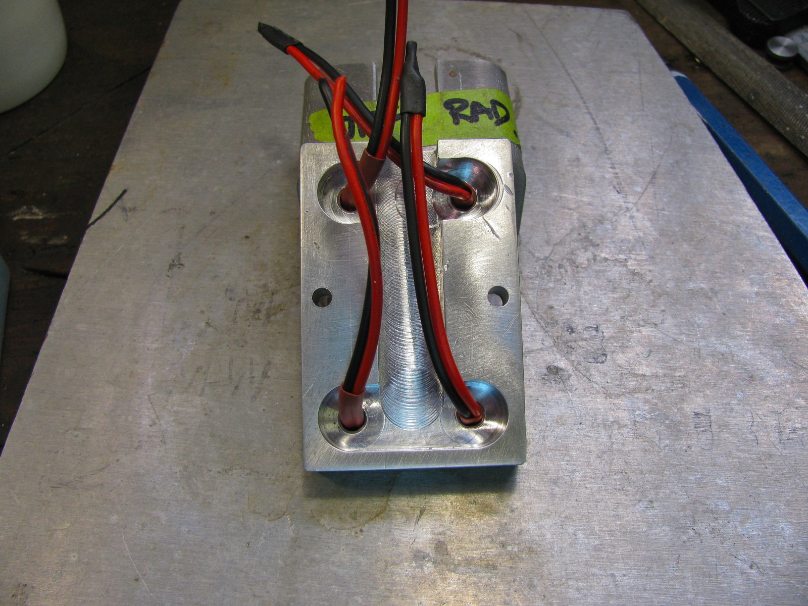
I secured the wires to some extent with some Goop. The heat shrink job was redone a couple of times after this, you’ll find out why.

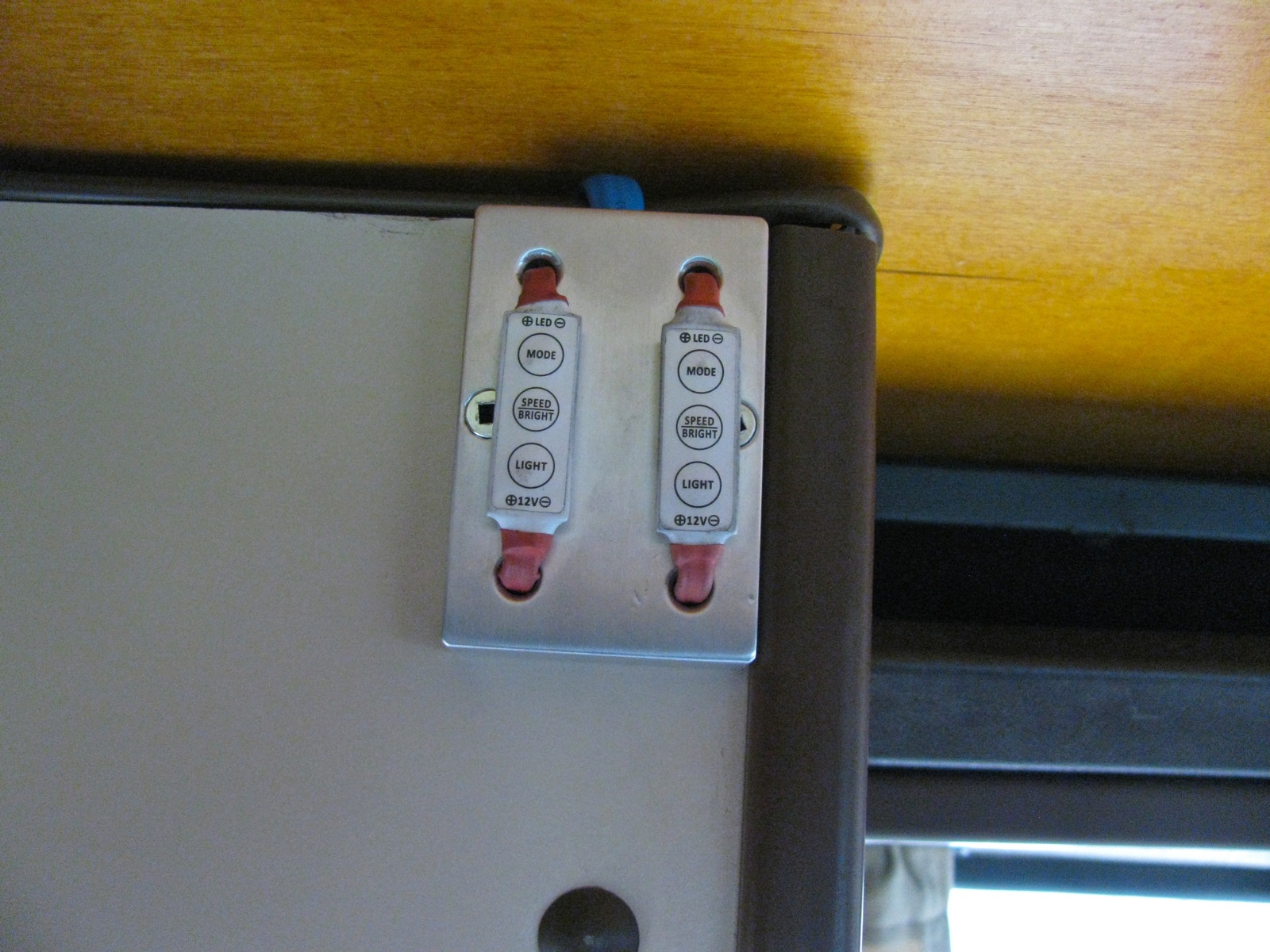
And installed on top front inside corner of the wardrobe. I figured I could reach the dimmers when lying in the lower bunk.
The leds strips were installed in two places: one on the underside of the kitchen trough so that it pointed straight down. The other on the angles face of the slider door valence. The latter shines in and down. So I wired the strips to the dimmer and during the process forgot about one of the heat shrunk wire ends, and I shorted one dimmer which let out a little magic smoke. Stupid mistake eh? I left the broken dimmer in place and re-rewired things so that the remaining dimmer controlled both strips. Troubleshooting this screw up resulted in re-doing a lot of connections, sigh.
This pic makes the slider door side strip seem brighter and more glaring than it actually is.
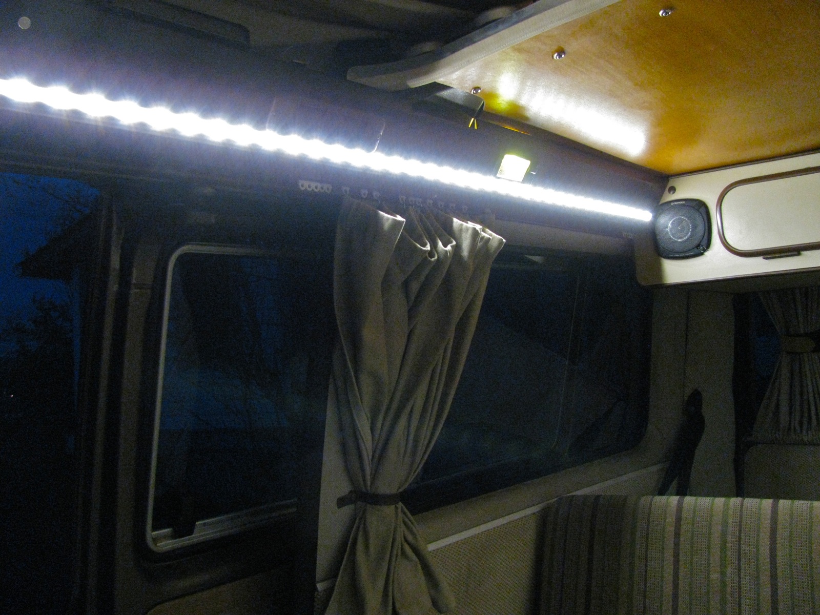
The kitchen side strip has no real glare, I’m guessing the beam angle of the leds is about 120 degrees.

I’m very happy with the amount and quality of the light these strips make. I’d like to add more, and maybe even some RGB strips and a colour mixer.
Addendum : I forgot to mention how much power the lights draw – if I recall correctly it is around 4.8 W per strip. I know nothing of how PMW controllers work, ie how much power is used by controller and strip when light is dimmed down low.
Another addendum:
I did some measurements with my installed Doc Wattson. Measuring current flowing from my aux battery.
first, van as is:
leds off, 1W, 85mA
leds full on, 9W, 750mA
leds dimmed lowest setting, 1.7W, 140mA
Radio face plate off:
led lights off, <0.1W, <10mA
For interesting comparison, kitchen water level/battery meter panel on, led lights off, between 0.2 and 0.3W, between 20 and 30mA.
So the led dimmer control draws a little power even when off, but it is less than the “switched on” kitchen indicator panel.
So the led strips, both sides combined, only draw 140mA power at lowest brightness. And that low setting is pretty good for a standby/casual use light.
Vanagon – dash/glove compartment light minor mod
Posted by albell in vanagon, vanagon mods on February 20, 2013
Those of you that have the little light above the glove compartment know how easy it is to ground the hot part of the light against the dashboard metal when you remove the light. I have lost count of the number of fuses I have lost that way. Oh sure I hear you say, why not disconnect the battery before removing the light? Well, yes, of course.
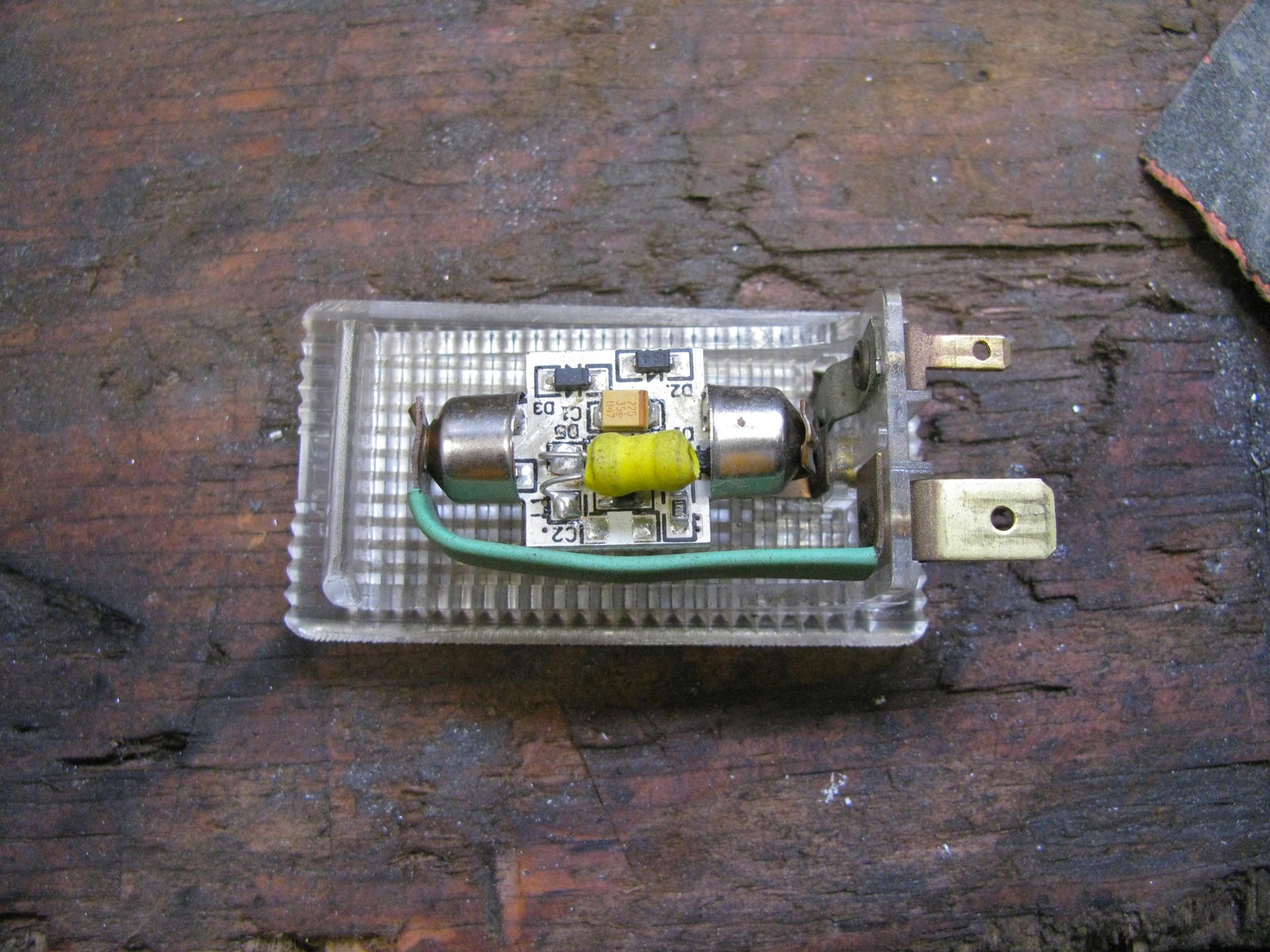
But, you can do something else. Slip a bit of heat shrink tubing over the flat metal inside the light. Shrink it up and your good to go. Here is a pic (I have a LED festoon replacement light in there). The light green is the heat shrink over the metal strip.
Vanagon – syncro front outer cv joint protection plate
Posted by albell in syncro, vanagon, vanagon mods on February 16, 2013
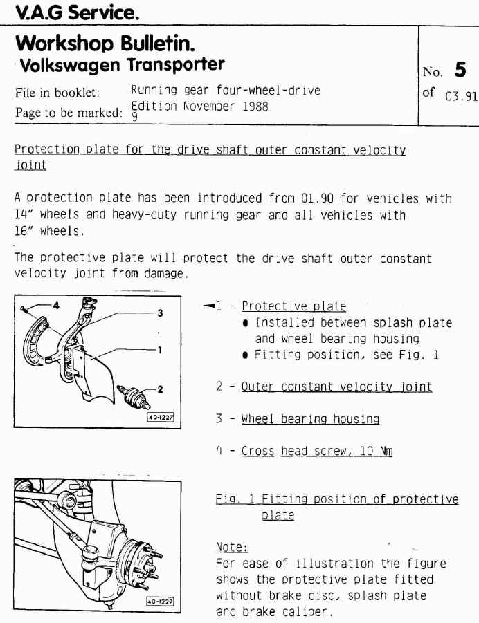
The story goes that VW introduced these protectors in 1990 for 14″ syncros with the rough road package, and on all 16″ syncros. Here is the English language bulletin.
I wanted some. I worry about logging road debris catching on the front outer cv boot, and that boot is a pain to replace. You can buy them, one good source is Burley Motorsports, but seeing as there are plans for them on the internetubes I thought I’s have a go at making a set.
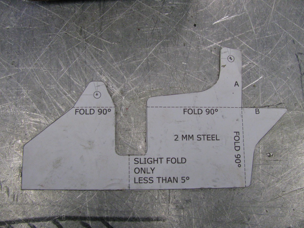
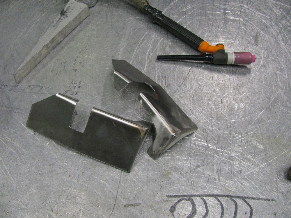
Here are the pdf’s of the plans I used: CV_protectors_bracket, CV_protectors_Rubber. I scrounged all of the material used, so my version differs slightly from the plans. First up are the metal parts. I had some scrap 14 gage stainless which is not quite as thick as speccified ( 1.6 mm vs 2.0 mm), and I glued a print-out of the plans to the metal and cut to shape.
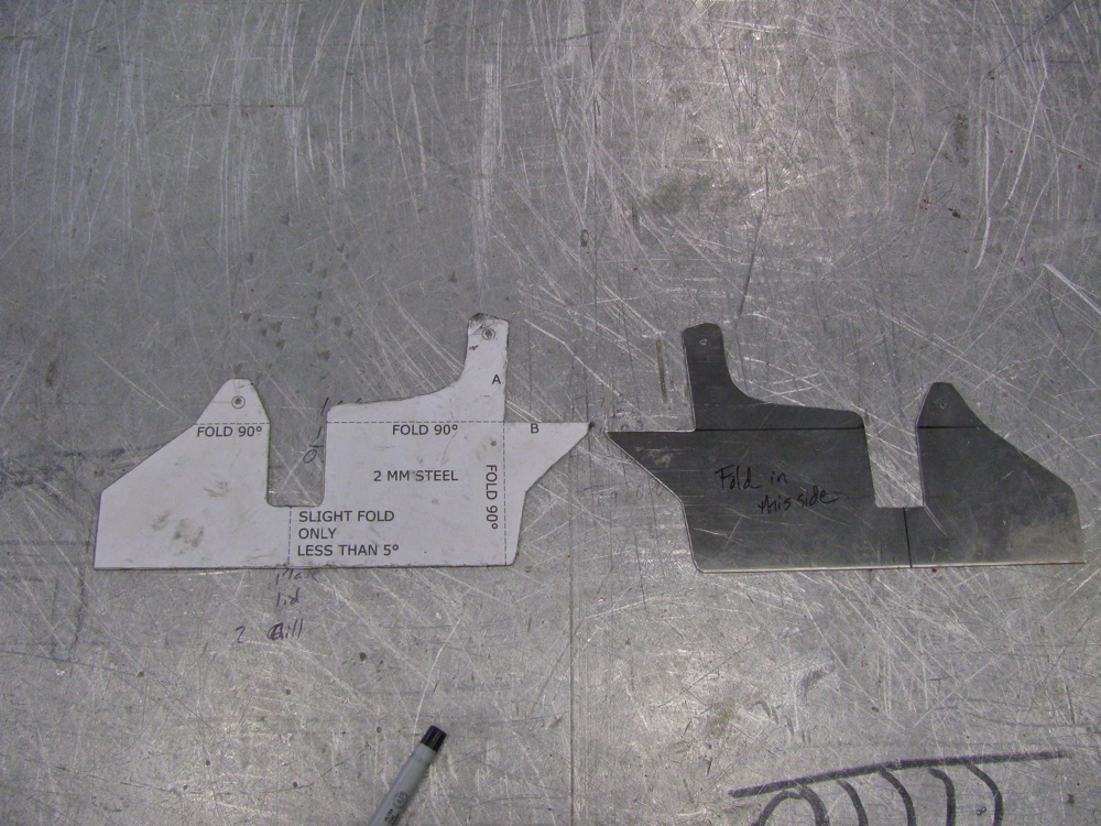
I bent the parts in a vise (that accounts for the less than crisp bends), then I made a hack-job of the tig welding. I need new glasses, well that is my current excuse for my poor welding.
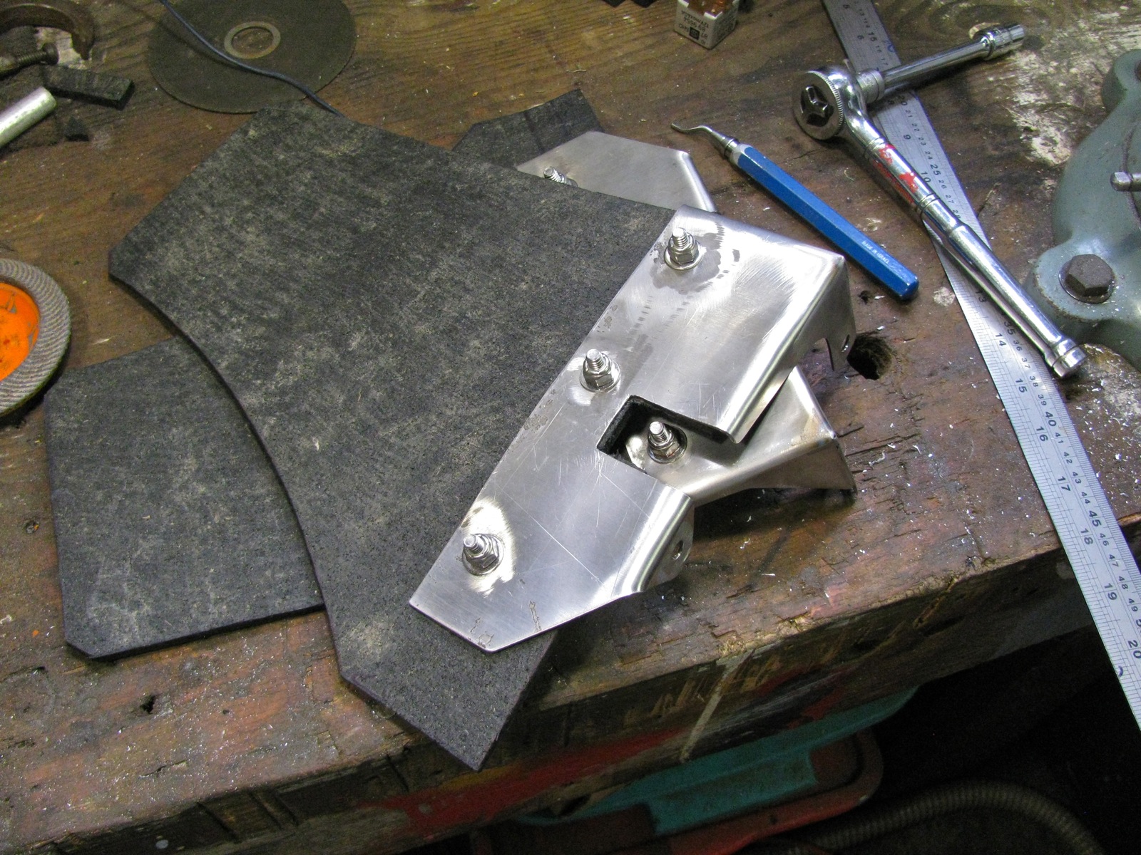
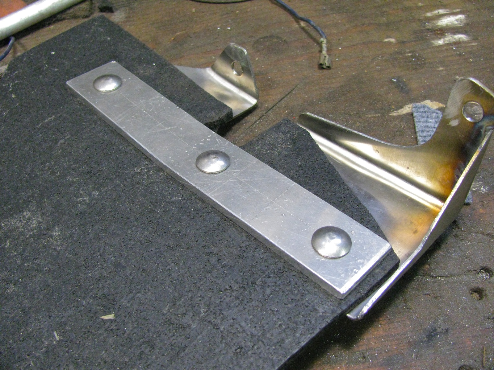
Next was the hunt for rubber. You’d think it would be easy to find some 1/4″ thick, fabric reinforced conveyor belting, wouldn’t you? I spent an hour looking then I used some 1/4″ rubber sheeting that my neighbour had. It is not the best stuff, it is like thin horse stall matting. You know, crumbled tires pressed together. I can always replace the rubber when I find the belting. Ok, enough mumbling, I cut the rubber and I cut some 1/8″ 6061 aluminum for the backing strip. I used 1/4″ – 20 ss carriage bolts (the square part of the bolt shank will dig into a 5/16″ hole drilled in the backing plate) and nylock nuts to hold all the parts together. Well all but one, I ran out of nylocks and had to use a split washer and plain nut.
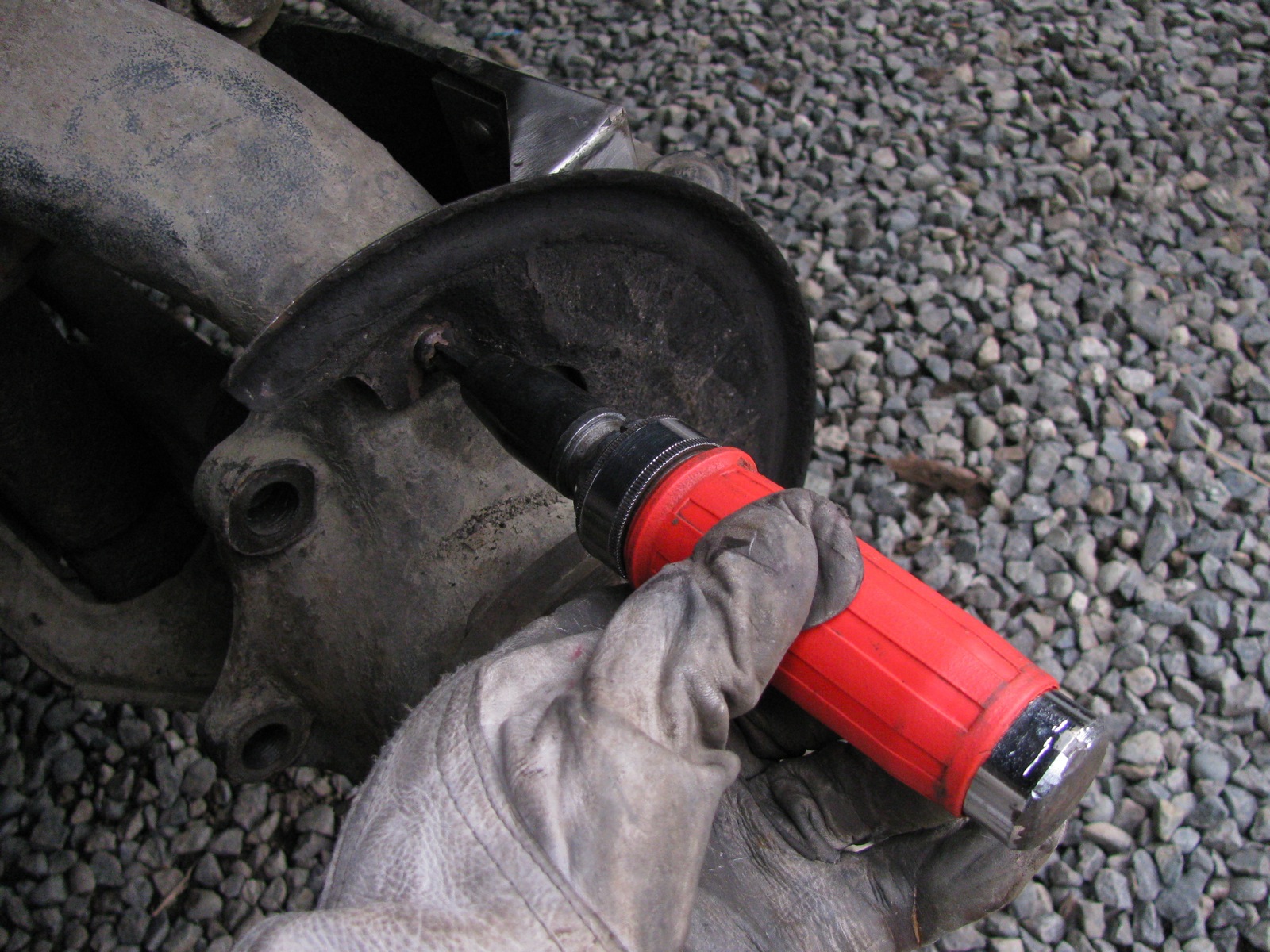
Okee-dokee, out to the van and installation. It is a bit of a pain, you have to remove the brake calipers and rotor to get to the backing plate. The same old but important safety warnings apply – van securely supported etc.
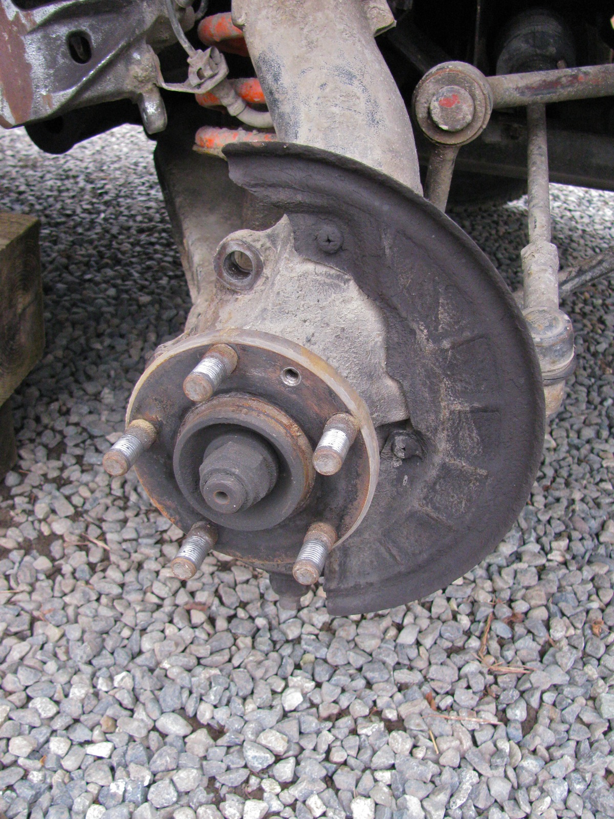
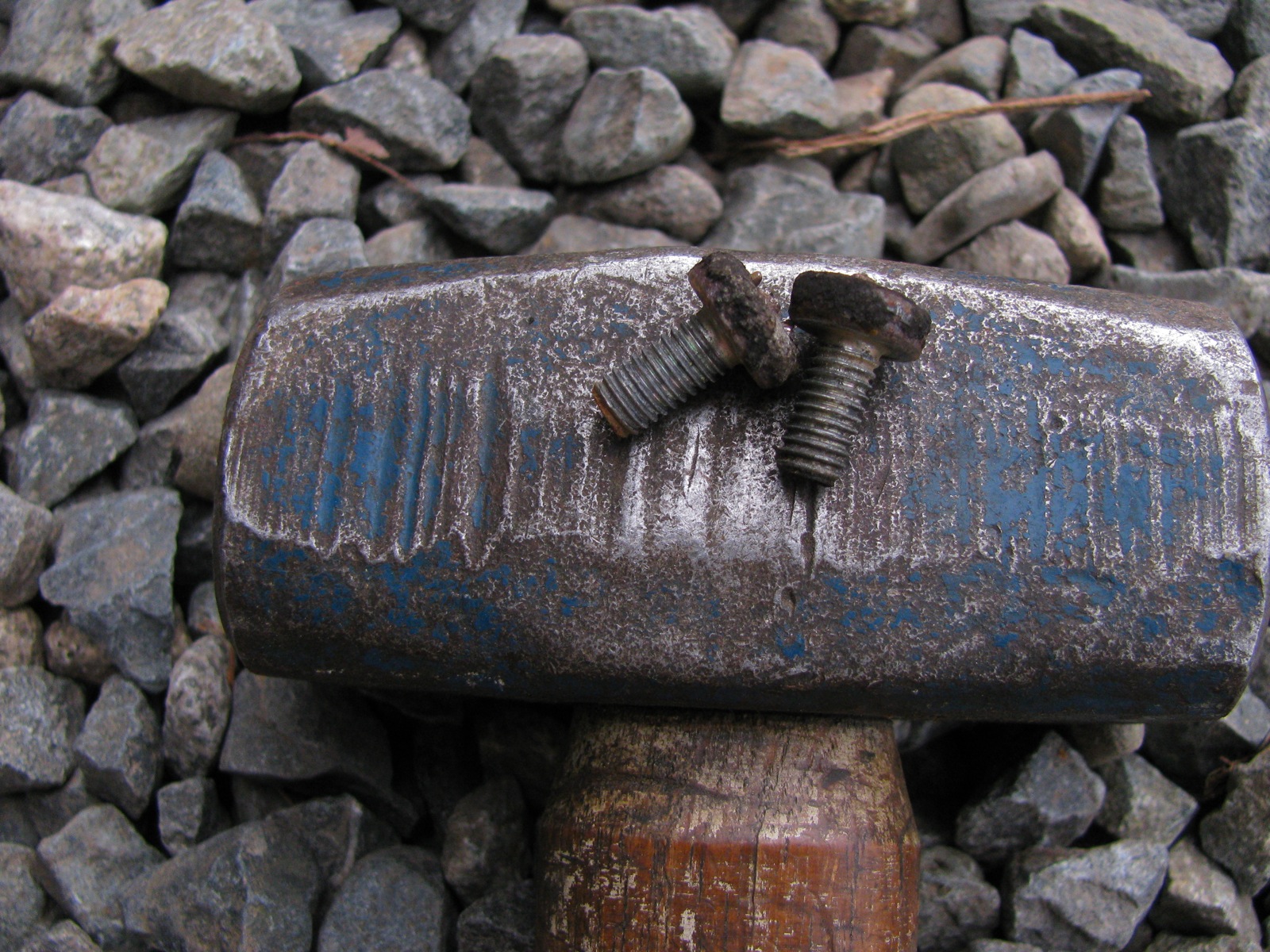
Two phillips headed screws holds the splash to the steering upright (or bearing housing, as VW calls it). They were fekkin tight, I doubt they had ever been removed. I had to use an impact driver, but even so I still managed to bugger up the screw heads a tad. I have said this before about my van, despite the ugly areas of body rust I have, all the fastenings (despite how tight they have been) are not rusted in.
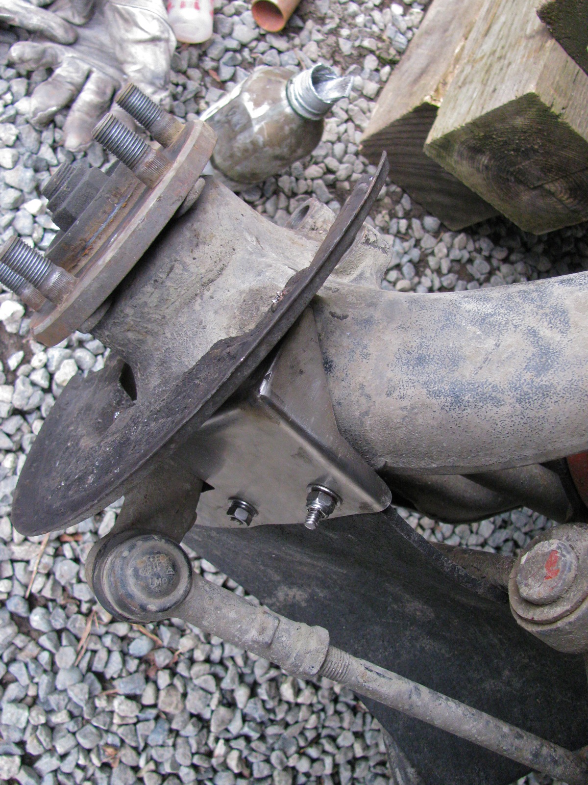
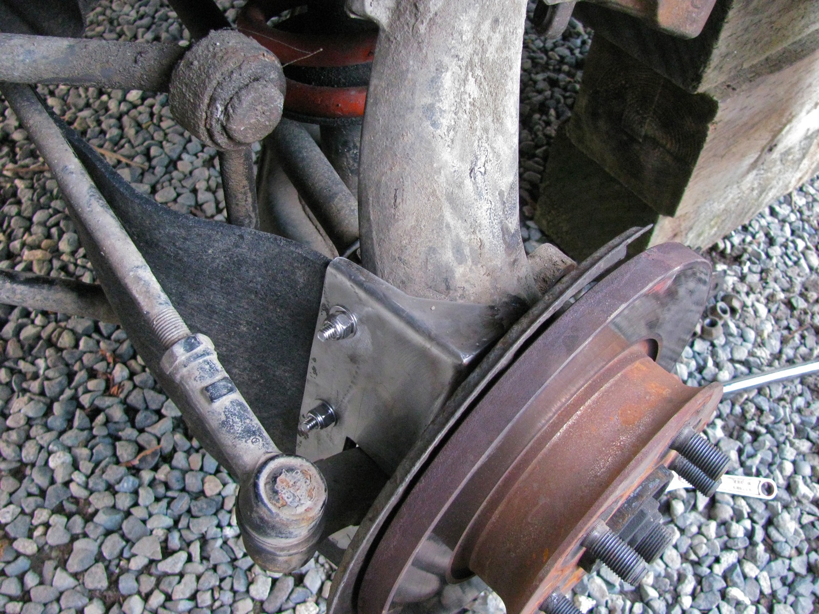
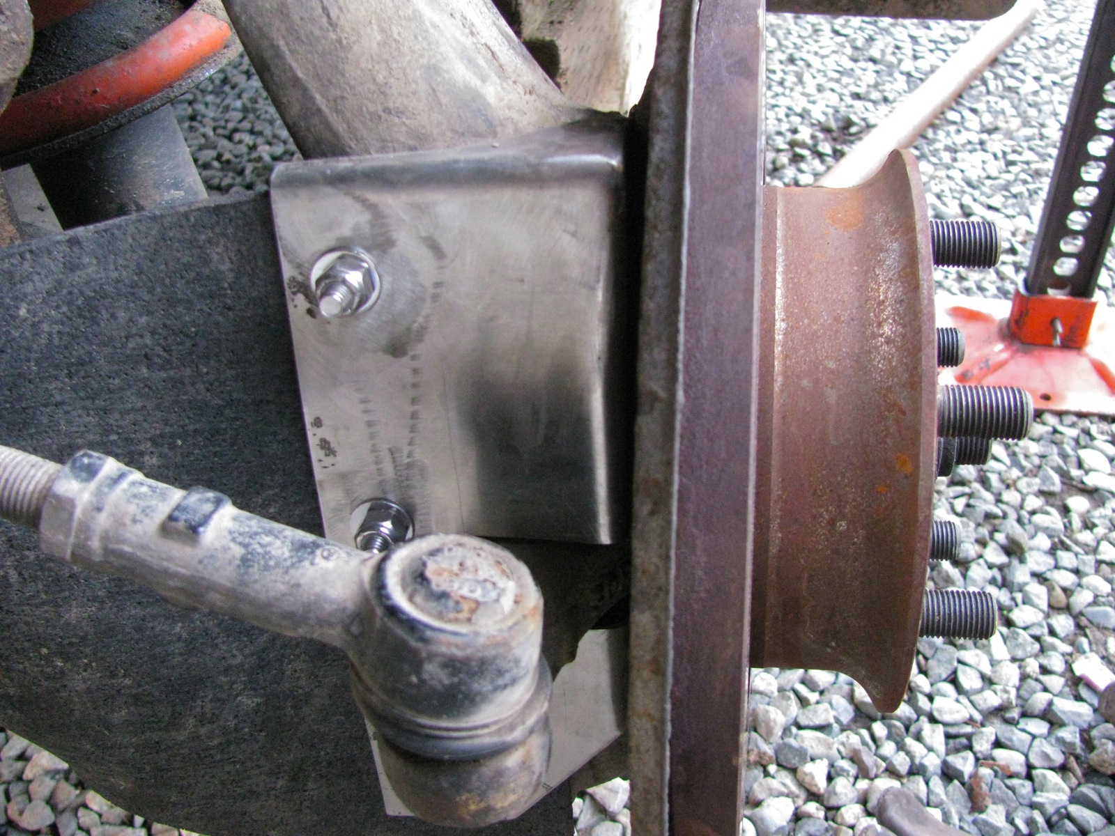
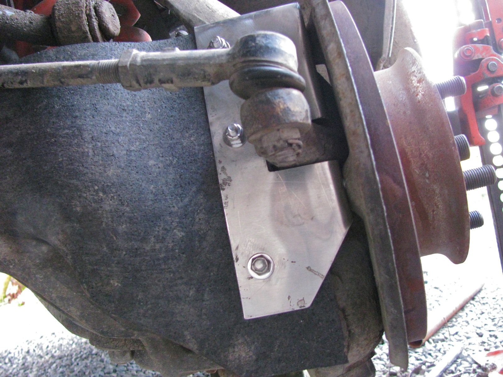
Once the splash plate is off the cv protector goes on and the splash plate reattached.
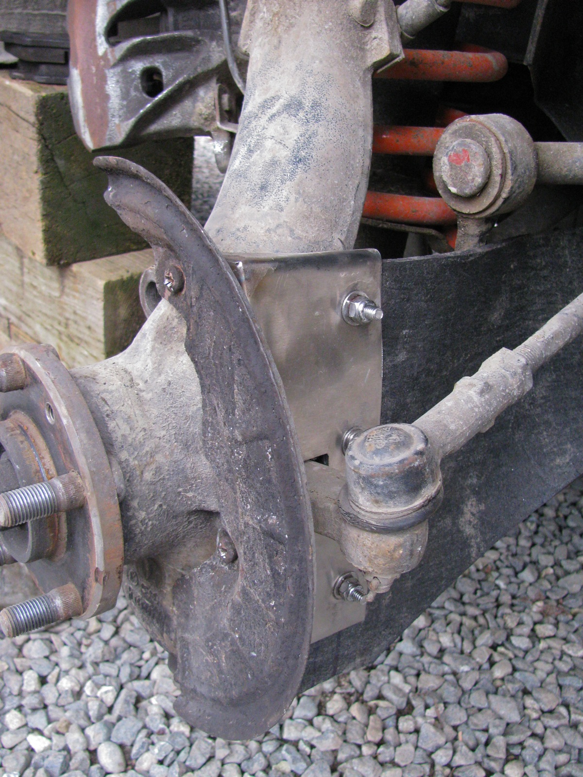
Another view.
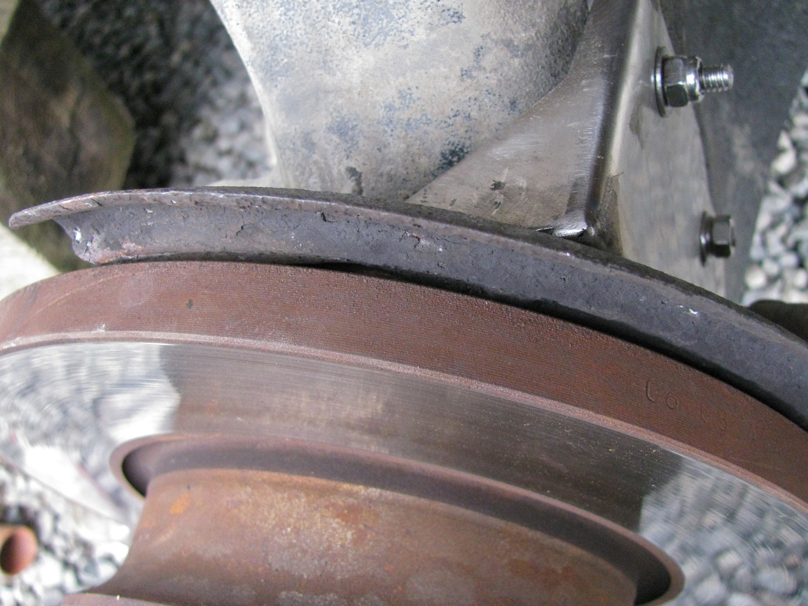
Brake rotor back on and the splash plate is now closer to the brake rotor by an amount equal to the thickness of the protection plate, but they do not touch.
The other side went a lot quicker.
And with the van down on the ground.


I got more satisfaction from this little mod than seems normal. I don’t know why this should be. Perhaps because I do worry about catching a branch up there when I’m on logging roads. Or maybe it is because the project went without any real screw ups.
Addendum/clarifications:
Vanagon – Spillbuster cup/glass holder
Posted by albell in vanagon, vanagon mods on February 10, 2013
Good friend Stephen gave me this for a Xmas present and I got around to installing it. Made in Germany of all places, I didn’t think the Germans encouraged drinking and driving.


I didn’t have the guts to try it with a liquid that would be a pain to clean up, so water it was, in a short trip around the farm.
Sheesh, spring already?
I know most of Canada does not follow the same schedule as we do here on southern Vancouver Island, but for goodness sake, this is too soon.

Vanagon – home made muffler installed
Posted by albell in syncro, vanagon, vanagon mods on February 4, 2013
Finally got the muffler installed. Some pics of components are in this post. Since then I made some rough mounting brackets, copy of the stock brackets, but made from aluminum (3/8″ plate) with some 1/2″ studs welded onto the sides (for T-bolt clamps). I didn’t take any pics of the brackets, perhaps I forgot on purpose as my TIG welds were overheated and sloppy (I’m learning, slowly).
Here are the brackets before final shaping, mounted to a spare engine mount.

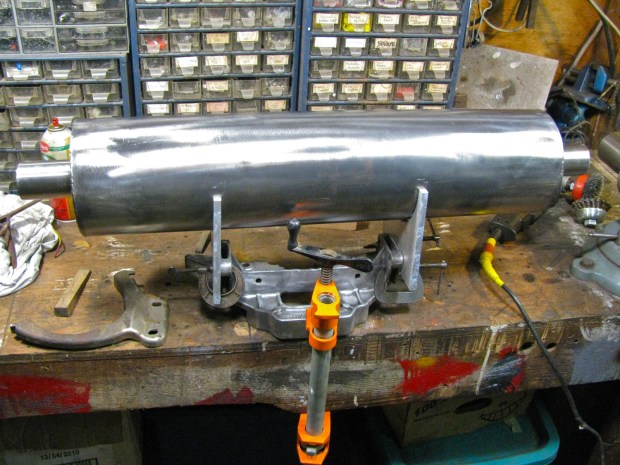
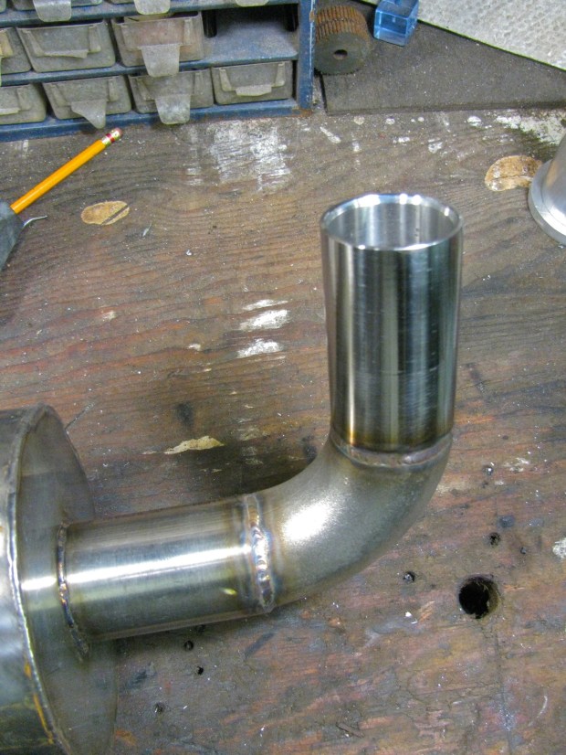
I copied the stock mounting brackets bolt holes and approximately the curves but adjusted to fit the 6″ diameter muffler. I also copied the relief curve on the bottom side of the brackets, allowance for the transverse connector exhaust pipe. A 90 degree SS elbow and a home made tail pipe was TIG welded on.
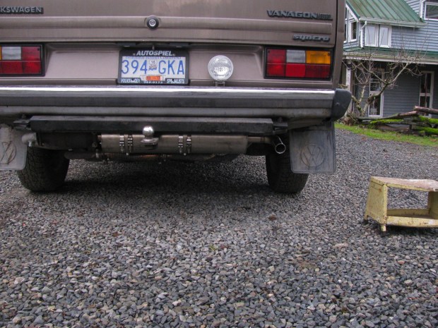
Install was pretty easy, brackets bolted right up to the engine carrier, ok, I admit, I didn’t get the muffler quite level. Once installed I realized I could have made thing a little differently to tuck the muffler up a bit higher. But all in all I’m pleased with how it hangs.

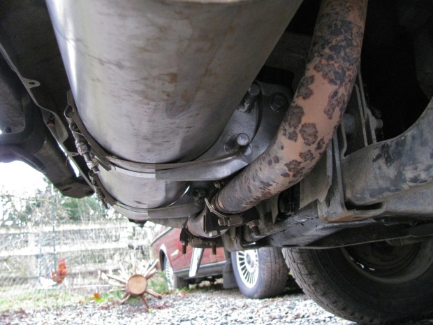
You can make out how the T-bolt clamps hang around the welded studs on the bracket. You might also make out the section of SS flex on the transverse exhaust pipe – a quick and dirty repair after cracking that pipe on a logging road trip.
And I made a little video to give you an idea of the sound. It is not as quiet as a stock muffler, but neither is it loud. Does have a throaty note.
I’ve always wanted (for some obscure reason) to make a muffler. And now I have, and by gum it worked. It’s the little things that get me through the day 🙂
