The story goes that VW introduced these protectors in 1990 for 14″ syncros with the rough road package, and on all 16″ syncros. Here is the English language bulletin.
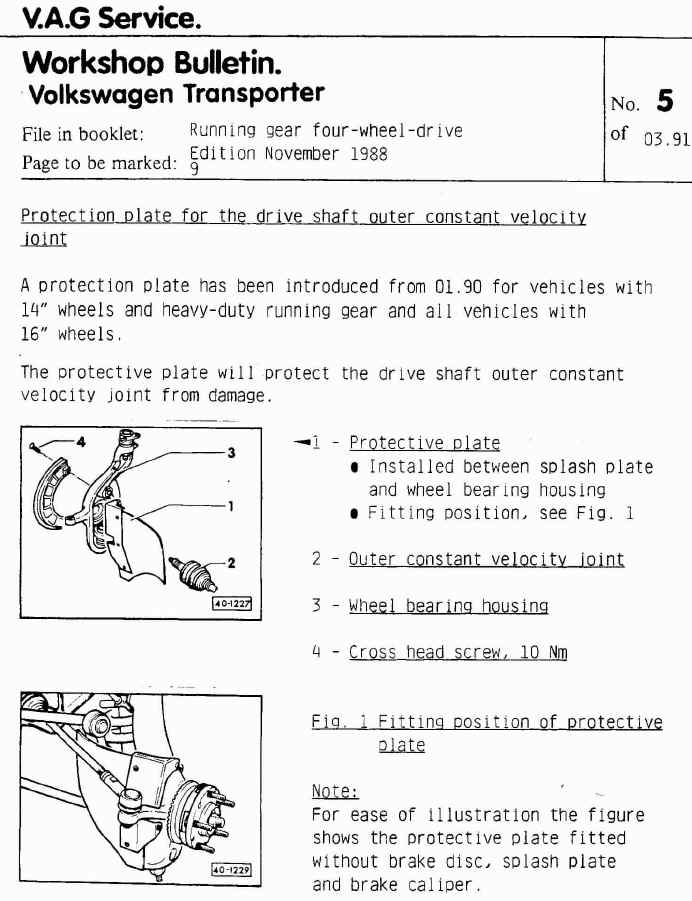
I wanted some. I worry about logging road debris catching on the front outer cv boot, and that boot is a pain to replace. You can buy them, one good source is Burley Motorsports, but seeing as there are plans for them on the internetubes I thought I’s have a go at making a set.
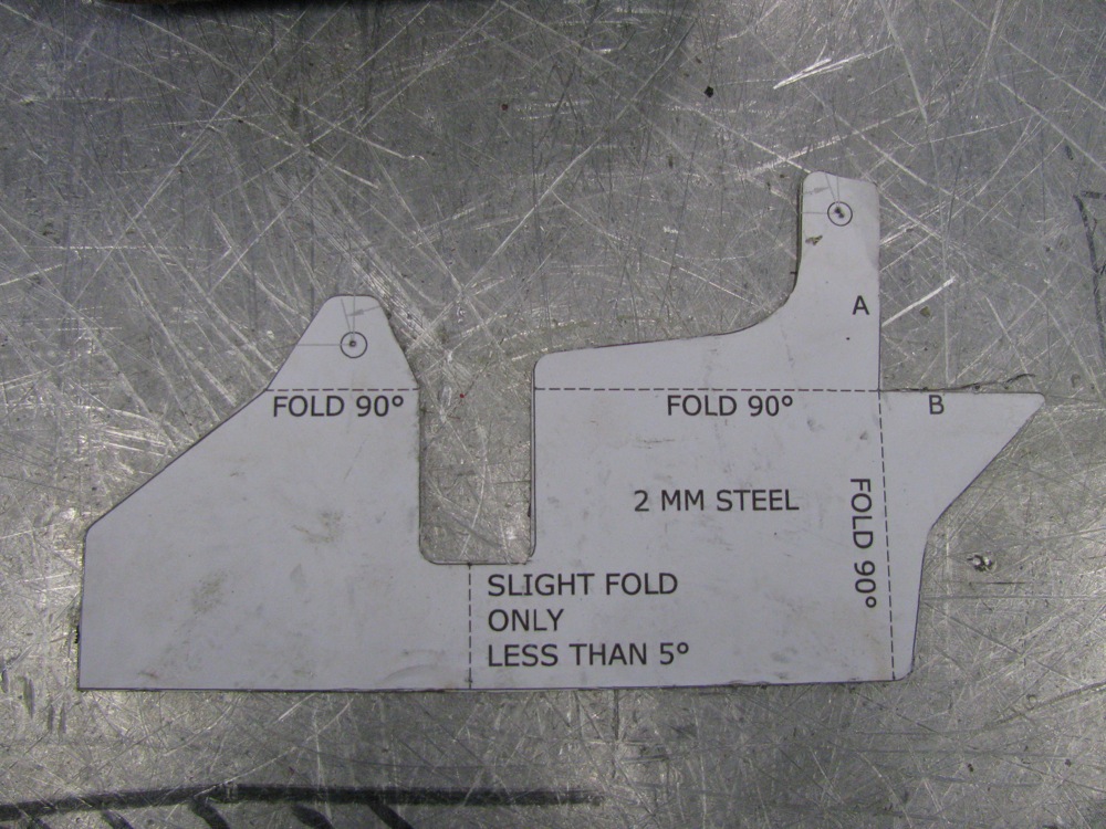
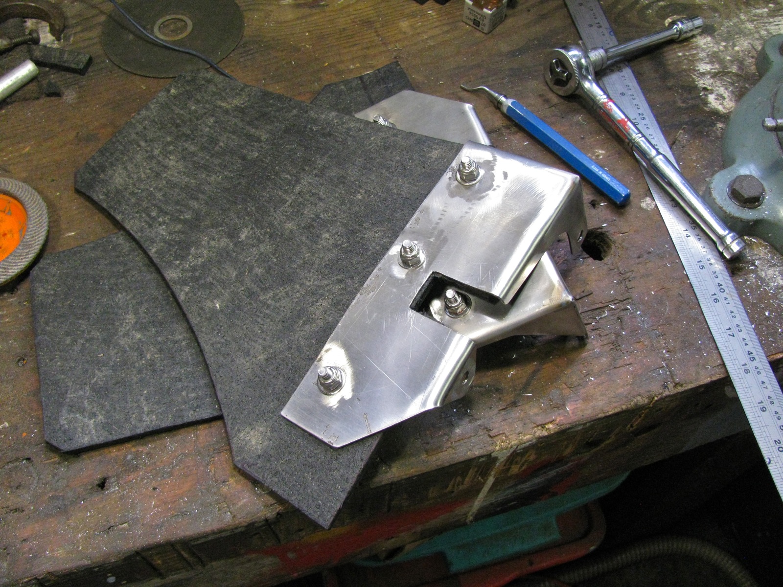
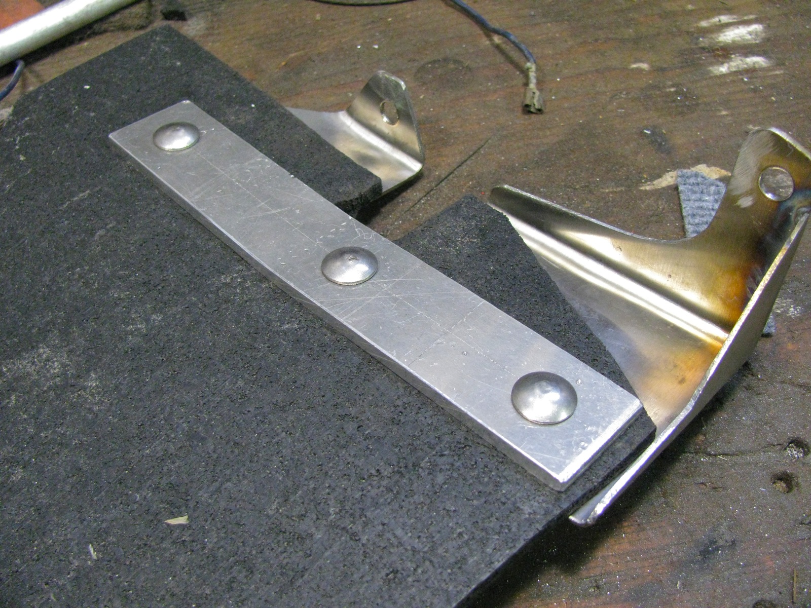
Here are the pdf’s of the plans I used: CV_protectors_bracket, CV_protectors_Rubber. I scrounged all of the material used, so my version differs slightly from the plans. First up are the metal parts. I had some scrap 14 gage stainless which is not quite as thick as speccified ( 1.6 mm vs 2.0 mm), and I glued a print-out of the plans to the metal and cut to shape.
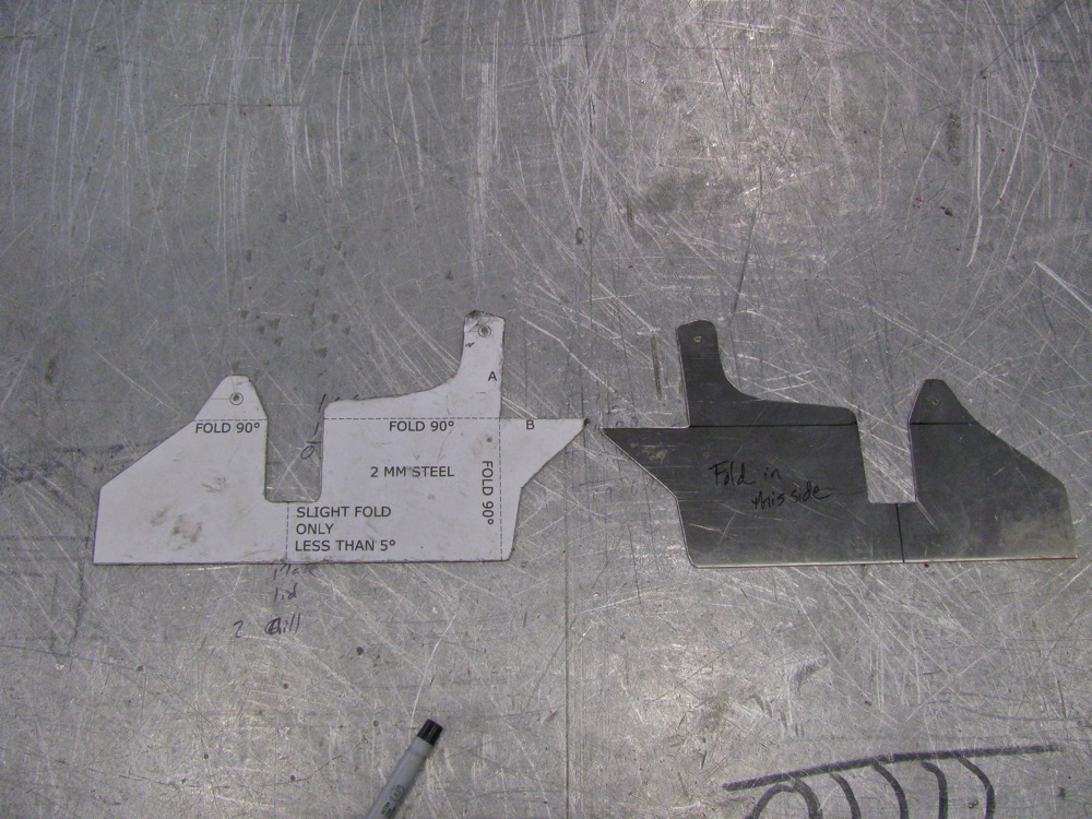
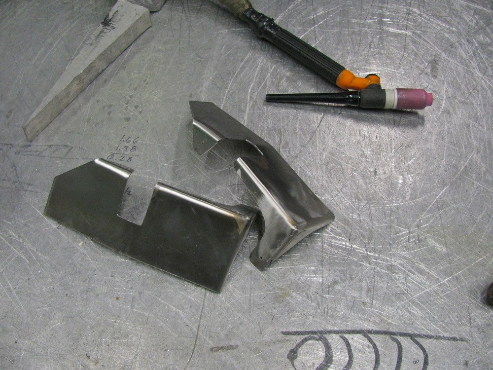
I bent the parts in a vise (that accounts for the less than crisp bends), then I made a hack-job of the tig welding. I need new glasses, well that is my current excuse for my poor welding.
Next was the hunt for rubber. You’d think it would be easy to find some 1/4″ thick, fabric reinforced conveyor belting, wouldn’t you? I spent an hour looking then I used some 1/4″ rubber sheeting that my neighbour had. It is not the best stuff, it is like thin horse stall matting. You know, crumbled tires pressed together. I can always replace the rubber when I find the belting. Ok, enough mumbling, I cut the rubber and I cut some 1/8″ 6061 aluminum for the backing strip. I used 1/4″ – 20 ss carriage bolts (the square part of the bolt shank will dig into a 5/16″ hole drilled in the backing plate) and nylock nuts to hold all the parts together. Well all but one, I ran out of nylocks and had to use a split washer and plain nut.
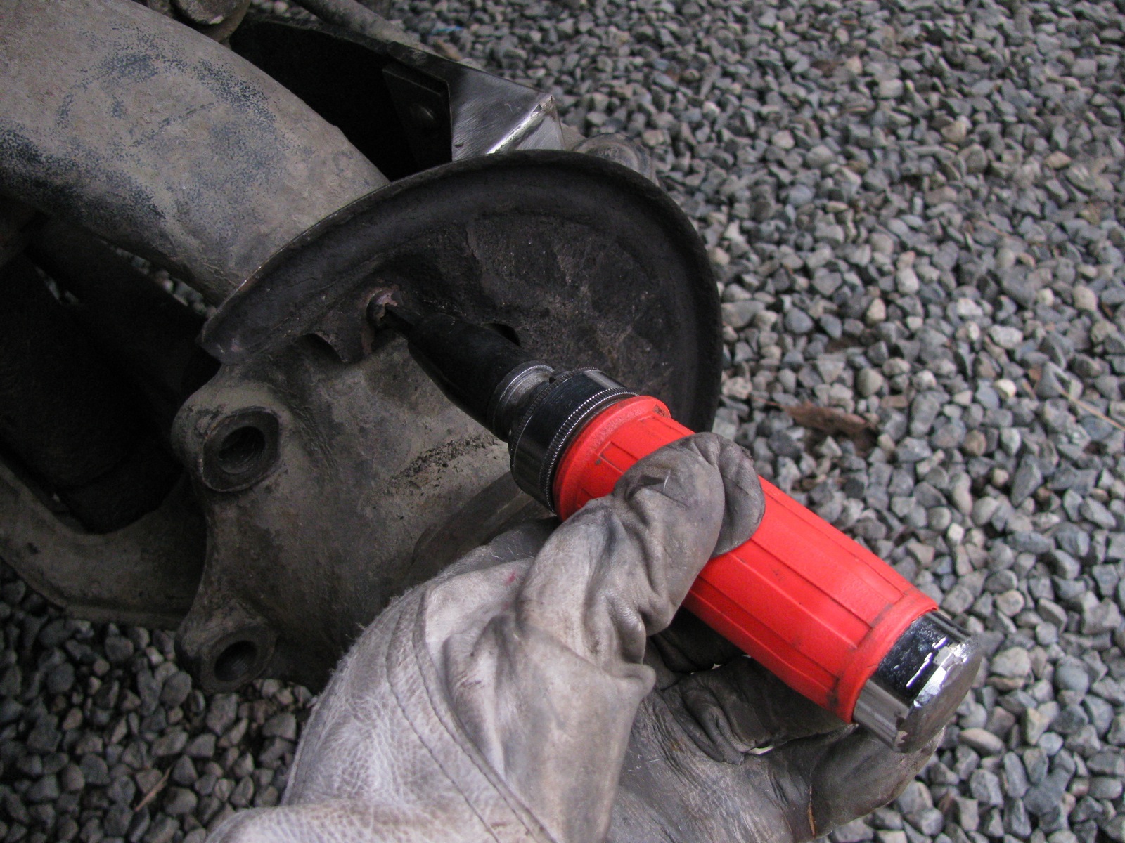
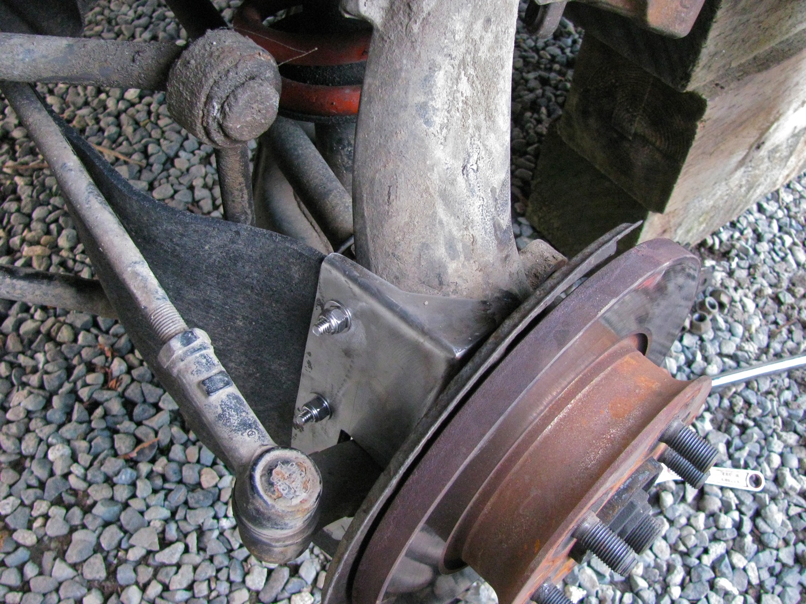
Okee-dokee, out to the van and installation. It is a bit of a pain, you have to remove the brake calipers and rotor to get to the backing plate. The same old but important safety warnings apply – van securely supported etc.
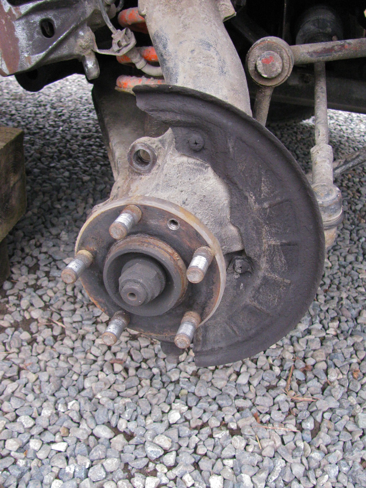
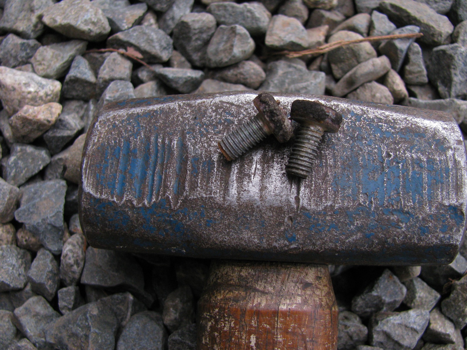
Two phillips headed screws holds the splash to the steering upright (or bearing housing, as VW calls it). They were fekkin tight, I doubt they had ever been removed. I had to use an impact driver, but even so I still managed to bugger up the screw heads a tad. I have said this before about my van, despite the ugly areas of body rust I have, all the fastenings (despite how tight they have been) are not rusted in.
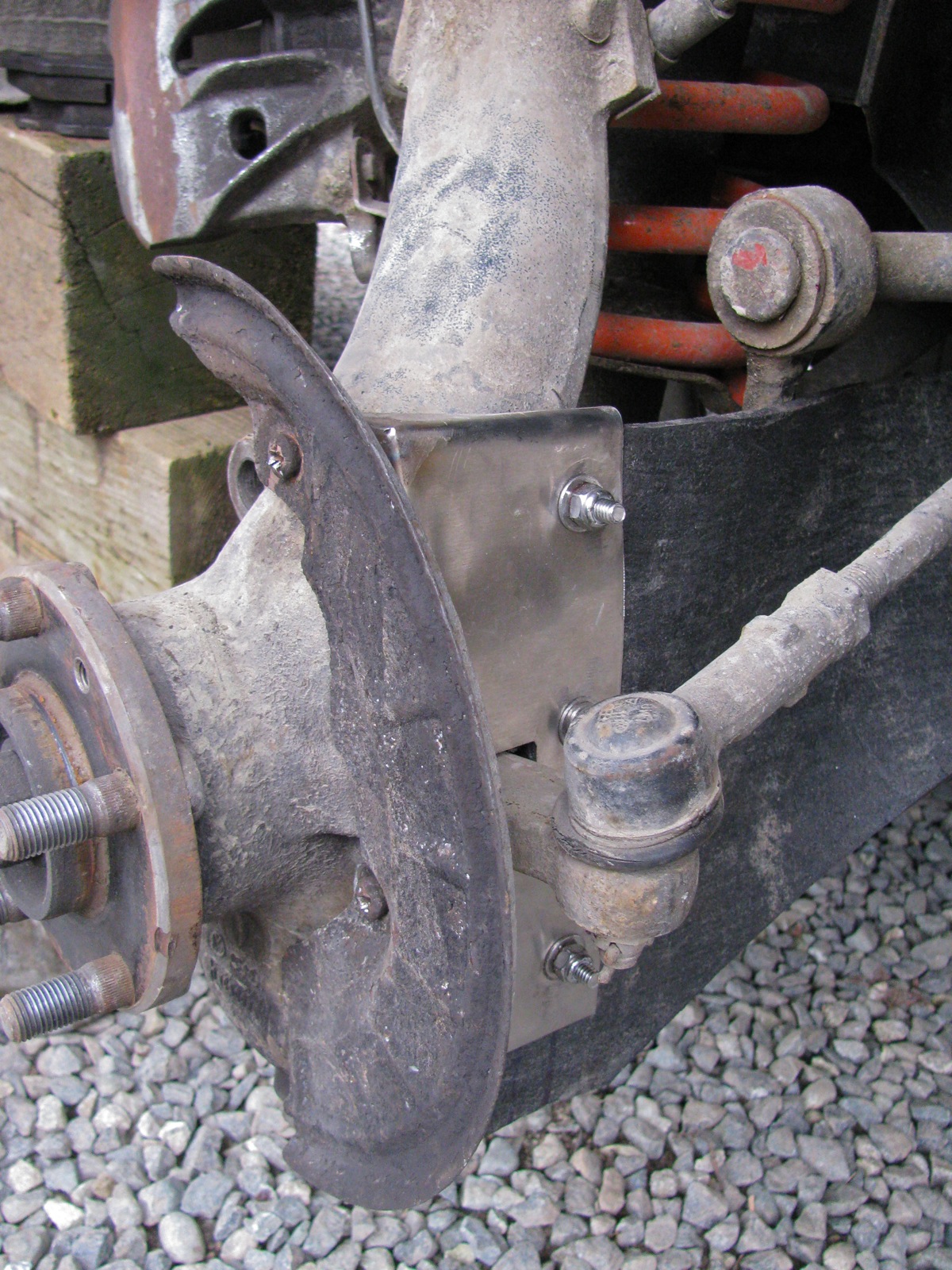
Once the splash plate is off the cv protector goes on and the splash plate reattached.
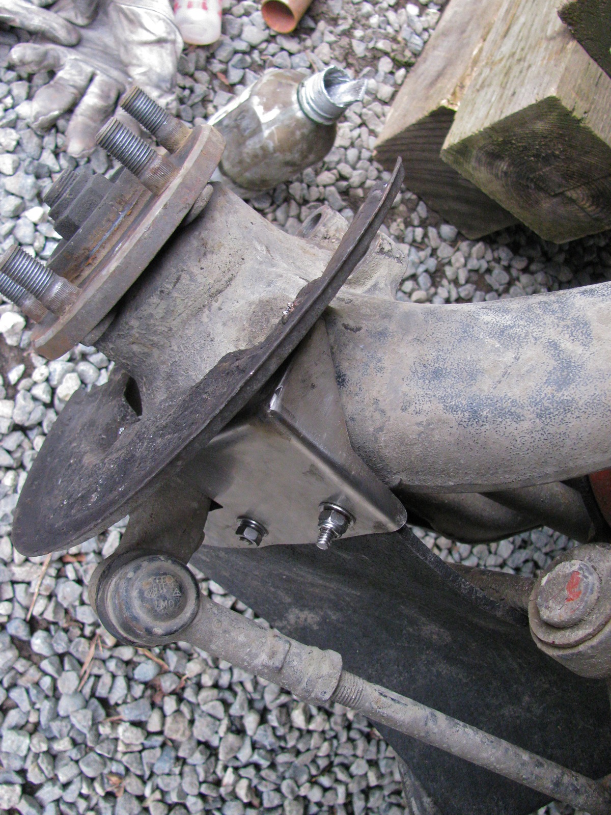
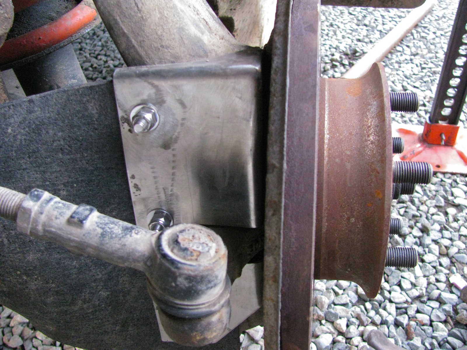
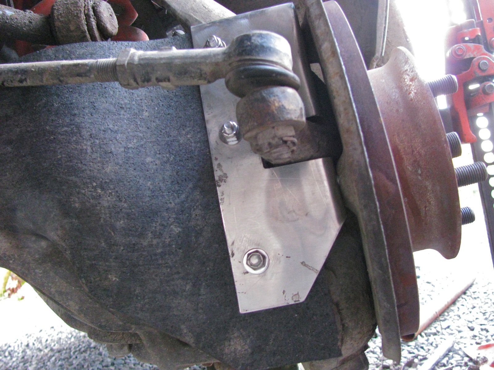
Another view.
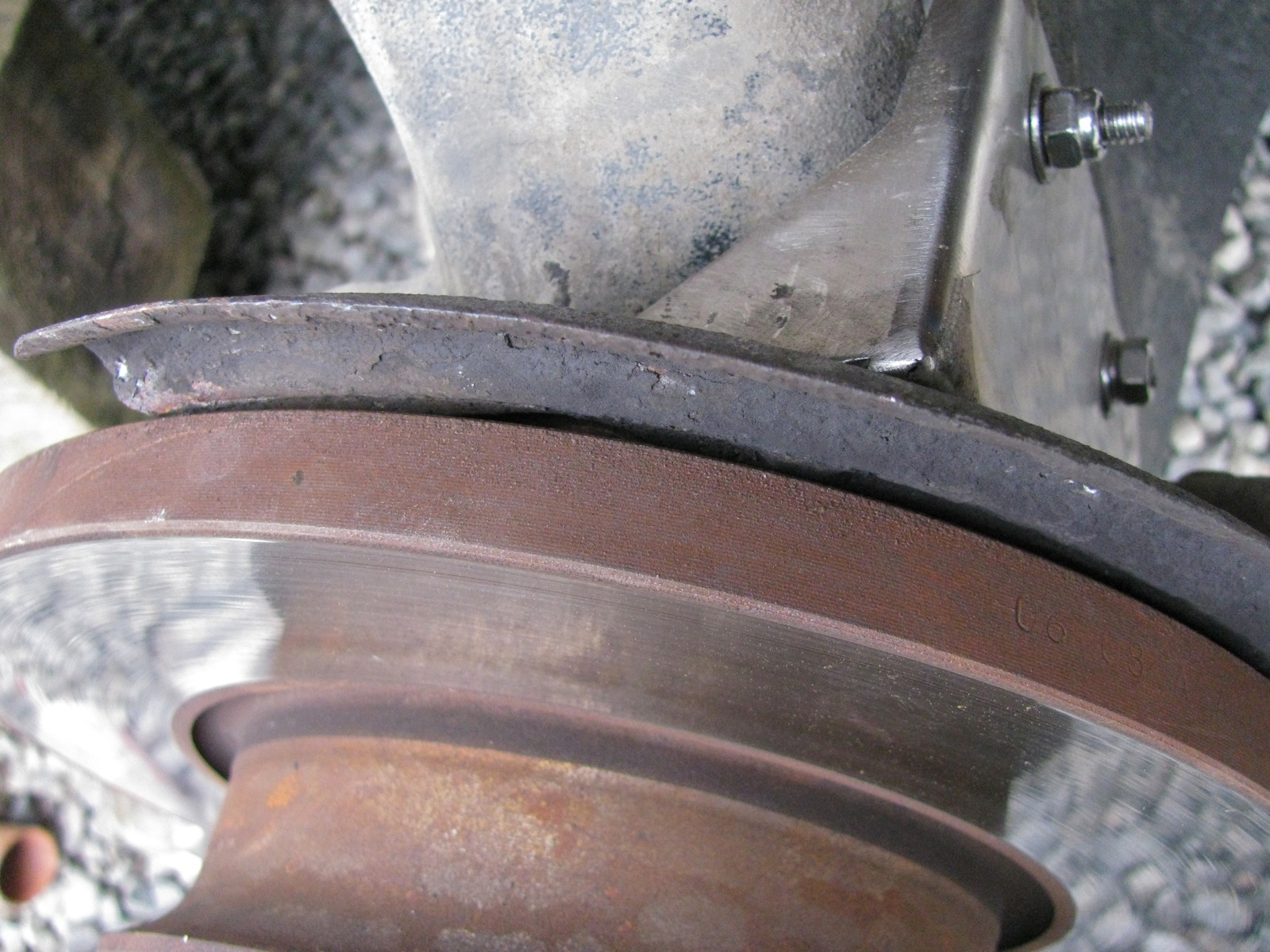
Brake rotor back on and the splash plate is now closer to the brake rotor by an amount equal to the thickness of the protection plate, but they do not touch.
The other side went a lot quicker.
And with the van down on the ground.


I got more satisfaction from this little mod than seems normal. I don’t know why this should be. Perhaps because I do worry about catching a branch up there when I’m on logging roads. Or maybe it is because the project went without any real screw ups.
Addendum/clarifications:

#1 by famillysyncro on February 17, 2013 - 5:38 am
Nice work as usual Alistair and a big thanks for the attention to details and the drawing.
Jerome
#2 by albell on February 17, 2013 - 8:16 am
Hi Jerome,
A couple of points on the protector (and I’ll add this to the post).
– the thickness of the stock used will move the brake splash plate out towards the rotor. So don’t go much thicker than 2 mm – I cut the material with a bandsaw and cleaned it up a little with file and deburring tool. Not pretty but it is not seen too well under there. – You see how I inserted the bolts from rear to front. It is not the cleanest looking way but I thought that it would be easier to remove the rubber and backing strip with protector installed. There is not much wiggle room behind the backing plate. As is I will probably cut down the exposed threads on the bolts to make it easier to push them (attached to backing plate) back and off. An alternative would be to make the backing plate out of stainless and weld the nuts on to it. – the stainless was bent in a vise. Makes for sloppy looking bends, but functional.
BTW, did I mention to you that I bought a couple of LED strips from Home Hardware? 2 X 2m warm white 60 SMD leds per strip. More expensive than online sources ($43 per strip, ouch) but the temptation was too great to resist. I have installed them (will send a pic) but waiting for dimmers ordered from SuperbrightLEDs. I like the quality of light they produce, and they sure do light up the van.
cheers
ab
#3 by famillysyncro on February 20, 2013 - 6:06 am
Oups I didn’t see that post….
Those strips seems to be more expensive but they give you a lot of nice light. It wasn’t easy to see o your picture, are they coming on roll or do you have an alu “profile” already?
It is hard to compare. I bought some a while ago from an electronic store ($20 for 50cms) and the quality was really good, really powerful.
Last one I bought are really cheap ($50 for 5m) but one need to be careful with the silicone on it that make them waterproof, it seems to be softer and it could be damaged. I noticed that when I was using pliers and rags to epoxy those magnets…
#4 by albell on February 20, 2013 - 9:29 am
Jerome,
yes, they are more expensive. BTW, I just got latest Lee Valley flyer/cat. They are now selling led strips! Have a look on the website – prices of strips (3 types of white, 3 types of rgb – all differ in led density) not that bad. Controllers are a bit large, but they have wireless ones.
My install – no metal strip or angle. I don’t find it glaring without angle shade on the strip mounted on underside of trough on sink side. Yes, the silicone is soft.
I just received my in line dimmers. They work well, dimming is in stages but suitable. The candle flicker setting is a bit bright, maybe I have not explored all the settings yet. The flashing and strobe settings wont be used much 🙂
cheers
ab
#5 by famillysyncro on February 20, 2013 - 10:00 am
I am not allowed to get the Lee Valley flyer, apparently, I spend to much lately… ;-(
We have a “touch” dimmer that will adjust the light step by step (didn’t use it for now) but I prefer those regular rotary potentiometer (drilling is needed) as long as you are room for them and not planning to move them.
Have fun with your new stuff.
Jerome
#6 by Peter Richardson on February 19, 2013 - 6:05 pm
Great job. Here is a link to a video showing the syncro front suspension at work. I agree with the thought that the rubber flap may end up being too large. http://www.youtube.com/watch?v=x5wY56iGrlY&feature=youtube_gdata_player
What about clamping a rubber flap from the tie rod and letting it hang down vertically in front of the joint instead?
Just a little armchair engineering on a blustery night…..
#7 by albell on February 19, 2013 - 8:25 pm
Peter,
thanks for the compliment. I like the vid of the front suspension in action. Good thing all of that is going on out of sight, otherwise I’d be distracted watching as I drive 🙂
I like the idea of hanging flap on tie rod, except I wonder if it would be enough to deflect branches etc ?
On this page is an animated gif of another flap in place. Note the different cut of the rubber.
http://www.furgovw.org/index.php?topic=166351.60
cheers
alistair
#8 by Martin Darlic on July 9, 2024 - 6:41 am
Hello, can you send me the dimensions of the project so I can do it at my house?
#9 by albell on July 10, 2024 - 11:25 pm
PDF dimensioned drawing linked in post.