Archive for May, 2013
Vanagon – Q and D head replacement – closing in
A few more odds and ends before the engine goes back into the van. In no particular order…
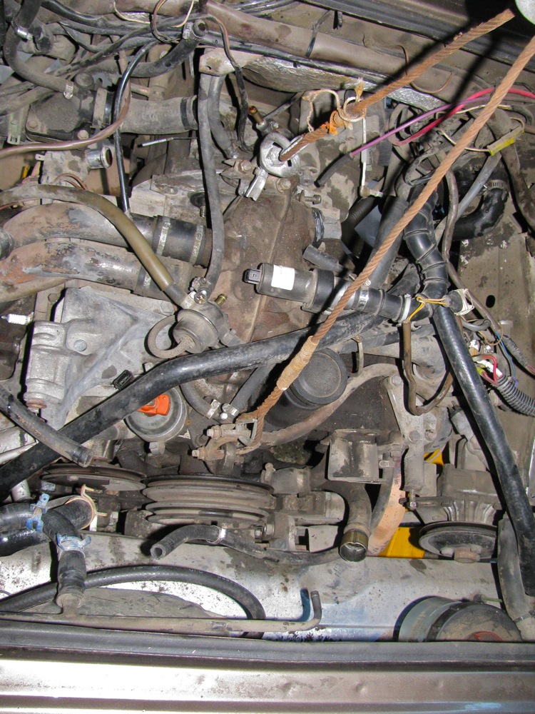
My diff lock light has not been coming on for a while now. I narrowed the cause down to either a broken wire, a faulty switch on transmission, or a bad connection at switch. I had planned on pulling the switch, but as I didn’t pull the tranny with the engine, and as is (ie the vacuum actuator still attached to tranny) I could not get a wrench or a socket on the switch to remove it. See how tight (ie little clearance) it is?
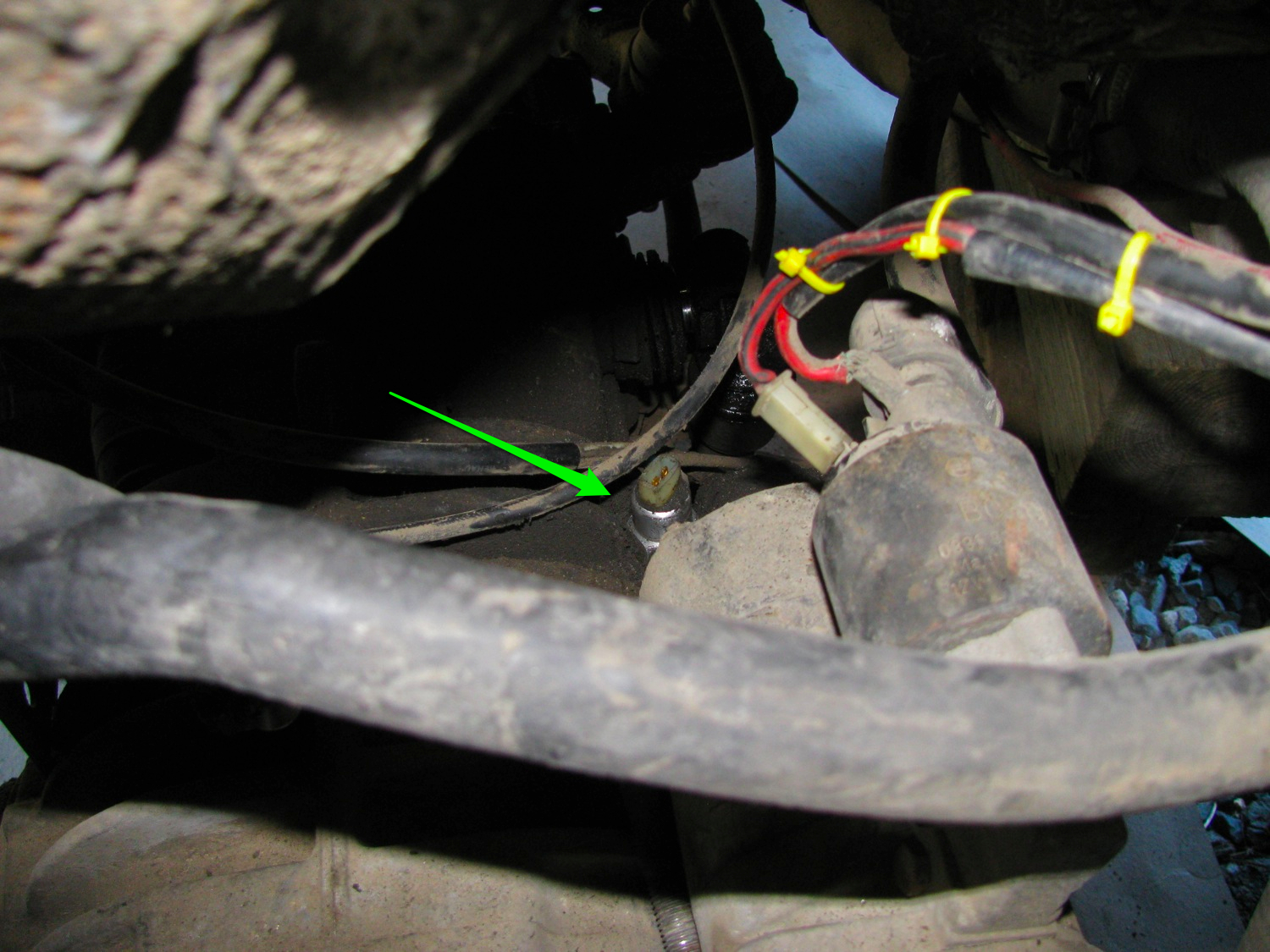
So as I stand there, kicking myself for not pulling tranny, I decide to cut open the bundled wire sheath to see if there is a broken wire where they make some tight bends. No luck, all is good, so I pull back the rubber boot on the connector and one wire comes with it. Did I just pull it off or was it broken already? Of course I am pumping for the latter. I fixed the connection and put it all back in place. Fingers crossed.
I forgot to mention before this that I found a bent pushrod when I took the heads off. If I remember correctly, it was on the side with the (leaking) spring loaded pushrod tubes. How does a bent pushrod affect the engine if the valve adjustment is done correctly?

I’m re-using the clutch drive disk and pressure plate and I measured things to check if that was a good idea. There is still some good life in the disk and the pressure plate has all its finger and is flat. The flywheel is ok too, I de-glazed with fine emery and I replaced the O-ring. The old one was quite stiff.
I did some head scratching when it came to the support bracket on the rear exhaust manifold. Seems that the syncro muffler carrier has extra holes in it to attach the bracket. As I have home made aluminum muffler carriers I had to drill some new holes. Pretty tight, not much wrench clearance. I’ll curse myself if and when I have to get the bracket or carriers off.

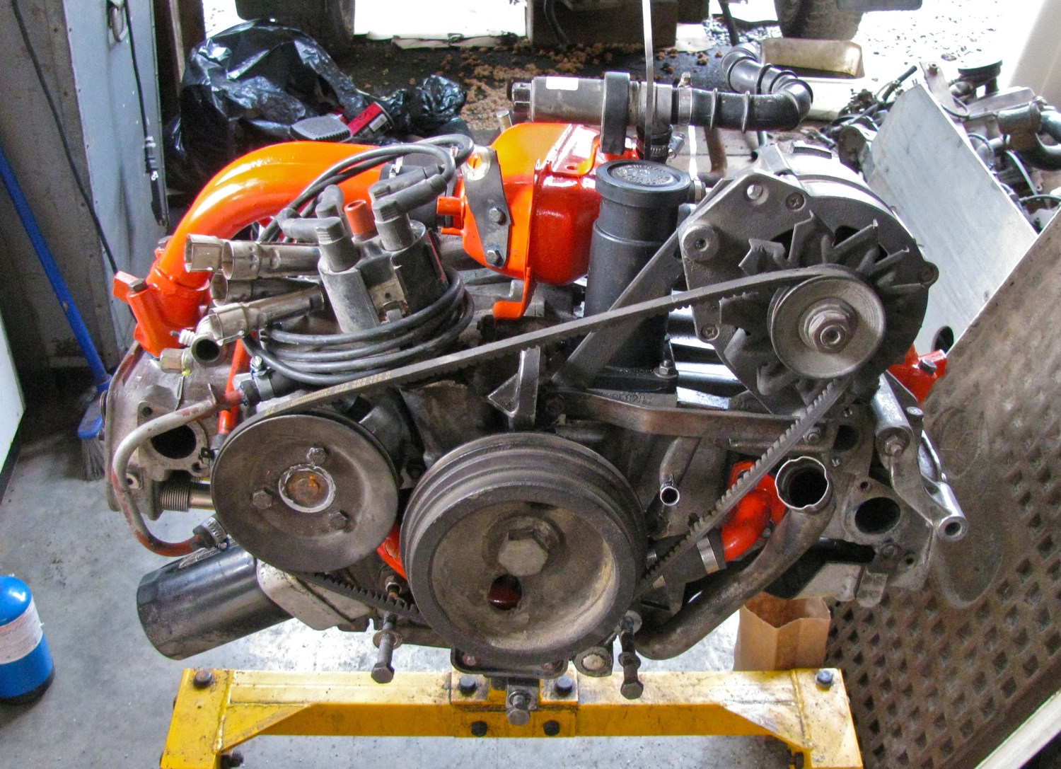
Boy am I happy to see the engine finally in this state.

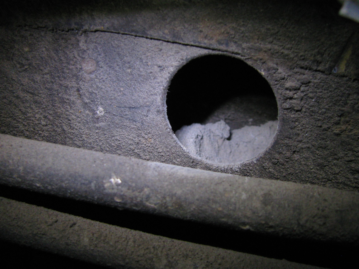
Oh, and when I was in the engine bay I looked into the holes in the frame members on either side of the bay. The frame members that further back house the bumper mounts. A lot of dirt in there.
Next job is to move the engine from the stand to the hoist so that I can get the flywheel and clutch back on.
Vanagon – Q and D head replacement – A little update
Life, god bless it, intruded on the project a bit. So really not much progress to report, but what I have I give to you. (sheesh!)
Way back when, I played around with an oil pressure switch relocation set up. I blogged about it here. I saw no reason not to whack it onto this engine. Some notes about the install:
– threaded hole between the pushrod tubes, where one of the 2 oil press. senders originally fitted, is M10X1.0 thread. I used a brass adapter, male M10X1.0 taper thread by female 1/8″ NPT. Note that I have got a male taper thread going into a female straight thread. I was assured that this will seal up fine.
– Then from the female 1/8″ NPT we go to 1/8″ soft copper pipe via a compression fitting. A better way would to be to go to brake line rather than copper, more vibration resistant.
– copper line sheathed in fuel line
– stainless steel cable tie securing line to pushrod tube. Not really needed, the line is pretty solid in it’s run (the covering stiffens things up a bit). I worry about the tubing vibrating and putting stress on the compression fittings, but as it is, the tubing is routed pretty nicely, tight and secure.

– the line runs up tight to engine case and out to the top surface between case and thermostat housing.
– I had to use a 45 degree 1/8″ NPT female to male to make the turn. A 90 degree fitting was too tight. Then we have another female 1/8 NPT to male M10X10 adapter which goes into the manifold.
-due to that little pipe that goes from water pump to Tstat, I had to make a little spacer to raise the manifold about 2 cm.
– that side pushrod tube protection plate had to be reworked a little. I’ll get a pic of that sometime.

At the rear of the engine, just to the right of the water pump, the now vacant M10X1.0 hole (which is actually a reduction bushing) can have a temp sender probe fitted. I had this nice VDO sender (used it for years on my I4 engine in my ’82 westy) and popped it in there. Later I broke the bugger when I Was going round checking that “I had tightened things up”. Bloody hell. Local autopart stores could not get me a new VDO sender anytime soon, so I took a chance went for this sender (MKII/MKIII Golf). I don’t care that it is shorter and not reaching as deep as the other one. Well I do care but will it *really* make that much difference? Pic showing senders and reduction bushing.


Installed in engine. Signal wire running up then back over top of engine and I’ll bundle that up with the oil pressure sender wires.


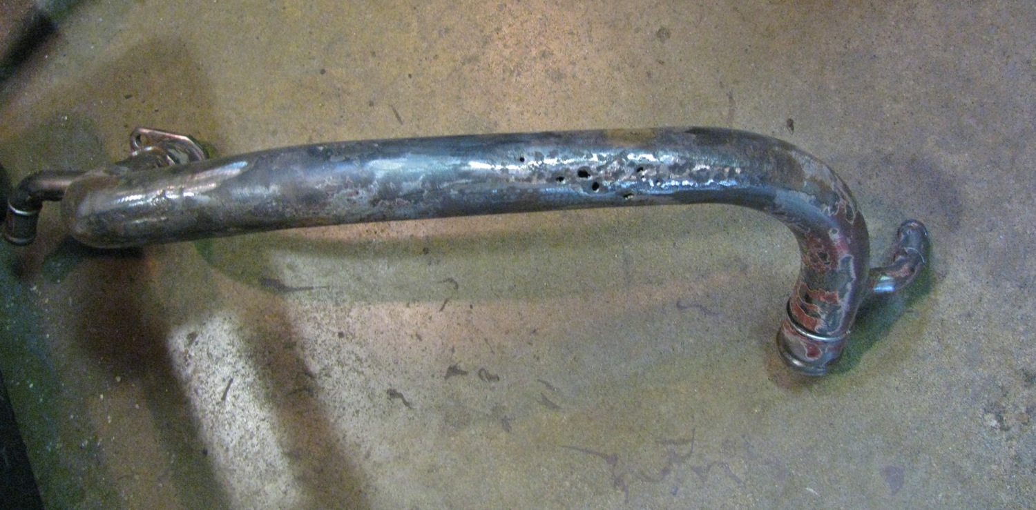
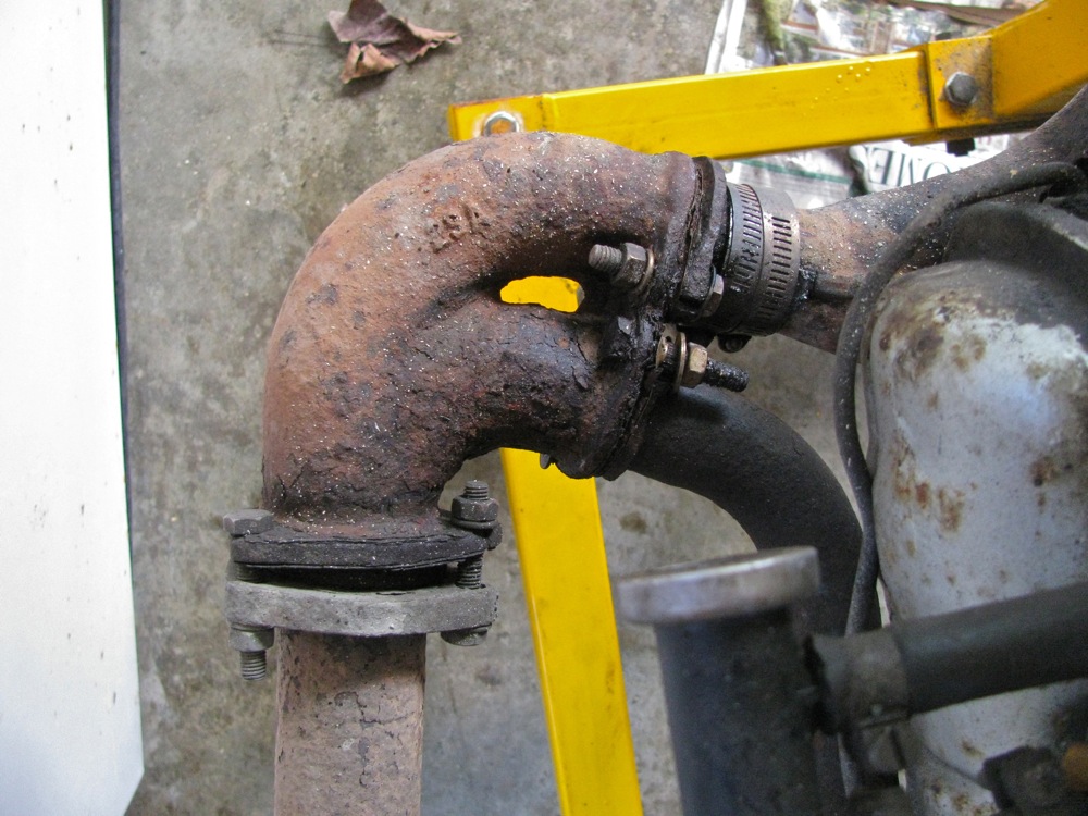
Remember my rotted coolant pipe? Well I found another. less rotted one and decided to patch that one up. It had one hole in the main pipe and another one in one of the side pipes. I brazed the holes closed and then slopped on more braze to fill in some minor pitting. That pipe, especially just at the bend where it comes up to connect to the Tstat housing is very exposed to the elements and heat from the exhaust pipe. The combo of heat and weather causes the paint to be eroded and the pipe to corrode. I had the idea to weld on some tabs to allow a little shield to be installed, but I had blobbed on the braze before I remembered and the TIG welder was being used on some serious stainless welding so I left the tabs off. I might try and clamp on a shield. Not the best way, the clamps might be a locus for corrosion starting. I painted the repaired pipe with POR 15, and then with some orange engine paint.
I encourage those of you with old 2.1 WBX engines to check this pipe. Poke at it with a screwdriver or an awl. Make sure it is not on the edge of failure.

I have to say that this project has been much more work than I thought it would be. I not regretting doing it, my god the rotted coolant pipe alone has made it worthwhile. But I have been distracted and unable to concentrate during the job and that is annoying me.
More to come, this job will end 🙂
Vanagon – Q and D head replacement – surprise
Catching up on my progress. I spent yesterday (Sunday) adding the bits and bobs that go on the motor. Intake runners and plenum, coolant lines, oil cooler, PS bracket, alternator bracket, dipstick, etc. A bit of a disappointment when I fitted up the spare rear manifold and found that the end did not line up with the end of the new front manifold. Not even close. I thought that the rear manifold was the same for all 2.1 engines (apart from, perhaps, the small support clamp and bracket) but this one was nowhere near close to working. The angle at the end of the pipe where it meets up to pair with the front manifold was all wrong. I bought a new one today and it works, but needs some slight adjustment.
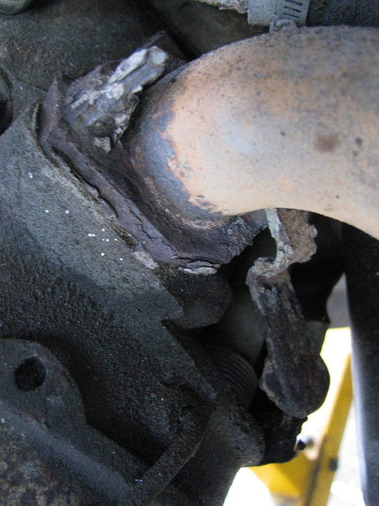
But the real surprise yesterday was the coolant pipe that runs from the water pump forward along the left hand side of the engine to connect with the thermostat. I had forgotten all about it when painting other bits and yesterday, when I was going at it with the angle grinder powered wire brush I uncovered this.
Wow eh? I think the paint was all that was protecting me from a massive coolant leak. Talk about lucky. This one discovery almost makes this entire ordeal worthwhile. I’ll talk about what I did about this in a later post. One more pic, before I put the rear manifold on.
A personal issue has complicated things, but I hope to get this thing done in the next few days.
Vanagon – Q and D head replacement – am I winning?
It has been a bit of a chore.
I can’t recall if it was last Friday when I updated last, here goes with a catch up of what I did on Saturday. I think it was Saturday, my weekends and evenings are so filled with gallery openings, theatre premiers, cocktail parties, and the occasional orgy that I often lose track of time.
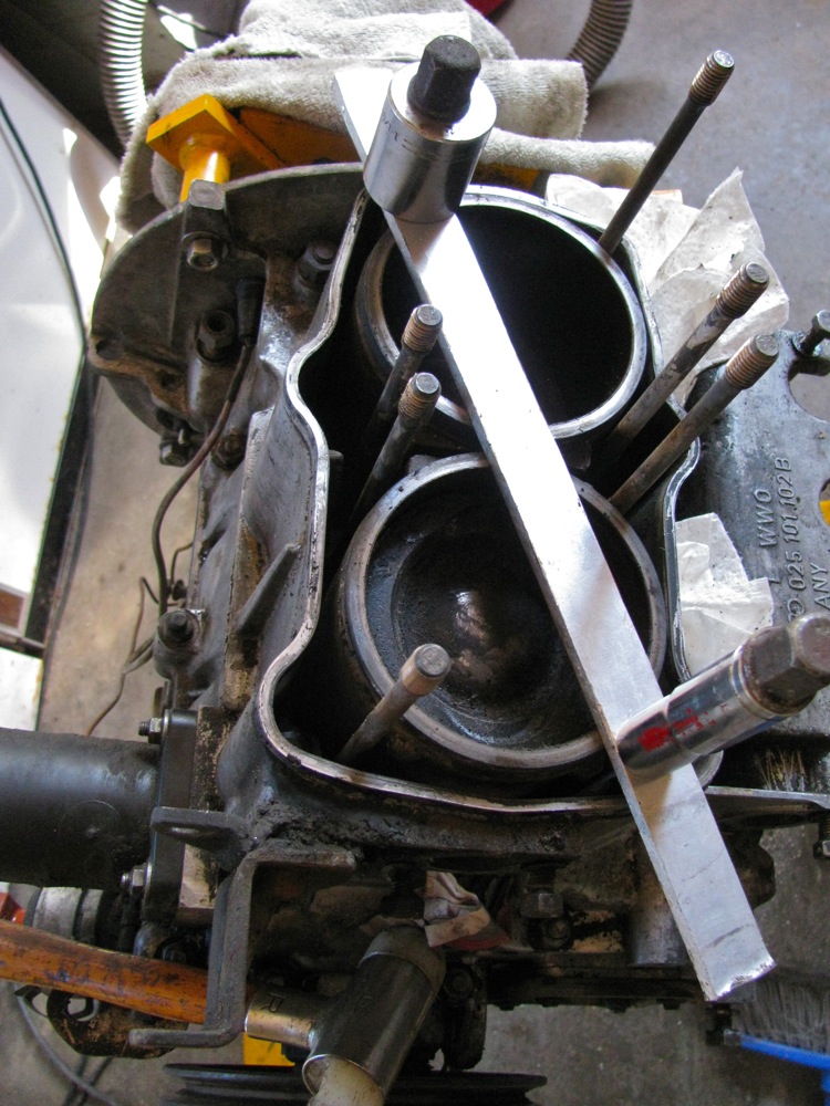
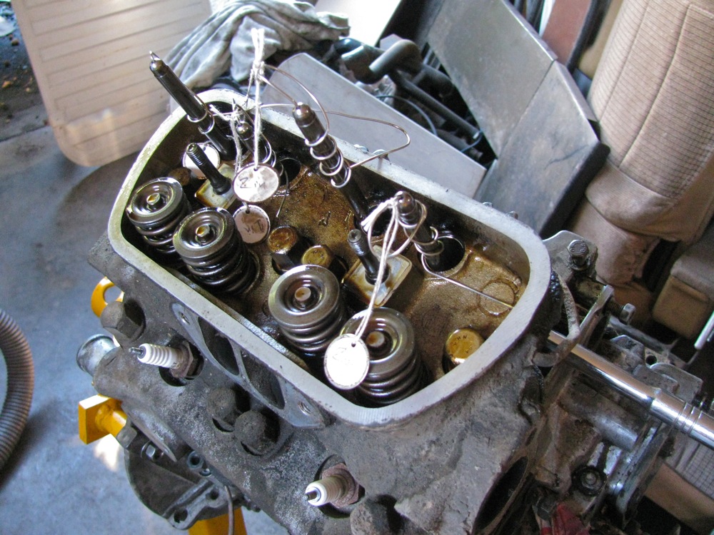
First off, a pic of how I keep the cylinders in place whilst rotating the engine on the stand.
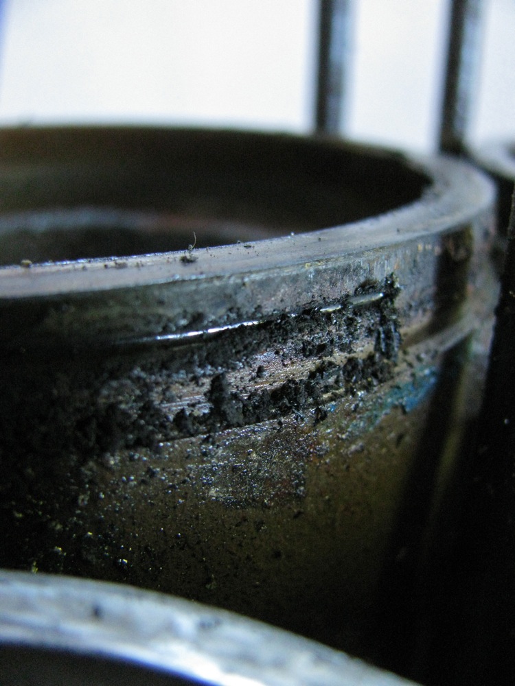
Removing the head from cyls 3 and 4 was difficult. The heads were stuck fast. Lots of tapping with brass drift got #3 loosened, but #4 was a real bugger. I finally got smart and ground the end of my pry bar so it had a sharp edge to catch on the tabs on the cylinder top, final pry and it was free.

Oh that thin green O-ring at the top of the cylinders, not doing much now eh?

Digging it out (dental pick).
I was getting on fine with the clean up, then disaster struck. I inadvertently, or stupidly (take your pick), pulled #4 cylinder up too far and the bottom (oil) ring came out from the cylinder. “Oh darn it” I said.
Over the next few hours, during which I had no inclination to take any pictures, I pulled the cylinder right off, removed the wrist pin on #4 and took piston out, decided (rashly) to pull #3 cyl too but left that piston on con rod. With them on the bench it was easy to really clean the cylinders. And I was able to clean up #4 piston.
Ok, back to assembling rather than taking more things apart. I used a regular sized ring compressor to get #4 piston and cylinder together. Oh and I cleaned and polished #4 wrist pin, even so it was still a tight fit.
I cut down another of my ring compressors so that the compressing band was about 5 mm wider than the distance from top to bottom piston rings. This particular spring compressor could be taken apart. The head bolts and water jacket restricts access to #3 piston even with #4 piston and cylinder removed, bit the compressor worked like a champ and I got the cylinder over the piston first try.
But… when I was removing ring compressor a part of it fell into the open spigot of #4. “Oh gosh darn it”. The piece was aluminum and my Al magnet was at work. Rotating the engine didn’t work. I finally pulled #3 cylinder again and the lost part was tucked under the piston skirt.
Ok, again, cylinder back on, compressor removed very carefully, then the assembled (on bench) #4 piston and cyl brought over to do the gynecological insertion of wrist pin through water pump and into (flopping around) con rod. VW has a special tool to hole the cond rod in place, but I did it by getting the engine rotated on stand “just right” so con rod hung in position.
Phew!
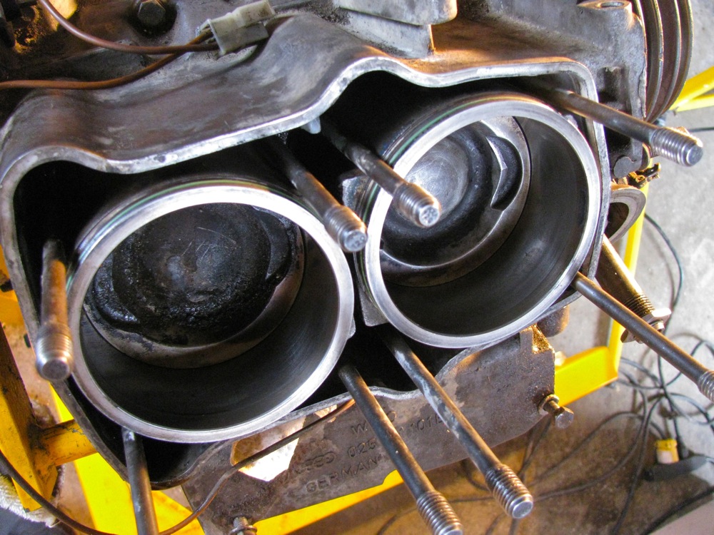
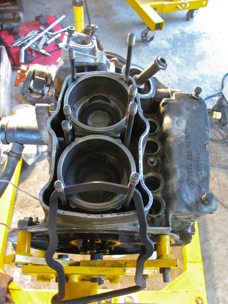
Pic taken just before all that.

And after things back together. Also replaced black O-rings at bottom of both cylinders.
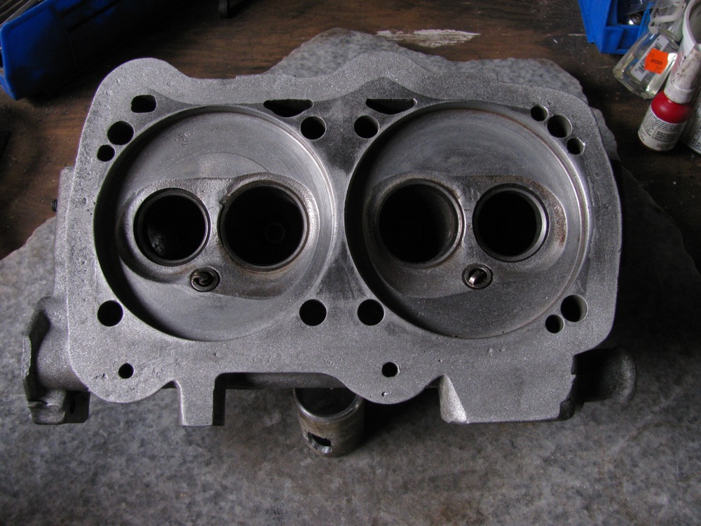
Back on the heads, using a spare cylinder I “lapped” where the cylinder meets the head.

Fine carborundum powder, oil, and twisting the cylinder back and forth. Then I cleaned up the heads, blasted with compressed air, re-installed valves (gave them a little lap love too), then degreased the surface where the rubber gasket seals.

Then on to the oil pump. What stalled me here was trying to remove all of the old paper gasket. The paper was really stuck on and one did not want to scratch up the mating surface. The endplay on the pump measure out to 0.002″ (wear limit is 0.004″) so I decided to use the new thin gasket during re-assembly. Some say to use just some sealant if endplay is close to wear limit. I lapped the pump cover to remove the pump score marks, don’t know how useful that is.
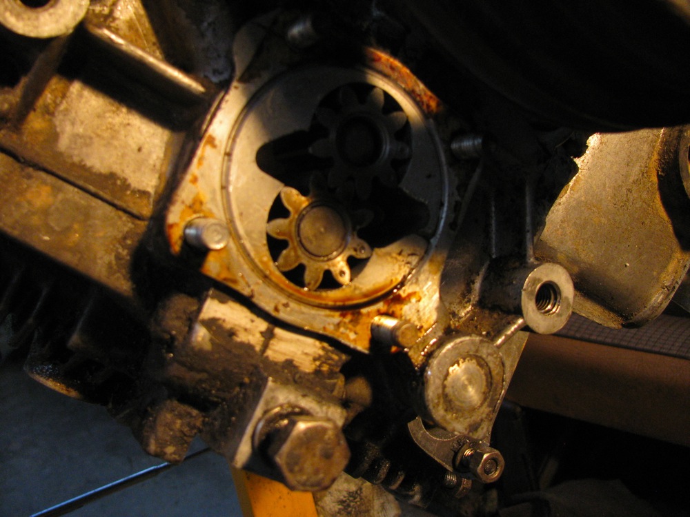
And now the rubber gasket. I used the Reinzosil sealant that came in the gasket rather than “The Right Stuff” (and I do have a tube of that). Why? Well why not? All accounts are that it is good stuff, improved from the original. A thin bead applied to the grooved side of seal and the seal placed on the water jacket. Then a thin bead down the centre of the mating surface.

Then the head….
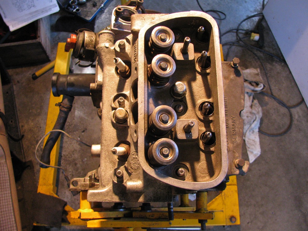
Cleaned up pushrod tubes, checked them for length so they would have good “push” when compressed, put on new seals. Clean and dry holes in case and head.
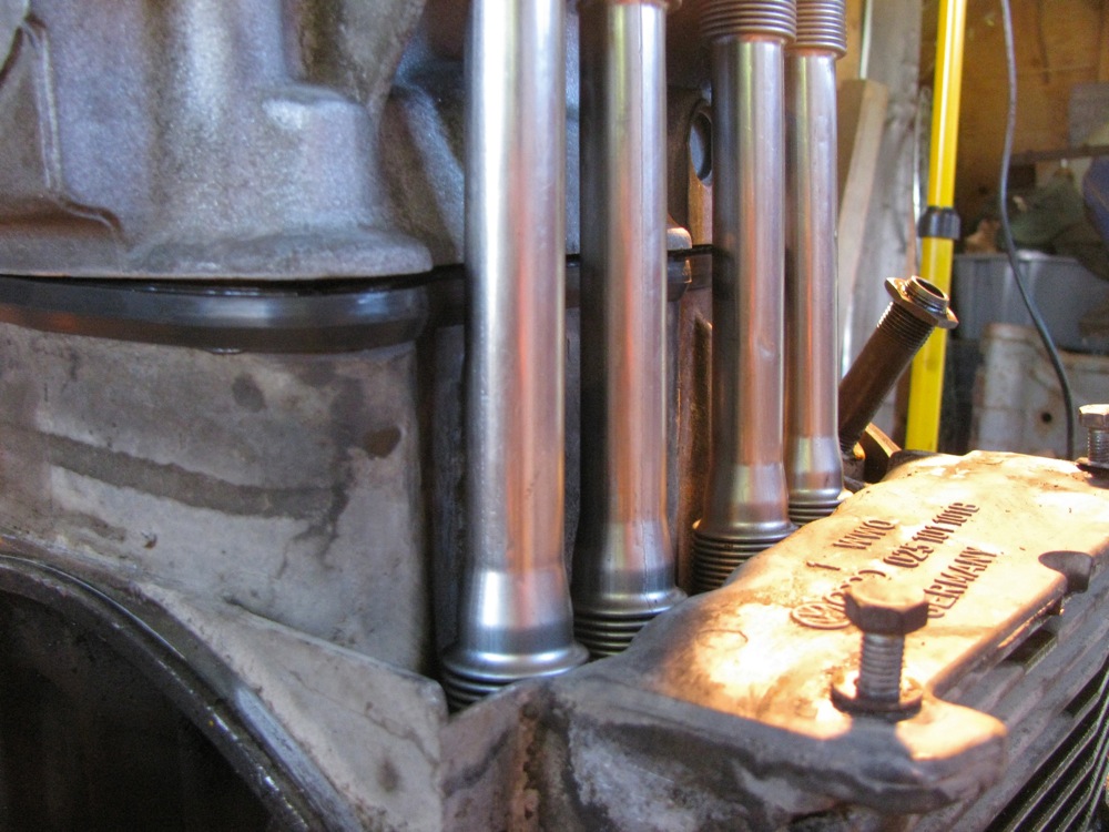
I used cap nuts on 2 centre bolts to pull the head down (compressing pushrod tubes) enough to get the rest of the cap nuts on. Yellow sealant applied to the head rather than the base of the nuts. It all went rather easily. Torqued the head down in 3 stages – 10, 25, and finally 40 ft/lbs.
I numbered the cap nuts in torquing down sequence. I was nervous, numbering the caps calmed me down 🙂

And I got the other head on with no drama. I had to check the fit of my new exhaust manifold (Dansk) and it fit up to the heads as if it was made for the job.

Then I started putting things back on. A cleaned up, inside and out, breather tower with new O-ring, new waterpump, and one newly painted coolant pipe.

Enough for this post, I’ll try and catch up on my progress in next post.
Vanagon – Q and D head replacement – progress
I got somewhere today but realised that there is much more dirty than quick in this chore. I transferred the engine from hoist to stand then set about taking off all the ancillaries.

This pic shows the backside of my muffle mounts. Also shows my stainless steel flex hose repair to exhaust pipe (I whacked it badly on a logging road over a year ago).
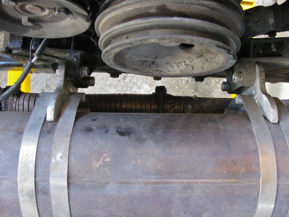
More exhaust shame. I’ve re-kludged the end connection of that pipe many times over the years. Oh frabjous day when the new pipe goes in.
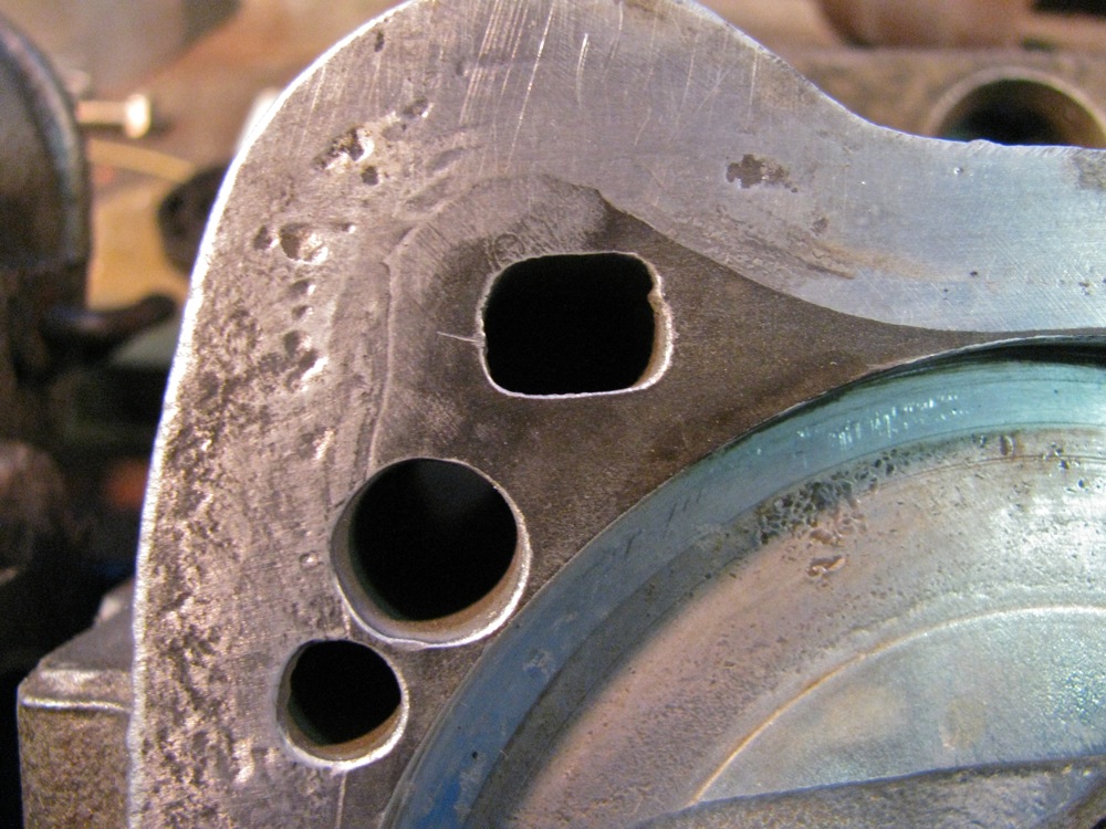
Example exhaust stud.
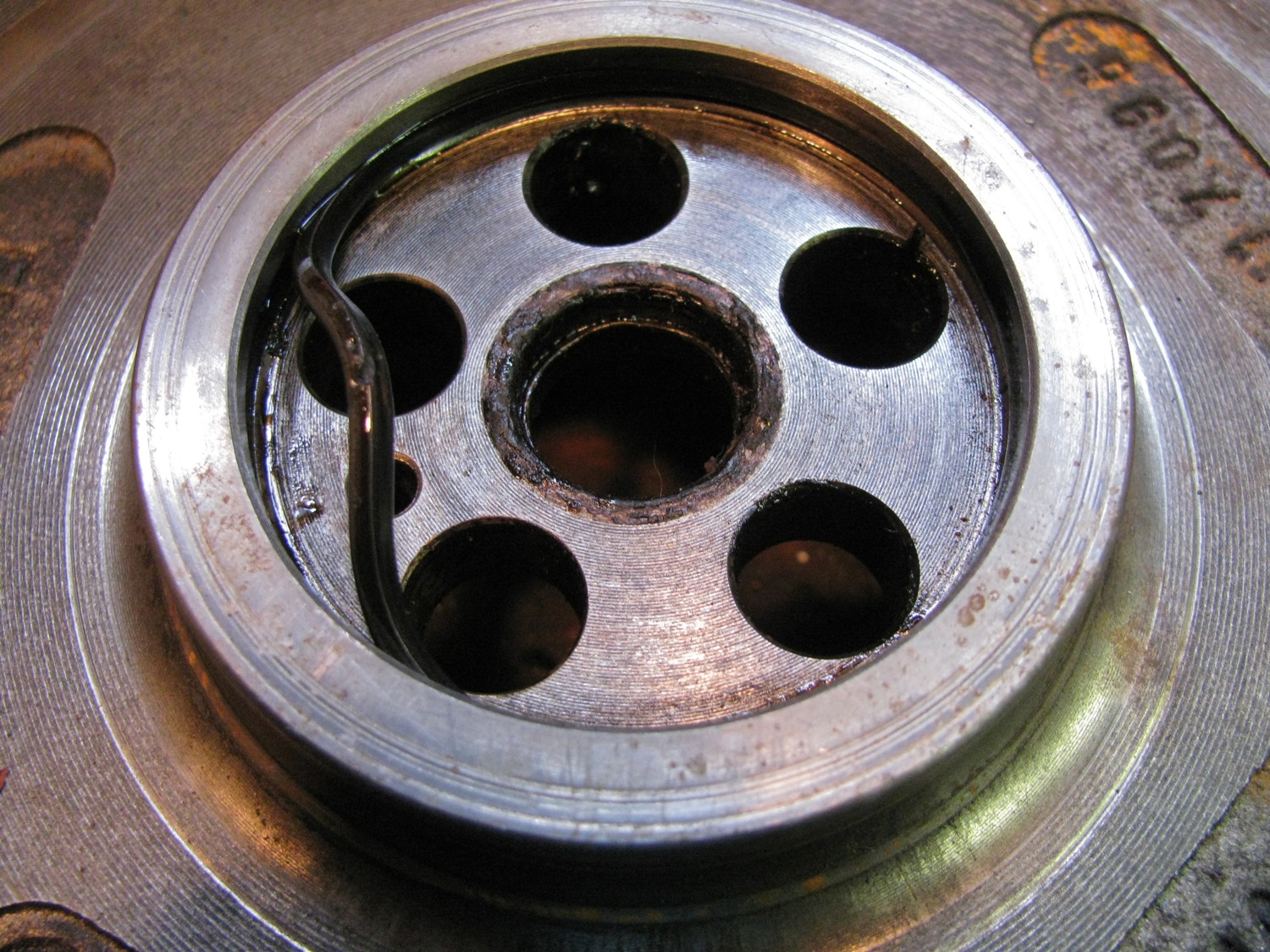
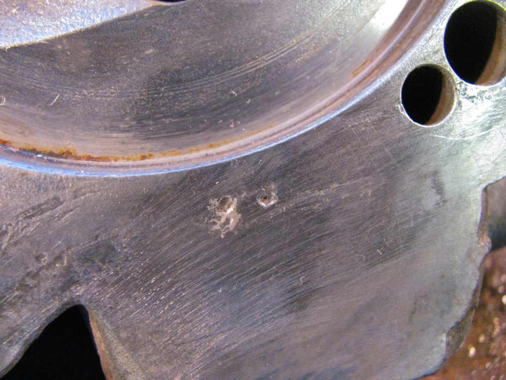
I mentioned previously that I noticed that my water pump was going fast. The pully and shaft was loose, and here you can see how the shaft looseness has allowed the impeller to score the pump body a bit. I don’t think this will affect the function of the new pump too much. BTW, even with the engine on a stand, getting the water pump off is not easy. I would not like to do it on the van.

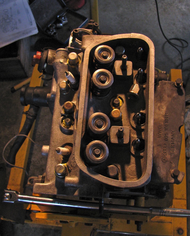
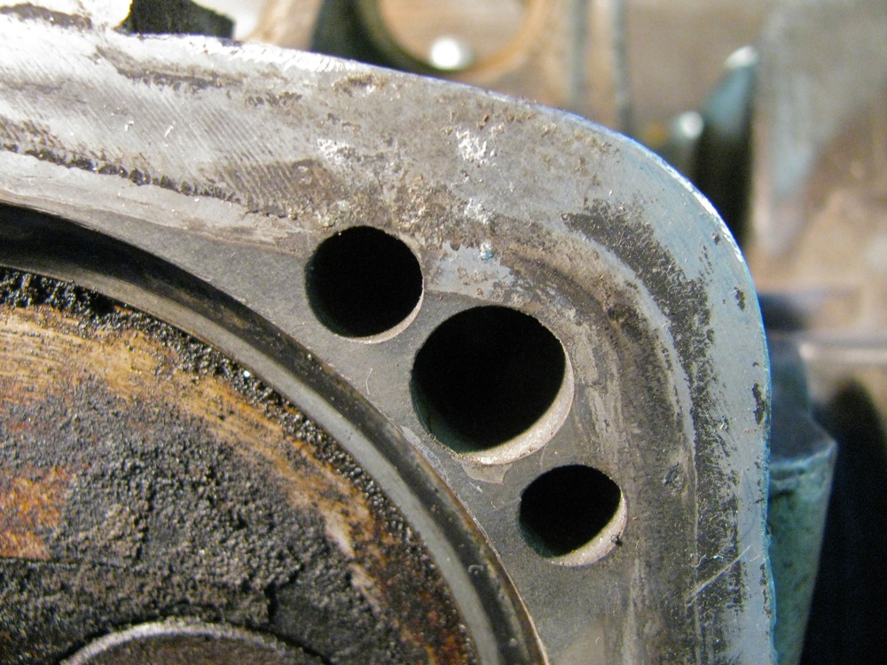
The oily side of the engine. Hello, what’s this? Spring loaded pushrod tubes. I don’t think they worked very well, evidence of oil leakage especially on the one closest to camera.
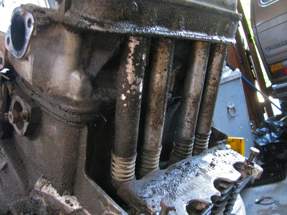
I’ve kept the oil breather tower on during all this, just to cover the hole to the crankcase. I replaced the O-ring at the base of this tower about 2 years ago, but it has been leaking badly. I think I’ll re-install with some oil resistant sealer plus new O-ring.

Another view of that oily head. My god there was a lot of baked on crud to remove. I used a putty knife and old screwdriver to scrape the worst off, then some solvent and brass brush. I wasn’t trying to get the engine pristine, just to be able to work on it without getting angry 🙂

The dry head. Normal pushrod tubes here.

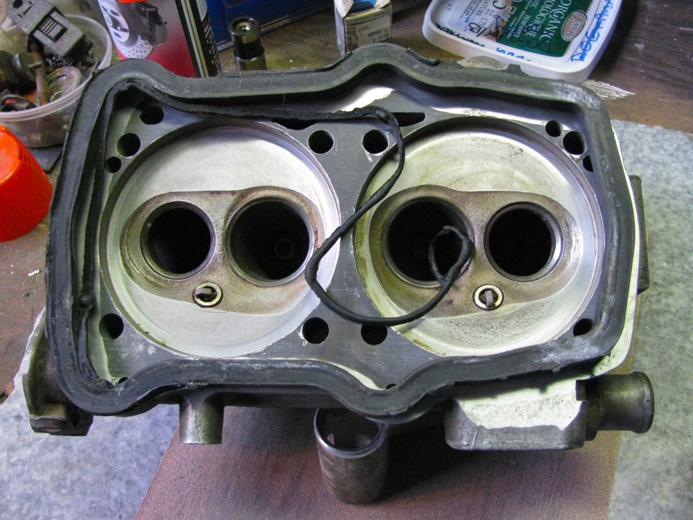
Time to take off a head, starting with the oily one.
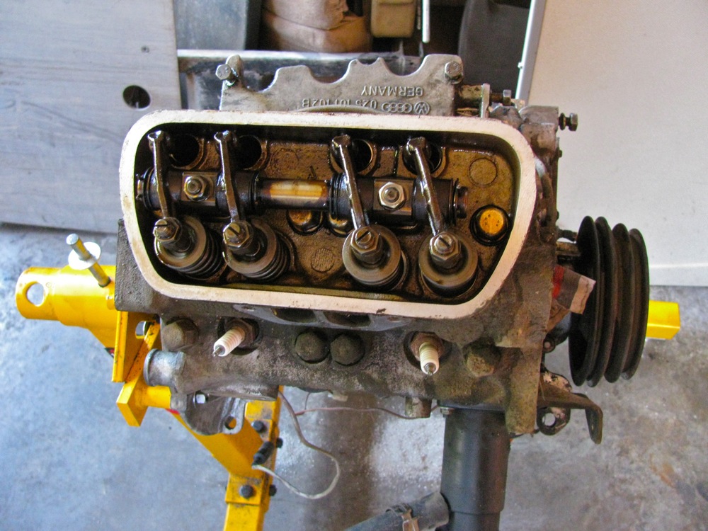
I used some aluminum welding wire and tags to ID the pushrods. Does it *really* matter if they go back int he same hole? I don’t know.
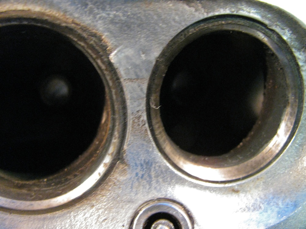
The head nuts removed and the head rapped in various spots with a dead blow mallet. Then I could pry up the head a tad, remove the pushrod tubes and see to my dismay that the cylinders were stuck to the head. It took a fair bit of hitting with a brass drift and hammer to free the cylinders from the head. I only lifted up the head about 7/8″, just enough to get the drift on the cylinders. Prying on those tabs you see in the pic was not effective. I hope the bottom of the cylinders seal again, I believe they do, but… I have the feeling I will pull them and replace the seals down there. Grr.
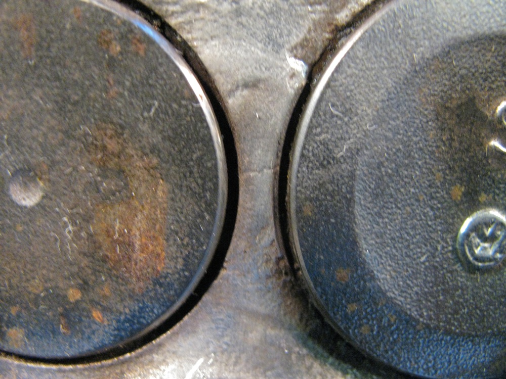
Tops of pistons. I don’t know what normal, good, or bad is supposed to look like. I was happy to see the water jacket edge was not corroded.
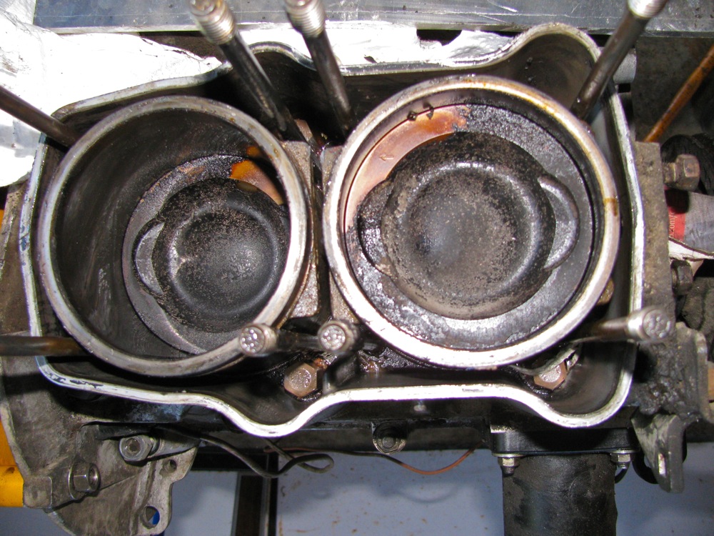
And the head. The black stuff does note really look like sealant. Perhaps it si a mixture of corrosion and Holts Stop Leak. The exhaust valves look different than the ones on my replacement heads. These have a depression in the middle, the others don’t, just a small dimple. Now which type mean sodium filled stems?

Close up of the crud on the head. And do you notice the yellow paint on this head?

Closer look at valves, is that a crack between them?
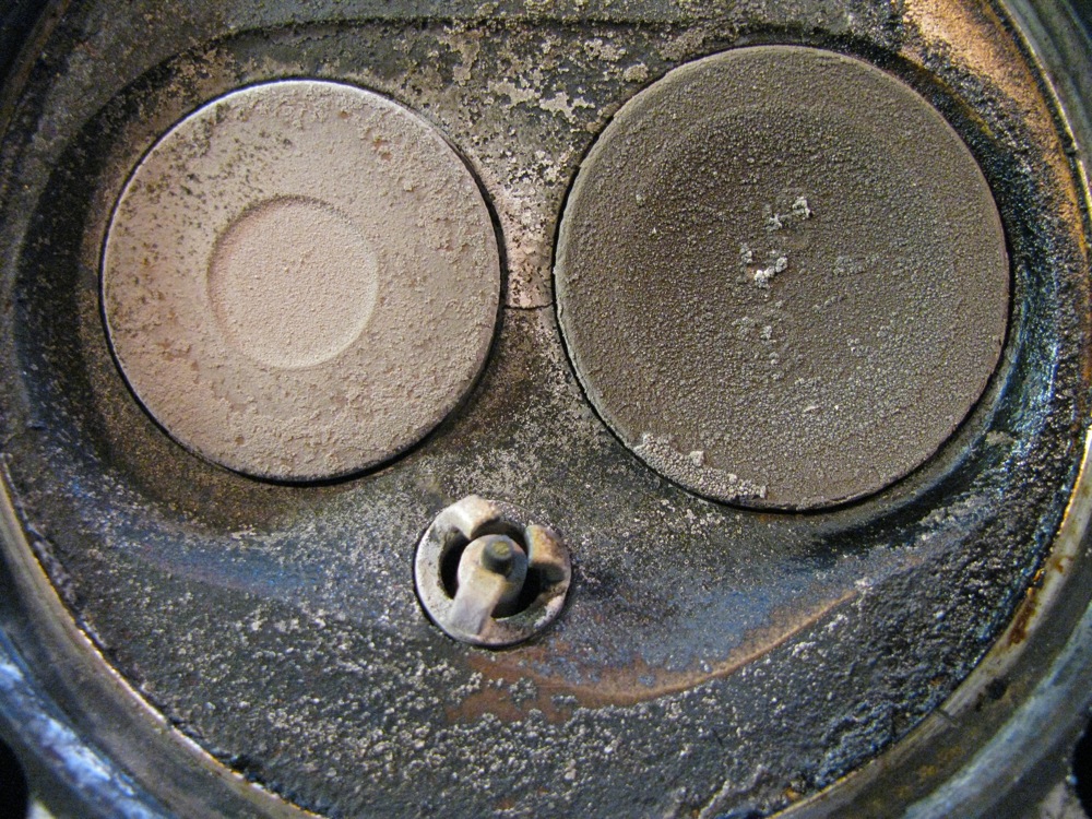
Sure looks like it is.

Well there you have it, today’s work. I’m not getting it done as quickly as I thought I would (doh, when will you learn? Ed.), but it is getting done. Tomorrow I hope to get other head off and then start on the re=assembly. Will be so nice to put some clean parts on the beast.
Vanagon – Q and D* head replacement – engine out
*Quick and Dirty
Took me a while to do it yesterday. I had to clean up some of my mess to make room in the workshop, and I got confused and stalled by what to do with the heat shield that runs across the rear of the engine compartment about the muffler. I didn’t notice right away that the holes in it for the screws holding it to the van were actually slots, not holes. And I had one screw that would not come out (I ended up die grinding the head off). Turns out the shield comes off with the engine – so there is no need to spend time trying to take off the oil filler tube (plastic part does pull off with a little help from heat gun), or to take off the metal coolant pipe that runs from water pump to T-stat. I thought I had to do all that to gain some space rear ward so I could pull the engine back and off the tranny.
What’s that you say? I thought you were pulling tranny and engine as a unit? I did plan on that, then I realised that if I allowed the tranny to drop 4 inches or so (as described in Bentley manual), I could reach the spots on the tranny that I wanted to deal with (starter electrical connections and diff lock light switch). Leaving the tranny in meant I didn’t have to fuss with CV joints or clutch slave cylinder bleeding. But after all the time I spent trying to get the engine back off the tranny I am not sure I saved any time at all.
A couple of other excuses – no lift/hoist and tight working space. Ok, I agree, lame.
Anyway, the dirty oily thing is out and hanging on the hoist (engine was lowered by hoist and pulled out from under van as it was resting on hoist base). Today begins with shop clean up and transferring engine to work stand.
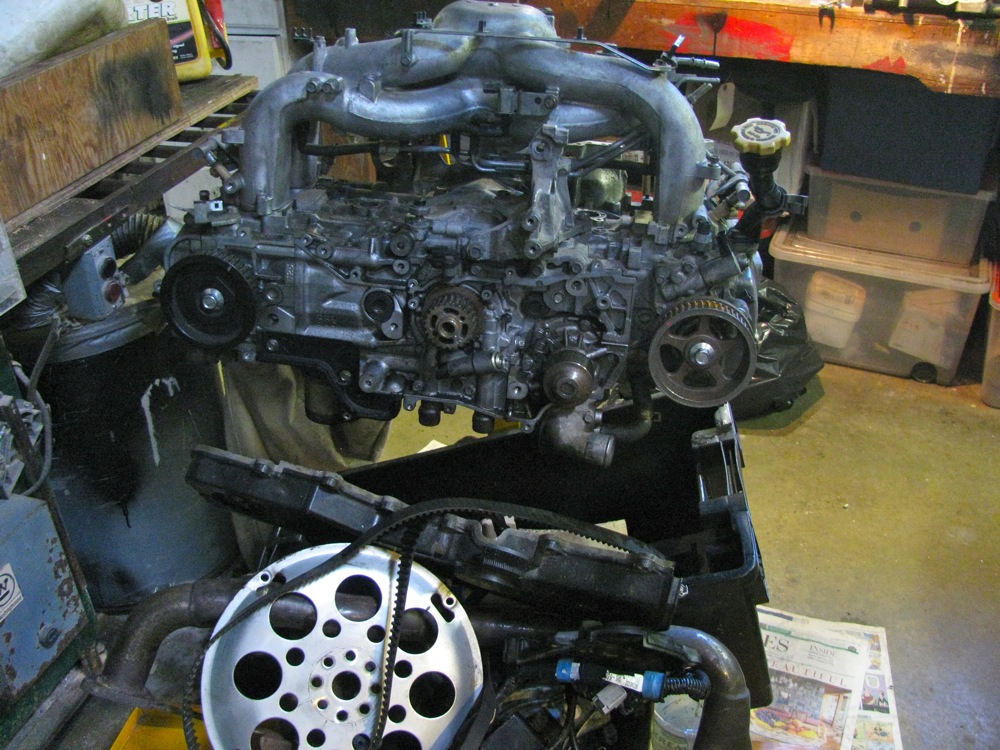
Here is the engine pretty well ready to be removed.
And out.

Tranny is resting on blocks in this shot and van rear is raised high to allow engine to come sliding out. No stress that I could see on tranny connections, but van lowered back down after pic taken. I was concerned about stress on CV joints, but I don’t think I’ve subjected them to any great angle.

Vanagon – quick and dirty head reconditioning
In my last one before last post I mentioned that I had been given a Subie 2.5 engine from good friend Simon. The engine needs to be gone over carefully before using and because I work so slowly and also because I am still not 100% convinced about putting a subie engine in the van (don’t start, I know my feelings are irrational) it won’t be going in my van any time soon. But I need to fix things on my current WBX engine, namely a rotten exhaust and a weeping headgasket (cold weather weep on one side).
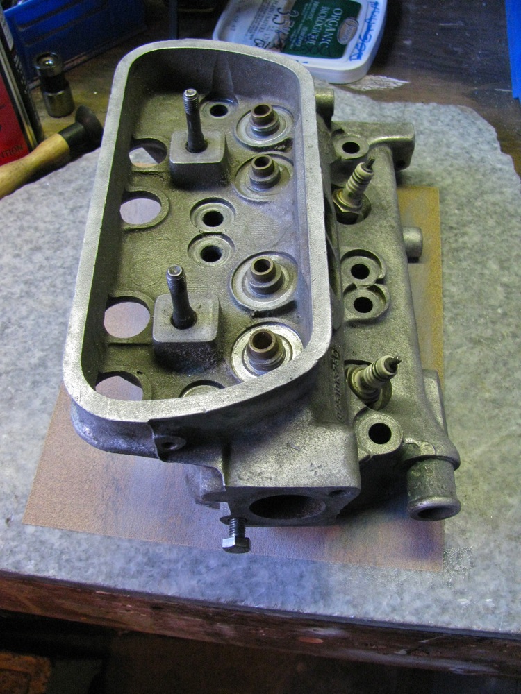
I have a spare WBX, of unknown provenance, and I decided to take the heads from it, clean them up, and pop them on my current WBX. At the same time I can replace the parts of the exhaust system that have rusted away and also replace some seals and gaskets.
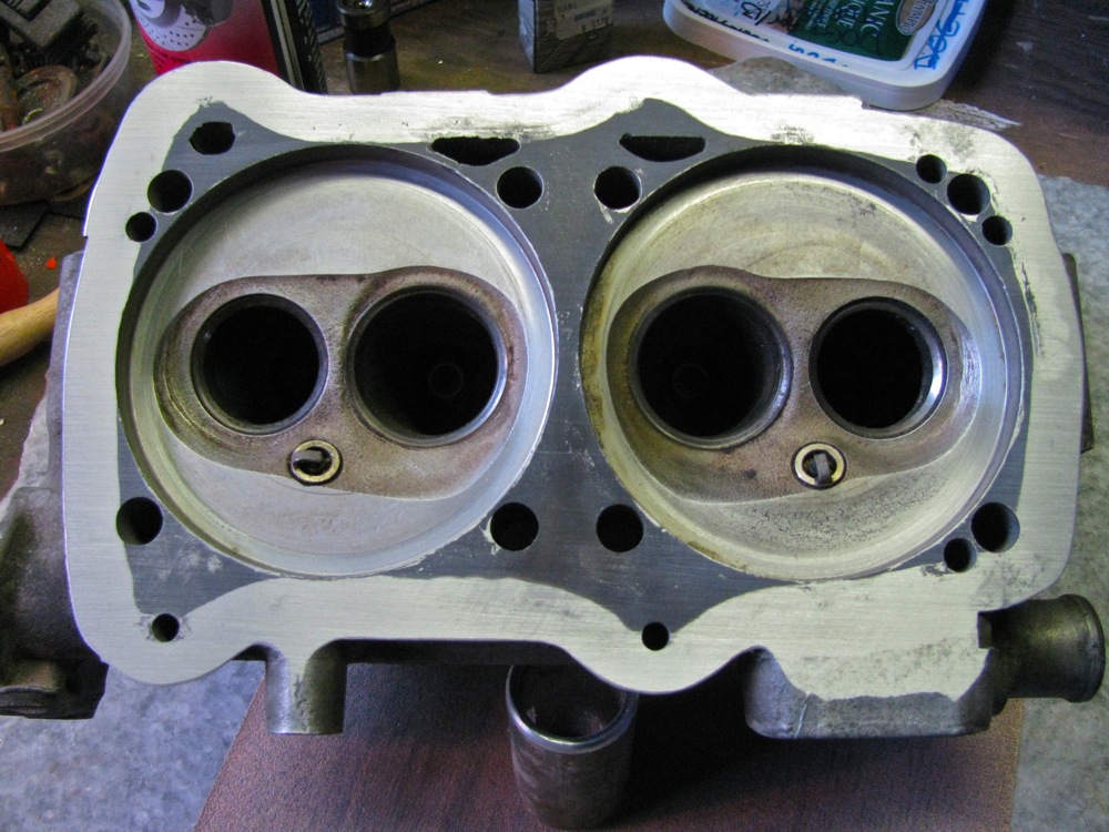
So I took the heads off that spare engine and noted that one head had some pitting and corrosion, the other looked like it was a newish addition. Both heads checked out ok in regards to valves and valve guide tolerance. I set about filling the pitted head with some JB Weld.
Here is the pitted head after a quick fly past with a sand blaster.
JB Weld smeared on the pitted areas.

Head weighted down on parchment paper on a marble slab.

After the JB Weld had cured.

100 grit sandpaper glued to marble slab and head being “lapped”
The result.
All the pits now filled with JB Weld. Even the ones in the pic that still look unfilled.
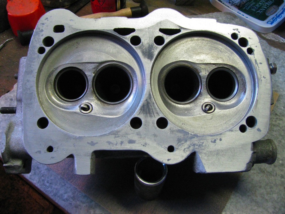
The other head, looking pretty nice.
And with its old gasket. A lot of sealant squeeze out, note that the sealant had blocked hole on upper left hand side.

Gasket flipped, squeeze out apparent, as is the “cast” that blocked the hole, now on the lower left hand side.
I’m taking the rest of the week off work (well work is slow anyway) to drop my engine and tranny and get these heads and the the rest of the needed stuff on.
Vanagon – small finds at the auto wreckers
Posted by albell in vanagon, vanagon mods on May 15, 2013
I had the afternoon off so I drove up to Malahat Autowreckers to see if there were any new Vanagons in stock. And indeed there were, 2 1990 MY passenger vans that were not completely stripped. One was a weekender, driver’s side jump seat and table still intact. Both had something I had not noticed on a Vanagon before, an aluminum sill plate on the sliding door entrance. I bought one, here it is.

The part number is 255 853 558. I think it is available from VW Classic parts, “scuff plate – sill panel- Einstiegleiste”,
Back side:

I also managed to find a couple of undamaged cup holders.

And some fairly new looking front door inside latch plates (they really get ratty, especially the brown ones), and a couple of surrounds.

A few relays and clips rounded out the shopping spree.
Vanagon – misc. updates
Posted by albell in vanagon, vanagon engine swaps, vanagon mods on May 14, 2013
I haven’t been posting much recently, work and garden chores have been taking my time. One good thing about the work time is that my welding is slowly improving. Helps having a good teacher and access to the best equipment. One day I might be able to make a good aluminum weld that is more than one inch long.
But some things are happening on the vanagon front. First off, I replaced the LED light strip on the rear of the lower cabinet, doing away with the pierced moulding experiment. Mainly due to the fact that 6 LED elements failed on the initial install, but also I didn’t like how I drilled the holes. The LED strip is in an anodized aluminum channel


Staying with LEDs, I installed a couple of feet of strip above the footwells of the front seats. They are wired to go on with the doors opening. Not the greatest mod in the world, but fun to do.


When I was younger I thought that ski boxes, or coffins as I dismissively called them, were stupid. But what do you know, I’ve changed my mind and I found a really old school Thule Combi-Box 250 for sale for $50 and I bought it. So why the change of attitude towards these things? In a word, chairs. Yup, I’m fed up with stowing the folding camp chairs behind the back seat. Now they will go up top, and the fishing rods too. I haven’t mounted the box to the van yet, I still have to make some modifications to my roof rack attachments so I can get the box on the right spot on the roof.

The bigger news is that I was given a 2008 Subaru EJ25 motor. Good friend Simon had it in his ’91 syncro and it had been making a brapping clstter upon acceleration. All kinds of things were tried to stop the noise, none of them worked and the final opinion that it was perhaps a rod bearing. So he swapped in another engine and gave me the suspect one.
The generous gift has put me on the spot about future engine transplant. I really have a soft spot for VW inline 4 engines. I had one in my ’82 van (1800 Digifant) that ran flawlessly from 1994 to 2009 (van got T-boned and written off). I’ve been nursing the idea of a 2.0 litre I4 in the syncro. I have all the parts needed except one of the big ones – a diesel gastank. The starter in the 12 ‘o’clock position with the diesel bellhousing so it needs a differently moulded fuel tank to clear the starter. Those tanks are not so common over here on the northwest coast of North America so I haven’t been very quick to get an I4 installed. My dawdling and initial lack of interest in my stock WBX engine has resulted in me not doing much about keeping my current motor in good shape. Bothe the front and rear exhaust manifold need replacement, but the studs.bolts holding them on to the head are really rusted and decayed. I know that they will be hell to remove. Plus I have a slight coolant leak on one head (happens during cold part of winter) so it means some sort of head work even without the exhaust problem.
But then again I have a spare WBX engine that I have been just dicking around with. Why don’t I take the heads off it and see if they are good enough to use on the van’s engine? That way I can replace the exhaust manifold and head leak relatively quickly and keep the WBX in my van running long enough for me to get the Subie engine attended to (or get and I4 built up :)).
I had to drill out a couple of the exhaust studs on the spare heads, nothing, not even oxy-acetylene heat would budge the buggers. One of the drilling out operations went awry and I had to fill the hole by tig welding then re-drill and tap.
So far the heads look usable. One head has pitting, the other does not, just a hint of some corrosion beginning.
The two heads, I took a wire brush to one, and removed one set of valves (valves check out ok, and within spec on fit in valve guides).

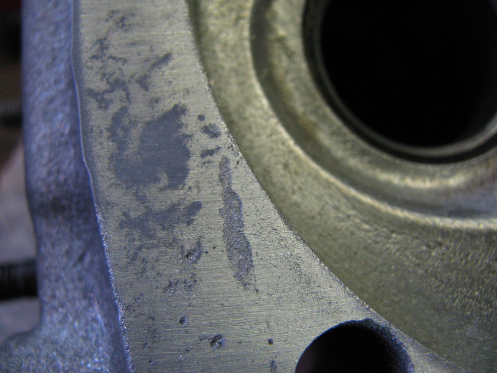
Close ups of the pitted head.
Doesn’t look like any crack between the valve seats.
But is that a casting mark or a closed crack? I don’t think it is anything to be worried about.
The start of some corrosion on the un-pitted head.
And example of what the rest of the sealing surface looks like.

So I’ve got these heads, a gasket kit, a new front exhaust manifold and a used rear manifold. The plan is to drop the engine and tranny (I want to fix the diff lock light switch on the tranny, easier if tranny is out) and swap over the heads etc. I hope to do this in the next couple of weeks.
