It has been a bit of a chore.
I can’t recall if it was last Friday when I updated last, here goes with a catch up of what I did on Saturday. I think it was Saturday, my weekends and evenings are so filled with gallery openings, theatre premiers, cocktail parties, and the occasional orgy that I often lose track of time.
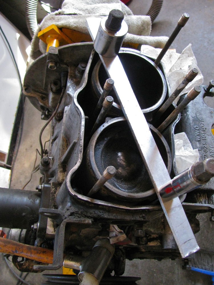
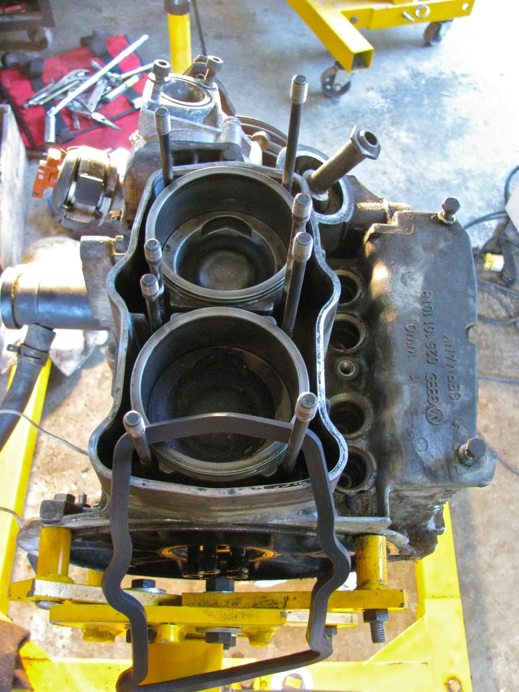
First off, a pic of how I keep the cylinders in place whilst rotating the engine on the stand.
Removing the head from cyls 3 and 4 was difficult. The heads were stuck fast. Lots of tapping with brass drift got #3 loosened, but #4 was a real bugger. I finally got smart and ground the end of my pry bar so it had a sharp edge to catch on the tabs on the cylinder top, final pry and it was free.

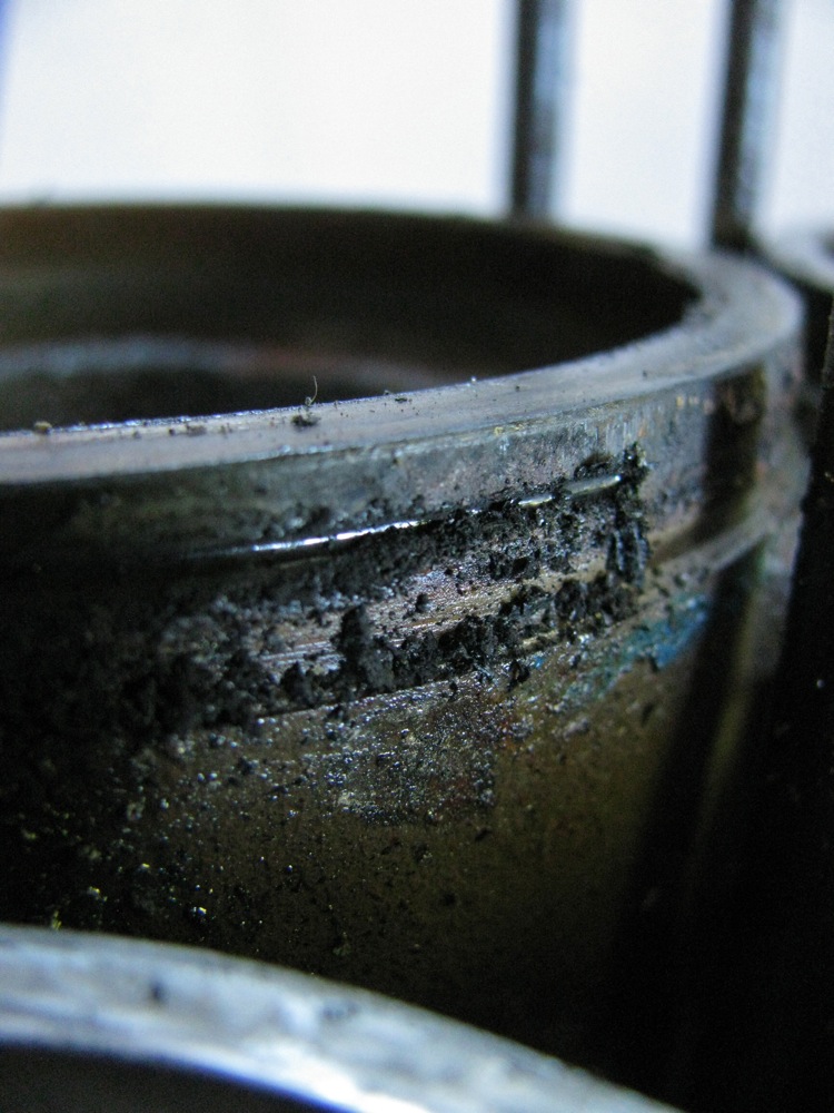
Oh that thin green O-ring at the top of the cylinders, not doing much now eh?

Digging it out (dental pick).
I was getting on fine with the clean up, then disaster struck. I inadvertently, or stupidly (take your pick), pulled #4 cylinder up too far and the bottom (oil) ring came out from the cylinder. “Oh darn it” I said.
Over the next few hours, during which I had no inclination to take any pictures, I pulled the cylinder right off, removed the wrist pin on #4 and took piston out, decided (rashly) to pull #3 cyl too but left that piston on con rod. With them on the bench it was easy to really clean the cylinders. And I was able to clean up #4 piston.
Ok, back to assembling rather than taking more things apart. I used a regular sized ring compressor to get #4 piston and cylinder together. Oh and I cleaned and polished #4 wrist pin, even so it was still a tight fit.
I cut down another of my ring compressors so that the compressing band was about 5 mm wider than the distance from top to bottom piston rings. This particular spring compressor could be taken apart. The head bolts and water jacket restricts access to #3 piston even with #4 piston and cylinder removed, bit the compressor worked like a champ and I got the cylinder over the piston first try.
But… when I was removing ring compressor a part of it fell into the open spigot of #4. “Oh gosh darn it”. The piece was aluminum and my Al magnet was at work. Rotating the engine didn’t work. I finally pulled #3 cylinder again and the lost part was tucked under the piston skirt.
Ok, again, cylinder back on, compressor removed very carefully, then the assembled (on bench) #4 piston and cyl brought over to do the gynecological insertion of wrist pin through water pump and into (flopping around) con rod. VW has a special tool to hole the cond rod in place, but I did it by getting the engine rotated on stand “just right” so con rod hung in position.
Phew!
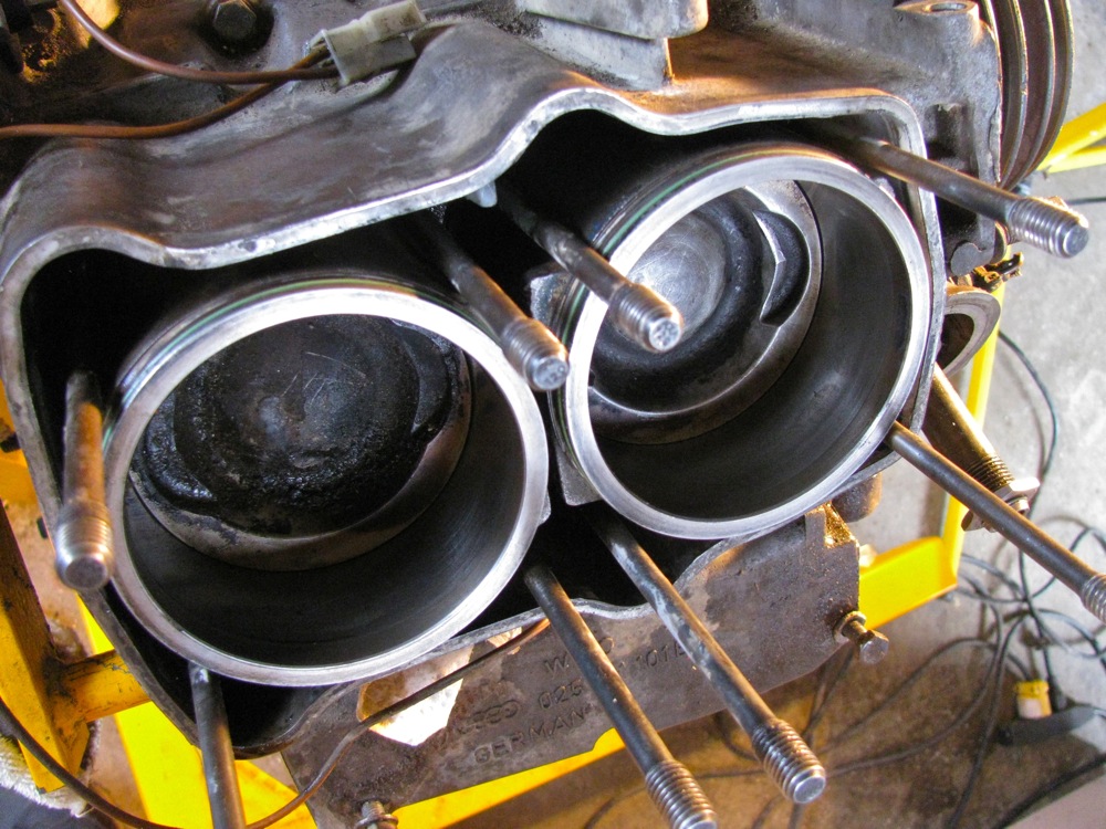
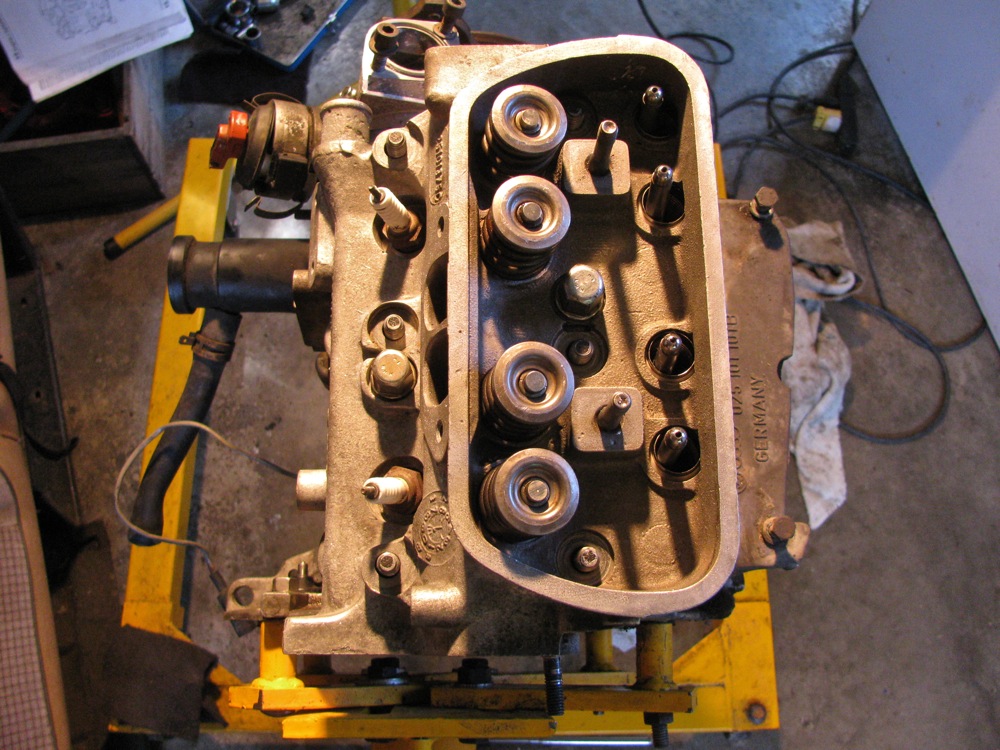
Pic taken just before all that.

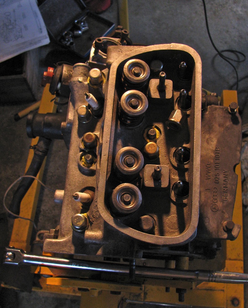
And after things back together. Also replaced black O-rings at bottom of both cylinders.
Back on the heads, using a spare cylinder I “lapped” where the cylinder meets the head.

Fine carborundum powder, oil, and twisting the cylinder back and forth. Then I cleaned up the heads, blasted with compressed air, re-installed valves (gave them a little lap love too), then degreased the surface where the rubber gasket seals.

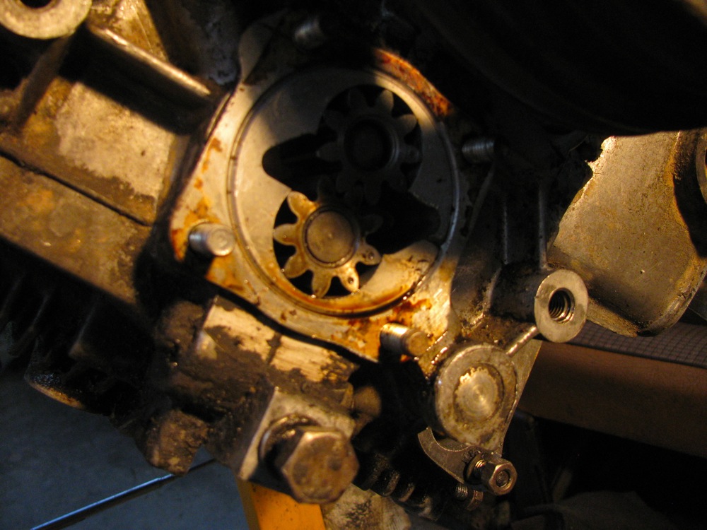
Then on to the oil pump. What stalled me here was trying to remove all of the old paper gasket. The paper was really stuck on and one did not want to scratch up the mating surface. The endplay on the pump measure out to 0.002″ (wear limit is 0.004″) so I decided to use the new thin gasket during re-assembly. Some say to use just some sealant if endplay is close to wear limit. I lapped the pump cover to remove the pump score marks, don’t know how useful that is.
And now the rubber gasket. I used the Reinzosil sealant that came in the gasket rather than “The Right Stuff” (and I do have a tube of that). Why? Well why not? All accounts are that it is good stuff, improved from the original. A thin bead applied to the grooved side of seal and the seal placed on the water jacket. Then a thin bead down the centre of the mating surface.

Then the head….
Cleaned up pushrod tubes, checked them for length so they would have good “push” when compressed, put on new seals. Clean and dry holes in case and head.
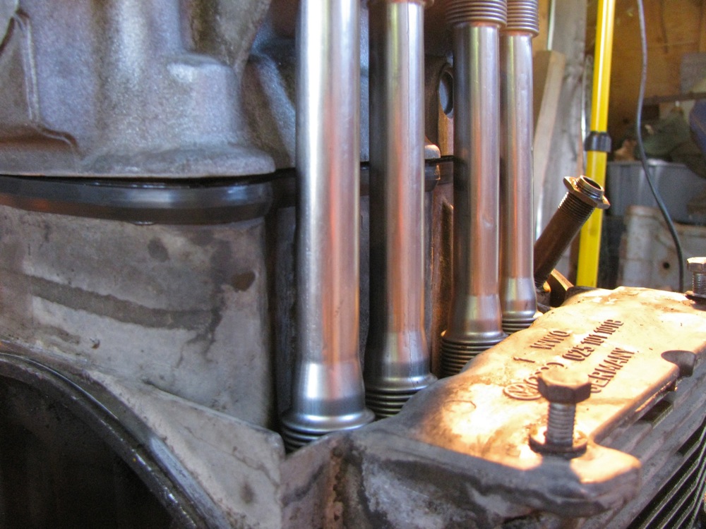
I used cap nuts on 2 centre bolts to pull the head down (compressing pushrod tubes) enough to get the rest of the cap nuts on. Yellow sealant applied to the head rather than the base of the nuts. It all went rather easily. Torqued the head down in 3 stages – 10, 25, and finally 40 ft/lbs.
I numbered the cap nuts in torquing down sequence. I was nervous, numbering the caps calmed me down 🙂

And I got the other head on with no drama. I had to check the fit of my new exhaust manifold (Dansk) and it fit up to the heads as if it was made for the job.

Then I started putting things back on. A cleaned up, inside and out, breather tower with new O-ring, new waterpump, and one newly painted coolant pipe.

Enough for this post, I’ll try and catch up on my progress in next post.

#1 by famillysyncro on May 27, 2013 - 8:49 am
Yes you are winning.
Amazing job, I am pretty sure your engine is ready for another 100,000kms after that.
Not sure about the other head if you reused those spring loaded pushrod tubes or if you had a set of regular model?
Anyway, good job as usual.
Jerome
#2 by albell on May 27, 2013 - 9:45 am
Thanks Jerome. I admit to feeling very unsure about the whole thing as I was doing it. Been years since I have done anything like this, and I kept thinking I should split the case and look at bearings etc etc.
I hope my rod bolts hold up for a while longer 🙂
I used “new” regular push rod tubes, from my spare engine. They were in great shape, almost think they are made from stainless steel (could this be? I’ll check with magnet). The spring loaded ones are well made, machined aluminum. But they are sticky, don’t have a smooth action.
I came across a couple of minor speedbumps. One just annoying, the other was something I am damn lucky to have discovered. Will be in next blog post.
cheers
ab
#3 by edbee on May 27, 2013 - 9:27 am
Nice work, though makes me happy I chose to replace my waterboxer. I have never taken apart a flat VW engine and I guess I never will… but nice to do it vicariously… 🙂
#4 by albell on May 27, 2013 - 9:46 am
Ed,
I’m liking the I4 more and more as I work on the boxer. Mind you, for all the bad press the WBX gets, I’m impressed by the construction.
Nice work getting your van moving Ed.
cheers
ab
#5 by Bosnaexpress on May 27, 2013 - 3:35 pm
you are a hero!luv your work around the syncro
#6 by albell on May 27, 2013 - 3:51 pm
more fool than hero I think. 🙂
cheers
alistair
#7 by Joel on May 27, 2013 - 8:57 pm
All this fine and much appreciated documentation of the rebuild must cut into your orgy time :-), I hope you get more that 100 K out of the rebuild, or is that the expectation when you go out and climb hills with your syncro?
Looks great and I like the detailed photos.
Thanks!
llmamaman
#8 by albell on May 27, 2013 - 9:32 pm
Thanks Joel,
I could have done a lot better in documenting with pics and text, but I figured others (Ben’s place) and the Bentley manual have that covered well. I just take pics and mention things that are of interest to me, selfish bugger that I am.
cheers
ab