Archive for June, 2010
Syncro Westy – rust treatment and Zetec engine
Posted by albell in syncro, syncro specific repairs on June 29, 2010
Whereas I just poke around the fringes of syncro repair, Ed In Vancouver goes deep with rust repair and a Ford Zetec engine swap. His website is here.
Westy sink p-trap
Posted by albell in vanagon mods on June 27, 2010
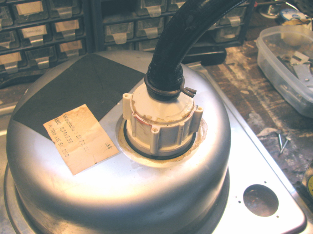
I have the cabinets out of my ’82 westy and while moving the sink/stove top I carelessly broke off the hose barb that connects the sink drain hose. I had replaced that part years ago after i broke it the first time, this time I decided I didn’t need a p-trap on the sink. Why do you need a p-trap there, eh?
I took the trap assembly off (4 screws and a gasket) and I connected the drain hose directly to the sink drain “spout”. That spout is still made of the suspect brittle plastic but try as I might, I could not unscrew the plastic from the stainless sink. Heating the drain hose, which by the way is 28 inches long, with a heat gun allowed me to get the hose over that spout, and secure with spring type hose clamp. Its not a barbed spout, but the hose is on there pretty darn tight.

Home made steering rack bushings
Posted by albell in vanagon mods on June 27, 2010
All my talk about rubber mounts reminded me of this neat home made solution to steering rack movement. I had this posted on my web site, thought I ‘d put a copy here too.
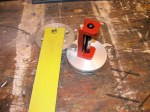
Gary Stearns’ method of how to make your own polyurethane bushing to replace the slopy or worn out stock units.
Gary writes:
“Attached is a bitmap of drawings that I made of these bushings and their installation. The one’s that I started with came from Autozone and were sold as anti-roll bar bushings in a pack of eight.
I was able to get the bushings in and out without removing the rack completely, but it’s not easy. To permit “test fits”, you might want to take the rack out; I’ve done that too and it’s not as difficult as you might think. ”

Front diff. mounts – anomaly
Posted by albell in syncro specific repairs on June 22, 2010
Update: Well I got wrong info, there never was a spacer on front mount. In fact the tabs on the plastic spacer will not fit into mounting hole on the front mount.
I recently posted how I looked at the front diff. mounts and discovered that the foremost one had slightly distorted rubber mounts. What I did not realise was that some syncros have plastic spacers on those mounts too. Mine did not. A quick survey on the syncro and the vanagon mailing lists only returned one other owner (also an ’86 van) that did not have those spacers installed in the front mount. The parts catalogue shows none of the front diff. mounts having spacers, but do list them on the side, and 4 needed (4 would be enough for only the 2 rearmost mounts) You can see at least the rearmost ones with spacers in the Bentley manual. The part number is 251 199 399 , its the same plastic spacer that is found the transmission mount. I decided to try and make a spacer(s) and found a scrap of polyethylene cutting board that was big enough to make a reasonable copy. I just need to make another then install and see what difference it makes in the front diff. flange angle saga.
Here is a diagram of the transmission mount arrangement, the spacer, #9 is the one in question
![]()
And here is a diagram of the front diff. mount arrangement, note absence of spacer in all 3 mounts.

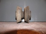
And here is the spacer with my cutting board copy (note flats on sides of my copy, the scrap bit was not quite large enough)

If there is anyone out there interested enough to have a look at their own syncro front diff front mount and report back presence or absence of spacer, I’d be very grateful.
Better measurements of flange angles
Posted by albell in syncro specific repairs on June 20, 2010
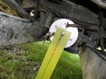
Took my time with my revised laser thingy and measured front diff and transmission flange angles. The pictures show the process. Laser on flange, measuring jig on other flange. I added a plumb bob to measuring jig to be sure it was plumb so that any lateral misalignment would show up (you can see the string in the pics). As it turned out there is very little sideways error in flange orientation. I remeasured the flange centre to centre distance as 1820 mm, and the vertical measurements are as follows:
Laser on transmission – dot 103 mm below centre of front diff. flange. This works out to be a 4.6 degree angle on the trans. flange.
Laser on front diff. – dot 83 mm below trans. flange. This works out to be a 3.7 degree angle on the front diff. flange.
The numbers are close to what I measured before, but I feel confident in these measurements. In the pictures the laser dot size seems larger than real life, and in one shot you can see the laser beam itself. The CCD in the camera must be sensitive to the wavelength of the laser.
Note: picture showing measuring stick on front flange and dot around the #8 mark is actually showing an erroneous first try, I had a bit of “schmumf” stuck between laser and flange, second try had dot further down measuring stick, and that is shown in close up pic.


Fastener info and reference
Posted by albell in Uncategorized on June 17, 2010
Nuts and bolts and screws and washers and…
Good reference document, pdf.
fastener manual
Mark III laser thingy
Posted by albell in syncro specific repairs on June 17, 2010
Not being happy with how the laser pointer was held in the jig, I finally did what I should have done all along and that is use the laser’s own mounting bracket. The bit of aluminium angle bolted to the round jig gets clamped by the red bracket’s captured screws (not visible in pic). Now I can adjust the beam so that it is pretty well aligned with centre of jig. Previously the best I could do was a 1 cm circle, over the 1.285 m between flanges, when jig rotated on flange. The thing on the left is the crude reference jig that sticks onto the the flange opposite and shows the laser dot.

Again with the prop shaft
Posted by albell in syncro specific repairs on June 15, 2010
My last posts showed how the transmission flange is pointing down at a steeper angle than the front diff flange. I could not see a way of easily changing the transmission angle so I decided to shift the front diff. I supported the diff with a bottle jack and took off the front carrier and the rubber mount. You can see where the mounts go in the diagram, (No. 6). Looking at the mounts, I could see the lower mount was squished a bit.


So I swapped the thicker, or less collapsed top mount with the lower mount, and I added a couple of washers for good measure to help lift the front of the diff. so that the rear, where the flange is, would point down more.
I did a quick measurement with the Beall Angle Box, and the flanges were within half a degree of each other. My laser thingy showed that the angle had indeed changed, calculated out at approx. 0.65 degree difference…but I am not confident in my measurements. The electronic angle finder is sensitive to how it is placed on the flange and the laser pointer is not perfectly fitted at 90 degrees to the base so that it scribes a 1 cm circle when rotated. I have to refine my methods, but its close enough for the time being.
So I put the drive shaft in and took the van for a drive…. still a slight vibration at 50 kph (mind you, it is less than before). I left the bolts on the 2 rear most rubber mounts of the front diff. loose, wondering if the diff will find its happy spot during driving. No such luck. Will try again but with yoke bolts loose. Next “major” step is to go over lateral alignment.
