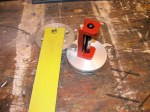
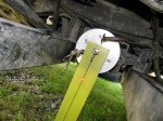
Took my time with my revised laser thingy and measured front diff and transmission flange angles. The pictures show the process. Laser on flange, measuring jig on other flange. I added a plumb bob to measuring jig to be sure it was plumb so that any lateral misalignment would show up (you can see the string in the pics). As it turned out there is very little sideways error in flange orientation. I remeasured the flange centre to centre distance as 1820 mm, and the vertical measurements are as follows:
Laser on transmission – dot 103 mm below centre of front diff. flange. This works out to be a 4.6 degree angle on the trans. flange.
Laser on front diff. – dot 83 mm below trans. flange. This works out to be a 3.7 degree angle on the front diff. flange.
The numbers are close to what I measured before, but I feel confident in these measurements. In the pictures the laser dot size seems larger than real life, and in one shot you can see the laser beam itself. The CCD in the camera must be sensitive to the wavelength of the laser.
Note: picture showing measuring stick on front flange and dot around the #8 mark is actually showing an erroneous first try, I had a bit of “schmumf” stuck between laser and flange, second try had dot further down measuring stick, and that is shown in close up pic.