I’ve been amusing myself (!) by attempting to make a latch for the swing away tire carrier that’s going on my aluminum bumper. I have this almost unreasonable desire to make sure the horizontal arm of the carrier is fixed hard against a back stop on the bumper. I know other designs use an over the centre draw latch mechanism, and I am sure they work well. But I got in my head that I wanted to try another approach.
The back stop mentioned will be a sturdy bit of aluminum plate welded vertically to the forward top edge of the bumper. Something like a 4″ X 6″ bit of 3/8″ plate. It will be positioned at a point on the bumper were the end of the swing arm end up when the arm is “closed”. Now imagine a truncated cone projecting horizontally back from that plate that fits into it’s female mate that is in the swing arm. The cone arrangement will, I think, locate and secure the arm to the back stop.
Instead of a draw latch I decided to have a captured screw handle on the swing arm. This screw handle will engage a threaded rod projecting out from the male cone.
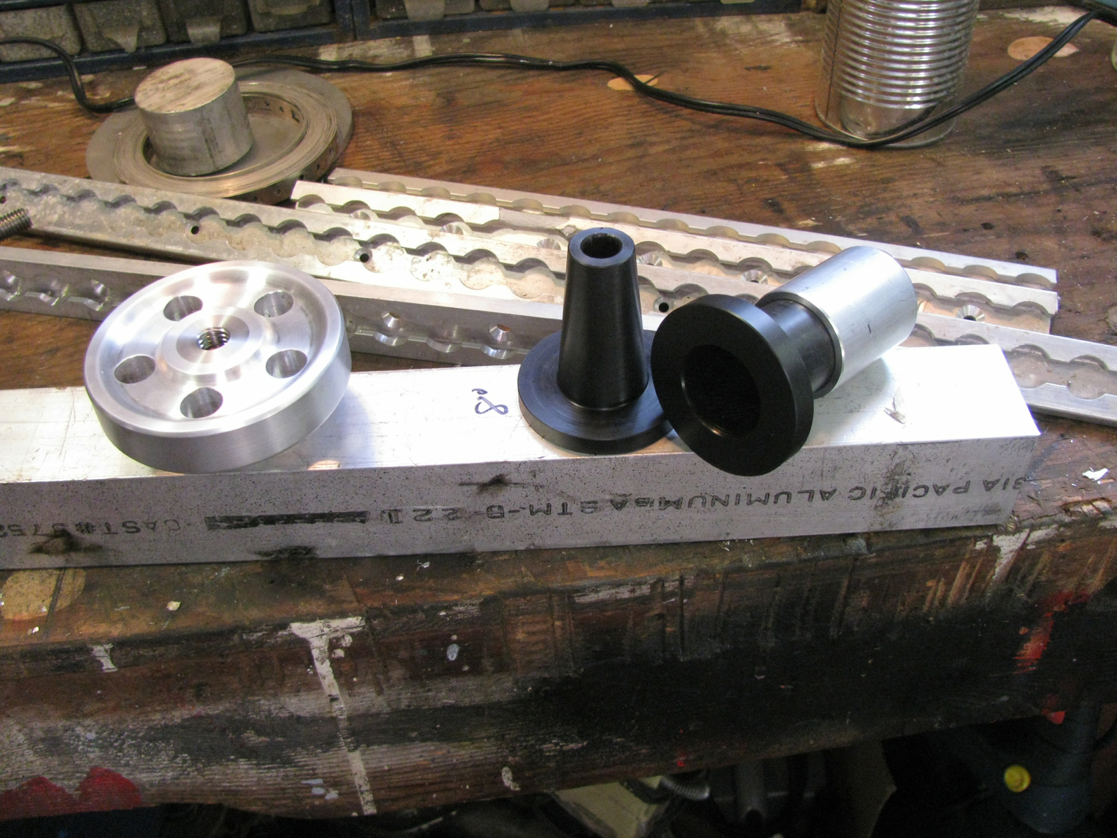
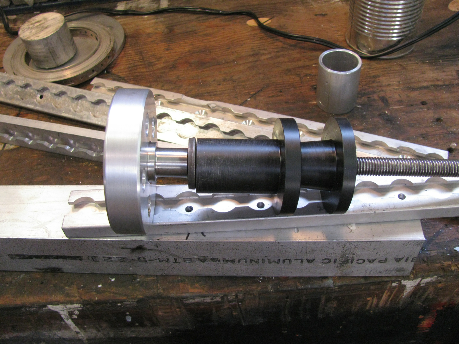
Yeah, it doesn’t seem very clear and I don’t have a sketch of my idea. But here are the parts I have made so far.
From left to right: hand wheel/screw handle, male cone (will be attached to back stop), female cone partially inserted into bit of tubing that will be welded into the swing arm.
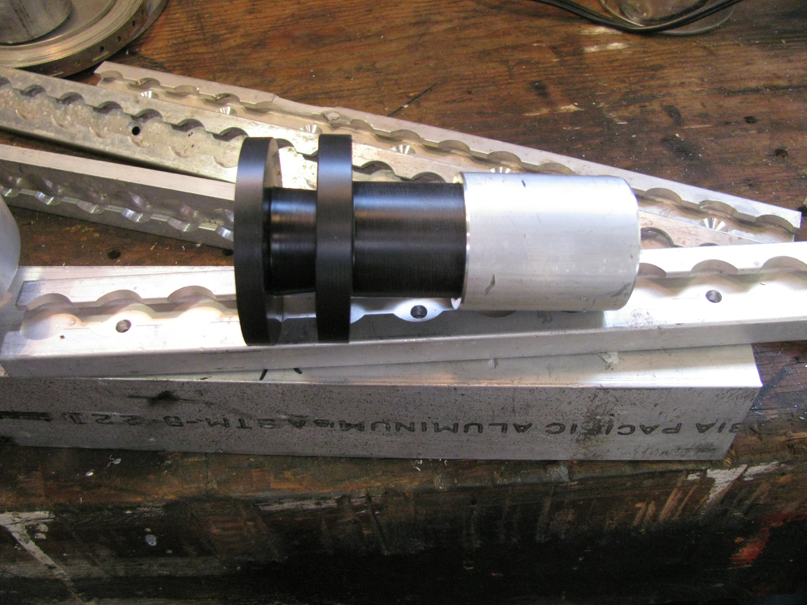
The cone couple. 10 degree included angle, made from Delrin. It is a tight fit into the aluminum tube that will house the female cone. A bit of glue and a couple of countersunk screws on the flange will hold the Delrin in the aluminum.
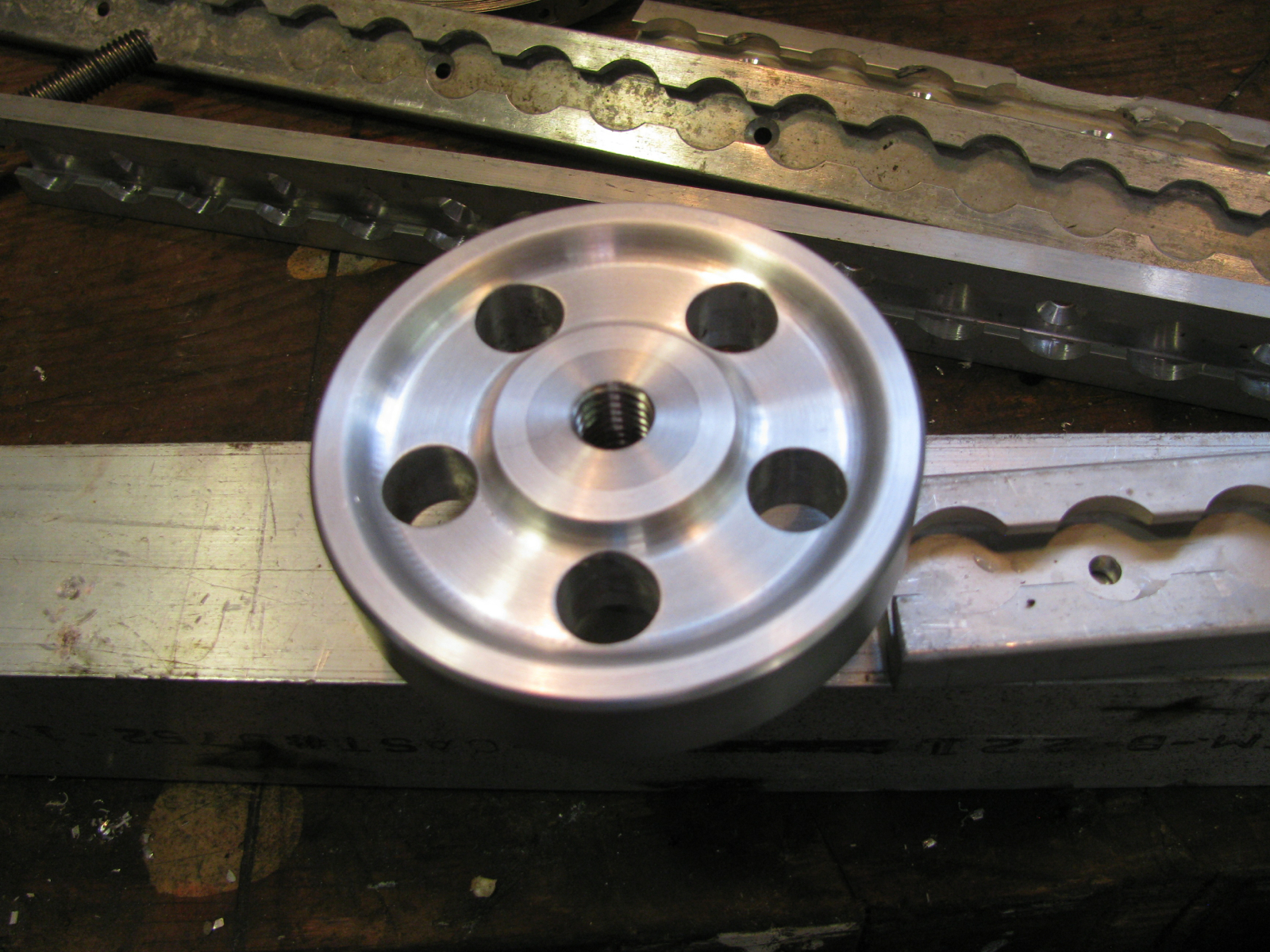
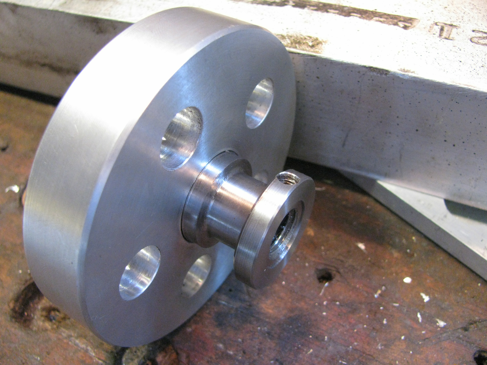
The hand wheel (going to call it that from now on) is made from scrap aluminum with a centre section of stainless steel pressed in. I mean really pressed in, a shrink fit. I heated the aluminum and drove the stainless into, the somewhat enlarged by heat, hole. Then I fancied it up with a turned recess and some holes. The stainless centre is threaded for 1/2″ NC.
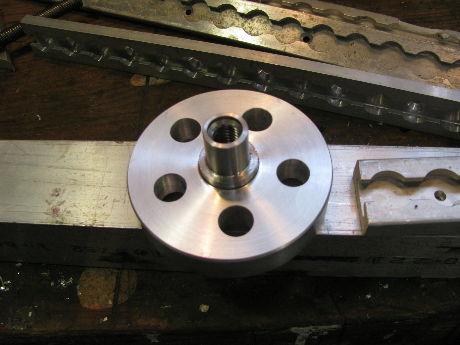
The other side. The narrow section will be inside the “cage” that I have yet to make that will hold the hand wheel to the swing arm.
Arranged in order.
I had to make a collar to put on the narrow portion of the hand wheel to stop it falling out of the cage when unscrewed from the threaded rod. Of course I broke the damned tap when i was threading a set screw hole.
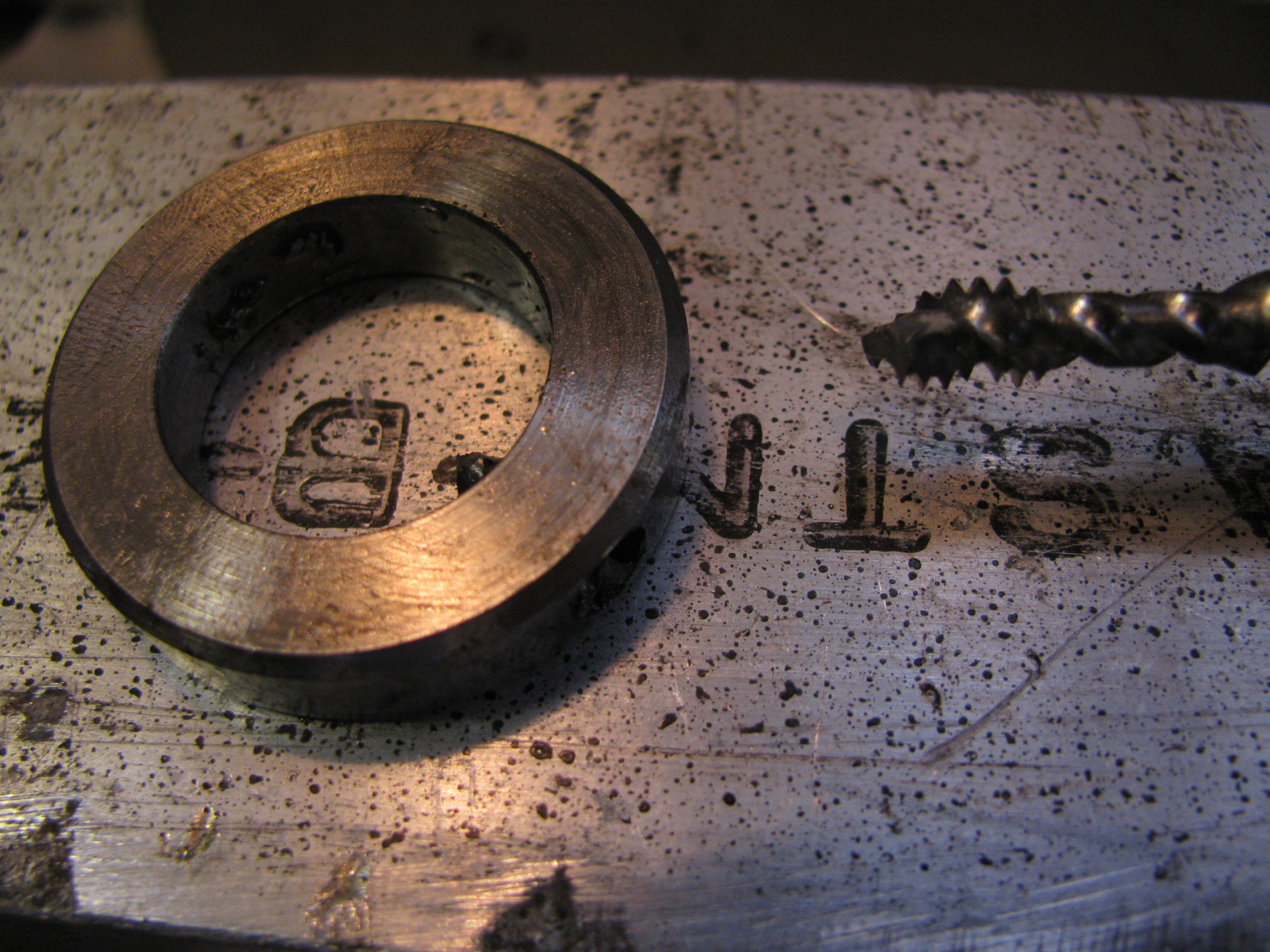
Grr.
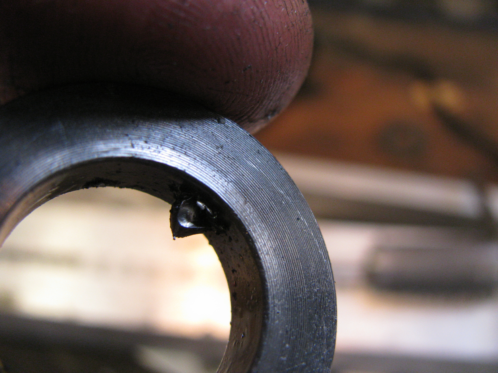
I didn’t want to make another collar so i ground down the stuck tap (carbide burr on die grinder) and drilled for another set screw.
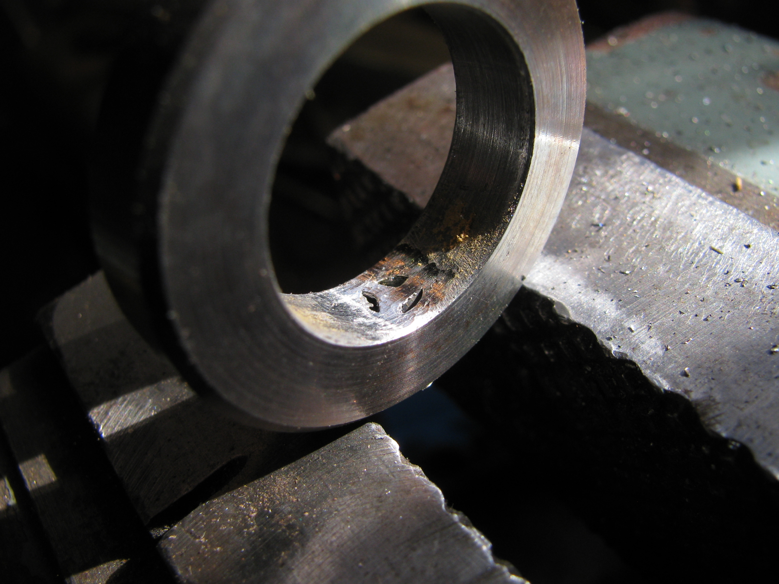
I was so pissed that i broke a tap I didn’t get the new hole exactly centred on the collar. Too bad, thats the way it is.
Enough of this for today.

#1 by Angus on February 19, 2014 - 5:13 pm
Looks interesting!
What’s with the seat/cargo tracks?
#2 by albell on February 19, 2014 - 5:20 pm
Interesting is right Angus. I figure why not try something different, if it fails I can hang my head and make a draw latch like everyone else does.
Found the seat tracks at the scrapyard the other day. I think it might be Viking air scrap. Good friend Simon will get some of it, to go on the outside rear of his high top.
I need to find the tie down fixin’s though
Cheers
Ab
>