Archive for category syncro specific repairs
Vanagon – cooling system leak
Posted by albell in syncro, syncro specific repairs, vanagon on April 20, 2012
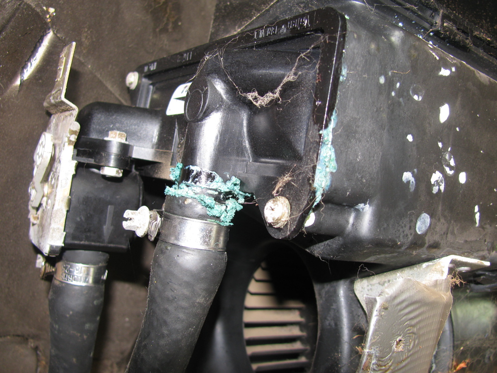
Bloody vans eh? No sooner than I fixed that wheel bearing than another problem bites me. Last couple of days I had been noticing a slight whiff of coolant when I got out of the van. I couldn’t see any leaks, inside or out. Then yesterday I noticed that my coolant overflow tank was empty and even I could not ignore the fact that I had a real live leak somewhere. I topped up the tank and fretted about expensive repairs. Today after a short drive, the smell was much more pronounced and I did find the leak. Thank the Vanagon gods that it was a hose leak, short section that runs from the thermostat to the lower of the two crossover pipes at the front end of the engine.
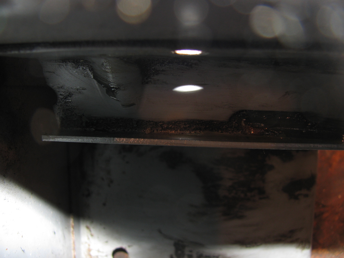
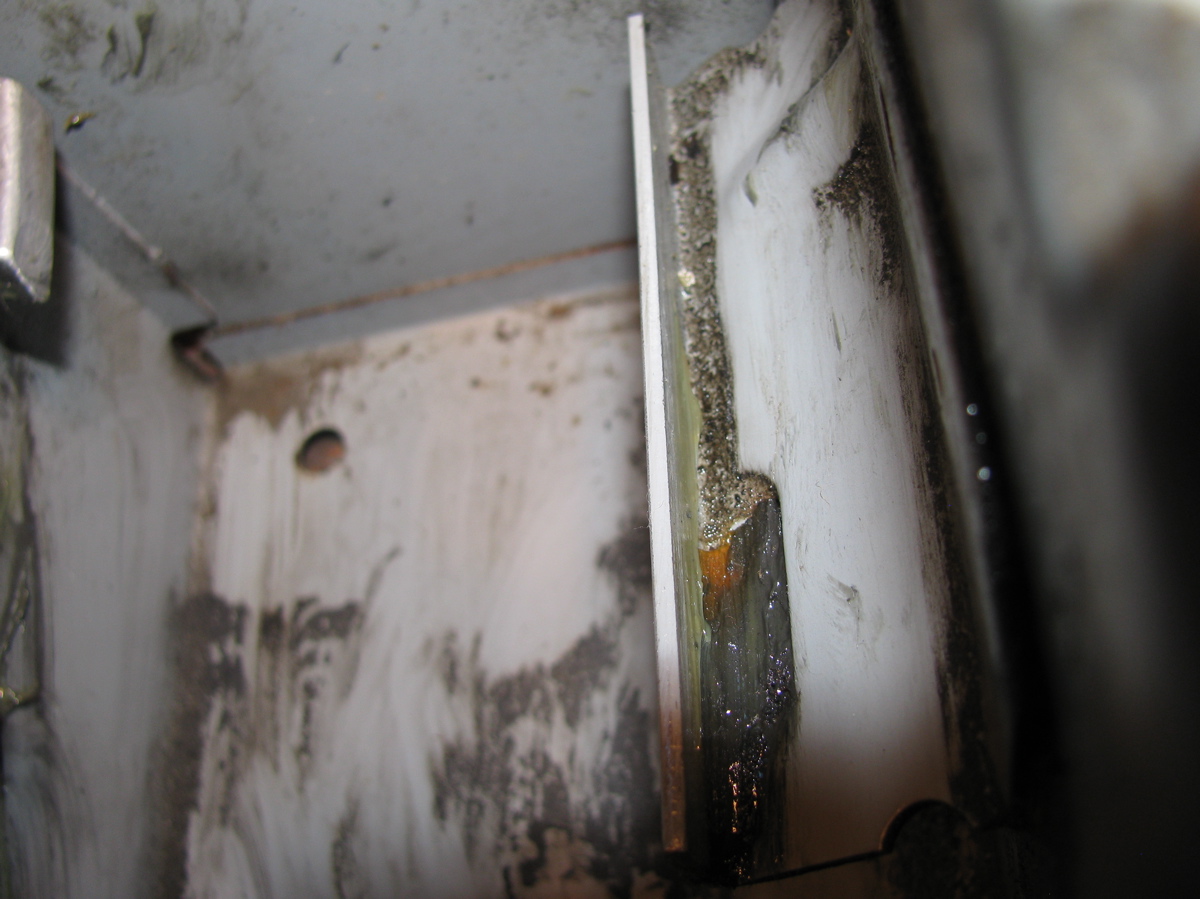
This pic from above does not show any wetness (the bad hose is the lower, thick one). Update: I think it is this hose featured at Van Cafe.

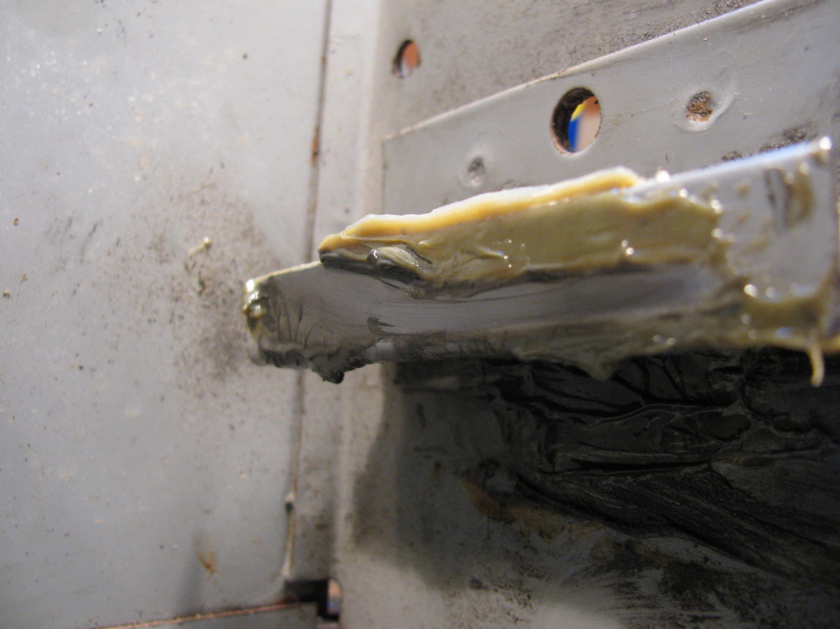
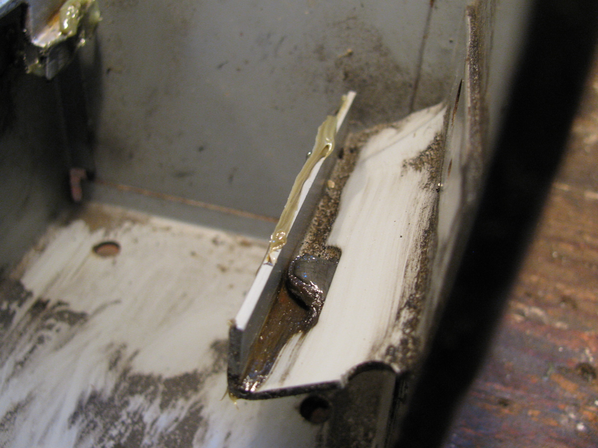
But from below, you can see the marks of a leak.


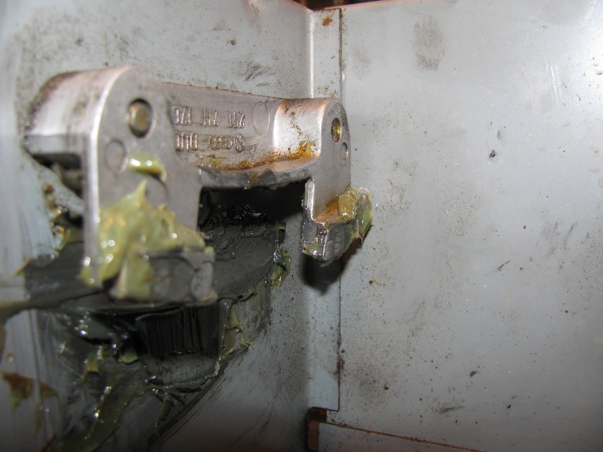
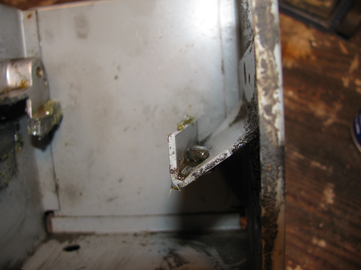
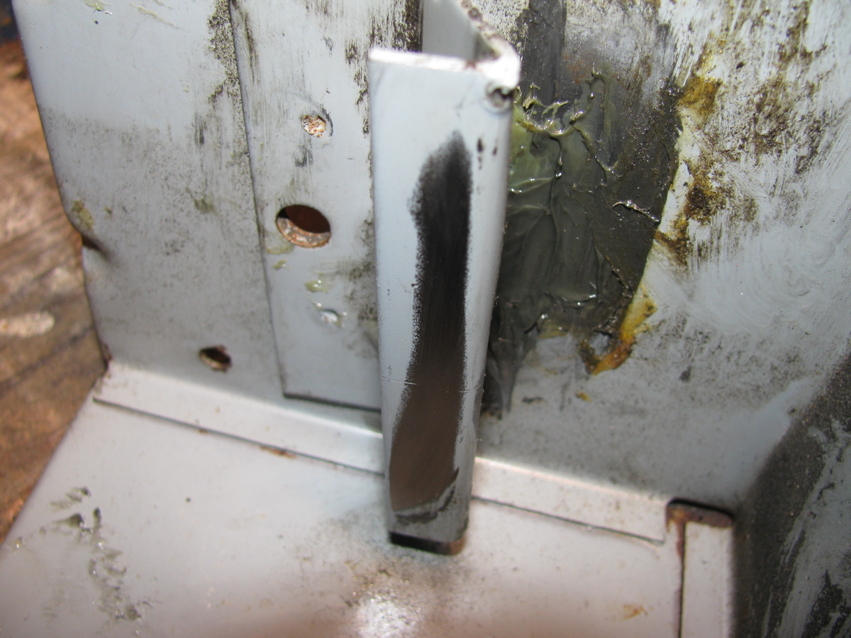
I had to remove a bracket that holds the remnants of the Webasto coolant heater system to get at the short hose, and remove the bell housing vent to get it out of harm’s way (syncro bell housings are sealed to the motor and a vent is provided that leads up somewhere above the gas tank). No surprise I suppose when I broke the plastic elbow when removing the bracket, so it goes.

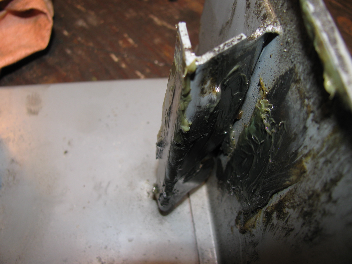
With the bracket out of the way, I could get at the hose. Off it came and time to look at it closely.

Just a pinhole really, but big enough to piss away 1 litre of coolant in about 30 minutes of driving. I had some used hose that I took the chance with, and I got it back in place. I had a closer look at the broken vent elbow, it was plugged solid with some sort of crap.


Then I made a jury rigged repair to the vent elbow using some silicone tubing, stainless tubing, and a bit of stainless wire wrap.

Yeah, I know, this hose leak is a not so gentle reminder that all of the cooling hoses on the van are old and tired. The thing is, I have it in mind to swap in a different motor so I’m being a bit cavalier with this old wasserboxer.
Vanagon – Small Car stainless header failure
Posted by albell in syncro, syncro specific repairs, vanagon, vanagon mods on February 12, 2012
Was installed new about a year ago, in a EJ25 powered syncro. I suppose disappointing would be one way to describe it.


Vanagon – syncro front diff. input seal replacement
Posted by albell in syncro, syncro specific repairs, vanagon on January 13, 2012
Back in October last year, when I had the front diff. out to install a new VC, I noticed that the input seal was leaking. It would have been smart to replace it then, but I couldn’t wait for the seal to be ordered in. Then I procrastinated, put the job off until today. The job is quite straightforward; disconnnect the prop shaft from the front diff., undo the 24 mm nut that holds the drive flange on the input shaft, remove flange, remove seal, replace seal, replace flange, etc.
Addendum: Have a look at this thread on Yahoo Syncro list for discussion on cheaper seal. I didn’t see that thread before I bought the expensive one from dealer.
I’ll be pedantic and list the steps I took:
– chock pass. side wheels and jack and support driver’s side so that left rear wheel is off ground (you could have both wheels that side off the ground, would be easier to rotate propshaft to get at all the propshaft flange bolts)
– loosen the 3 bolts (17 mm) on the rubber mounts on front diff.
– mark the propshaft flange, the front diff. flange, and the front diff so that you can get all the bits back in same orientation.
– remove the 4 nuts and bolts holding propshaft to front diff. flange (13mm, use 2 open end wrenches), and let the propshaft rest on ground, or support with wire.
– rig up some sort of tool to hold the flange as you undo the nut (24 mm), the nut is on there tight (135 ftlb). My elegantly engineered (ha!) flange holding tool required the pass. side propshaft protection rail to be lowered a tad.
– a 2 arm puller to pull the flange off the shaft, came off very easily.
– the exposed seal can be pried out with a strong screwdriver. I was surprised at how secure it was in there. Be careful not to damage the aluminum housing.
– some oil will drip out, have a container in place to catch it
– new seal is lubed then, as the Brits say, offered up to the housing. I used a brake caliper piston to carefully drive the seal home.
– then the flange, and the washer and nut. Again you need to hold the flange as you tighten the nut.
– propshaft back up and secured.
– some gear oil squirted in the fill hole (17 mm socket head plug) just back of the driver’s side inboard cv joint.
– the diff mount bolts left loose for a few miles, then tightened up. Just to allow the front diff to settle in a happy place (a sort of horizontal self alignment).
Addendum: overview of area. 26 = 24 mm nut, 25 = thick washer, 24 = input flange, 23 = seal (22 = circlip and 20 = bearing. Both un-involved with this repair)

Here are some pics:
See the oil splash?

Propshaft removed, the 24 mm nut that holds the input flange on is revealed.

Flange held firm using homemade tool, nut loosened.

Flange off, seal exposed.

Shots of how the brake caliper piston is a good fit to use as seal seating tool.


New seal installed.

Vanagon – syncro viscous coupling anatomy – part 1
Posted by albell in syncro, syncro specific repairs, vanagon on November 21, 2011
This post is just to clarify, a little, how the plates inside a viscous coupling (VC) are arranged. My post on replacing a VC shows more pictures of the assembly and the seals.
Maybe a couple of pics of the VC (end plate removed) to set the scene. Note the end shims, and the absence of the circlip (groove for it in shaft is visible) that keeps the plates all together.

Another angle, end shims removed.

There are 24 pairs of plates in the VC. One set are keyed to drive (or be driven by, semantics) the VC housing itself. So these plates have notches around the edge that fit in internal splines on the VC housing. They also are the plates with the circular holes in them. The other set of plates, slightly smaller in diameter, are keyed to drive the central splined shaft. They have slots in them. The propshaft from the transmission is connected to the housing, the pinion of the front differential is connected to the central shaft of the VC. The silicone fluid filling the VC is what mediates the power transfer between the plates. I won’t be going into the silicone fluid in this post.
There are spacers between pairs of plates, and these spacers fit into the hole in the middle of the plate that is keyed to the housing. The spacer is (all measurements are approximate) 0.065″ thick. The plates themselves are 0.040″ thick. So with the spacer partially lying in the hole of one plate, it only projects about 0.025″. That means the plate pairs are separated from each other by 0.025″. I think it is time for a simple diagram.

Does that diagram make sense to you? You can make out the spaces between the plate pairs in this picture of the entire stack o’ plates out of the housing but still on the shaft.

Oops, looks like I left the last plate in the housing. Also the aluminium ring I am using to support the plates is causing the plates at the end to be pushed upwards. Of course when in the housing they are all aligned. Here is a closer view, no mistaking the pairing of the plates.

And here is a stack of 2 pairs, plus one shaft keyed plate on top.

I think I have established that the plates are in pairs 🙂
I’ll post pictures of the wear patterns on the plates and try and relate that to the pairing of the plates in the next part. All comments and corrections welcome.
Vanagon – syncro viscous coupling replacement
Posted by albell in syncro, syncro specific repairs on October 23, 2011
I pulled the front diff. on the syncro today to replace the old failed (weak) viscous coupling (vc) with a good used one. Dropping the diff. is in the Bentley manual so I won’t describe that part except to say that it takes a bit of wiggling to get it out. I used a motorcycle lift as a transmission jack. Once out I set it on a container to drain.

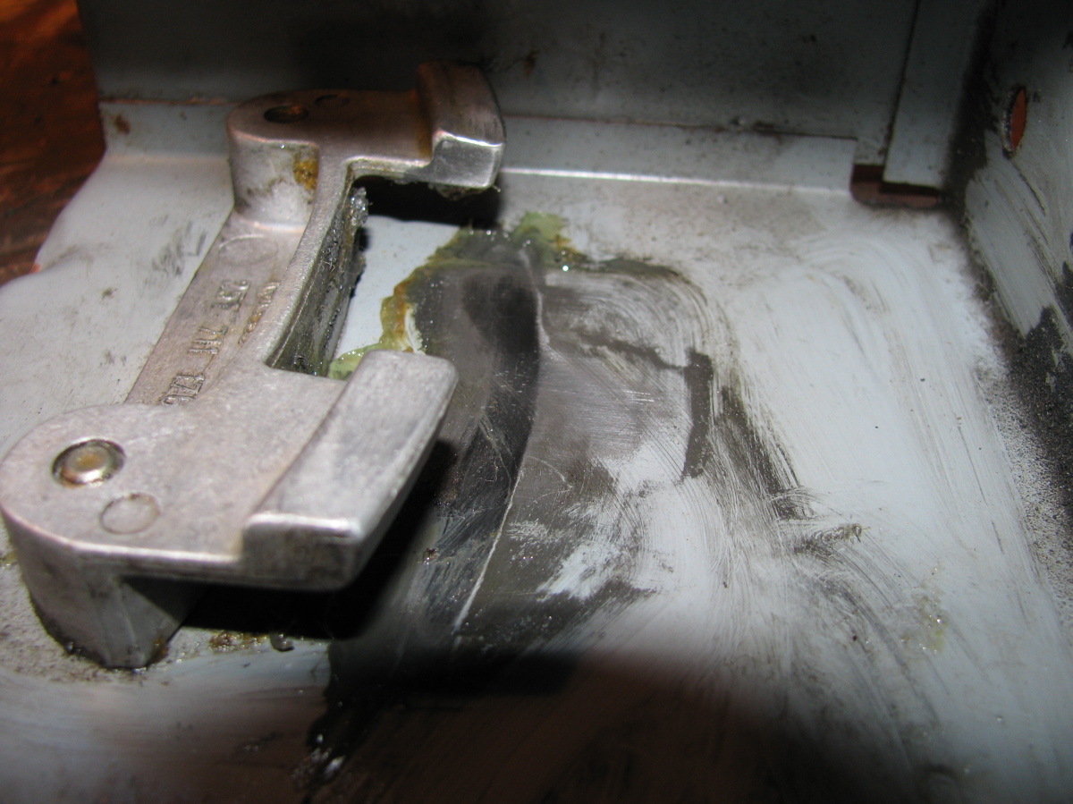
See the dark dirt on the input end? Looks like the oil seal there is leaking, need to attend to that. Once most of the oil drained out I humped it onto the bench, just to look at it.

See the speedo drive sticking out? Then it’s on to the floor and off with the 13mm bolts holding the skinny end on.

Some tapping with soft faced hammer to break the seal and it comes apart.

Yup, that’s the vc sitting there, with a spacer on top.

The vc just lifts right off, exposing the speedo drive gear on the pinion shaft.

Closer view of speedo gear.

With the case separated I drained the remaining oil, applied some sealant to the mating surfaces, put the new vc on the pinion (and didn’t forget the spacer) and the skinny part of the case re-installed and torqued down. All well and good, refill with oil in the morning. Now the interesting bit. I had to take the end plate off the old vc, I was dying to see the inside first hand. The big C-clip came out easily.

That end plate should then pull out, but it wouldn’t come. I thought maybe if I drained the vc and also run an awl around the edge of the plate to remove gunk it might help matters. The silicone flowed out, not as viscous as I have seen in those German videos showing refills, and looking like it might have some gear oil in it. BTW, didn’t smell bad.

Got the end plate off.

Removed the C-clip on the shaft (barely visible in above pic) and pulled the first two plates out to look at the adjacent surfaces. Need any more evidence that the plates do come in contact during hump? Upper plate in pic has been flipped over.

Close ups.


Accepted wisdom is that a weak vc is due to the silicone fluid leaking out. One could expect an O-ring to fail with time, but what I found was something else. I had a look at the X-ring that seals around the central shaft (there are two, one on each end, the one shown is in the end plate). It appears that the X-ring is twisted in the groove, look.

Out it comes, yes, it is twisted.

Another view (damned cat hairs, get everywhere).

This surely must have happened at the factory, a lip of the X-ring getting caught on the shaft during assembly. Tsk, tsk, Steyr-Puch.
Addendum: I’m assuming the vc had leaked some fluid, but even with that folded X-ring I have no proof. The “dirty” fluid from the vc could be gear oil contaminated or it could be metal particles from the plates. Perhaps I can use a magnet to determine?
Vanagon – A viscous coupling
Posted by albell in syncro, syncro specific repairs on October 12, 2011
Thanks to good friend Simon, I have, in my hot little hands, a used viscous coupling. It might be on its way out, getting aggressive after a long hot drive, but it will be great for me this winter.
Here is a view of the front, the front differential end.

A couple of things to note:
-the punch mark up there on the rim between the circlip ends. It aligns with the casting ridge between that screw port and the rim.
– the paint on the screw ports and on the circlip ends.
Closer shot of the punch mark on the rim

The punch marks and the paint on the circlip must have something to do with registration on end cap for balancing. I doubt they were there to help rebuilders, but rather I am guessing the unit was balanced before filling (there are spot welded balancing tabs on the side of the body) and the marks are there to be sure it went back together balanced.
Here is the other end, the one closest to the propshaft.

Coming soon, the install, and perhaps (if I can get my act together) some sort of bench test of the VC.
Vanagon – steering arm boot and radius arm sleeve
Posted by albell in syncro, syncro specific repairs, vanagon on September 19, 2011
It all started so easily, replacing a torn steering arm boot (same boot in all Vanagons).

I figured if I removed the ball joint end of the arm from the steering knuckle I could pull the boot off over it and and not change the arm adjustment (toe in). Out to the ball joint at that end, castellated nut with cotter pin.


I pulled the cotter pin and unscrewed the nut, then screwed the nut back on backwards to protect the threaded end, gave the steering knuckle around the ball joint a couple of good raps with a heavy hammer, then rapped upwards on the nut and the joint popped free. Nice when it happens so easily.

The boot was held on by 2 metal clamps (Oetker?) and I snipped the crimped part with some wire cutters and then pulled the boot out towards the ball joint.


That rubber doughnut on the arm locates the outboard end of the boot. The new (well, used one I had in my parts bin) went over the ball joint and up to the rack. Oh, I did put a bit of grease on the exposed ball joint on the inboard end of the steering rack. I used cable ties to secure the boot the the rack and the rubber doughnut.

Now the interesting part, while under the van I decided to have a look at that side’s radius arm rubber bushing and inner sleeve. These parts do wear out, and the sleeve rusts. I undid the drop link from the sway bar to the radius arm, the 19 mm nut at the out board end of the radius arm (inner bolt not touched, to keep the castor unaffected), and the 3 X 19mm bolts that holds the radius arm to the steering knuckle. As suspected, the sleeve was badly rusted and the bushings shot. The subframe hole also was rusty, but still sound underneath. Pretty well the same set up in 2wd Vanagons, its just that the syncro has that front subframe. Neil has a great write up on fixing his damaged radius rod mount on a 2wd Vanagon.


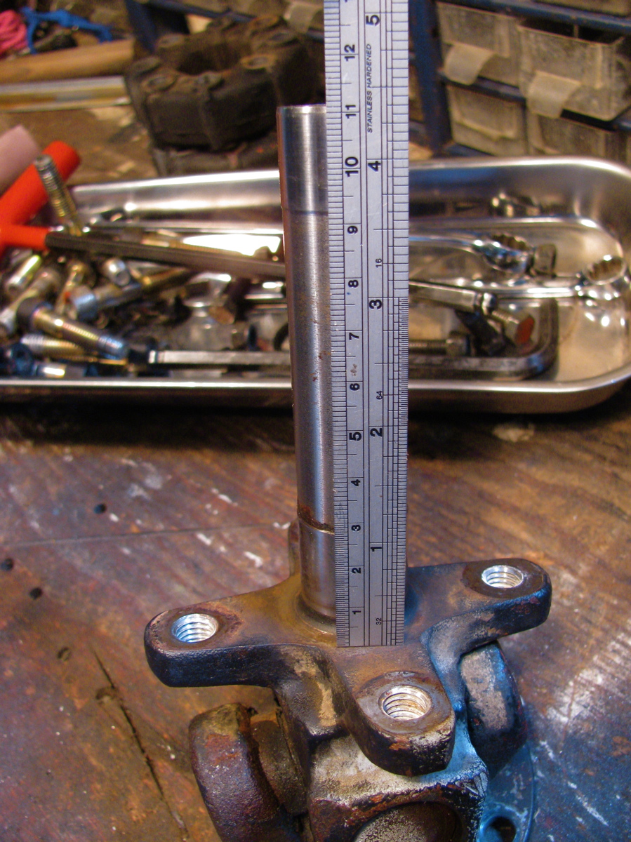
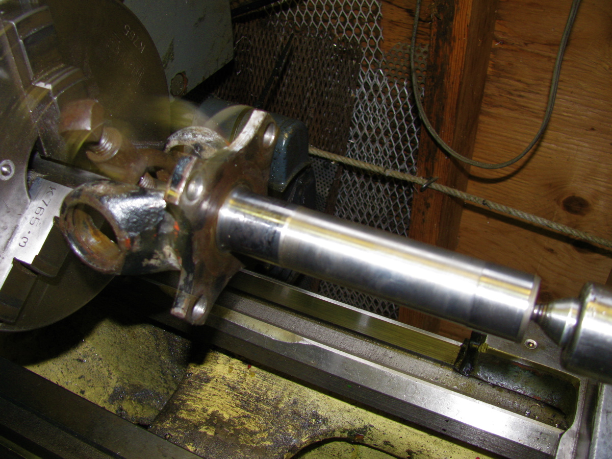
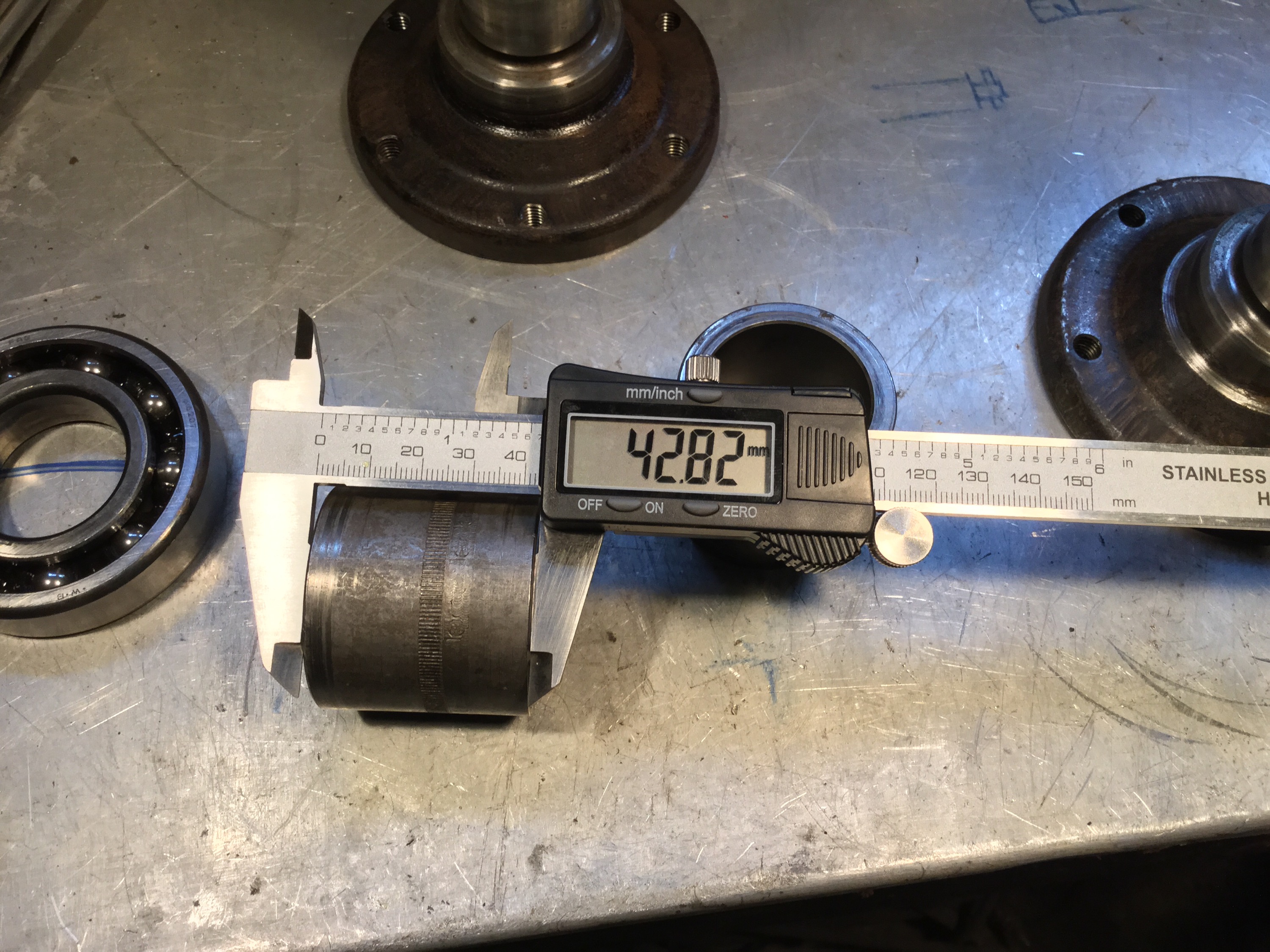
So I have to get new bushings, but right now I decided to make a new sleeve. The dimensions of the sleeve (found on this Samba thread) are: 56 mm long, 25 mm OD, 19mm ID. I did not have any pipe that was close to those dimensions but I had some stainless steel shafting from the scrap yard. It’s not the most efficient way of making a sleeve I admit.

etc…

I could have made a few pot scrubbers with the swarf. The finished sleeve beside the rusty one (btw, the stock sleeve looks like welded tube, and only rusty on the outside).

I slathered everything with a homemade Waxoyl concoction and put it all back together. I’ll order some new bushings.
Vanagon syncro – transmission oil change with complications – Solved!
Posted by albell in syncro, syncro specific repairs on July 1, 2011
A week and four (!) attempts later I finally have the leak fixed. It’s a tale of woe and I guess you could say blindness on my part. When I re-installed the cover plate and noticed the drip at one of the lower cover bolts I assumed the leak was coming from a poor seal at the plate. So I drained the oil and left the cover plate off overnight. Next day I cleaned the mating surfaces well with brake cleaner and used Permatex grey RTV on the sealing surface. Filled the transmission and it still leaked, a small drip at one of the cover plate lower bolts. Now I was peeved. Emails to Daryl at AA Transaxle gave me some confidence, he suggested that I make sure that the cover plate was flat and that the 6 mm socket head bolt under the cover plate was good and tight. So once again I drained the transmission (cover plate off again) overnight. Next day I set about making sure the cover plate sealing surface was flat. I tried flat filing but even with the file loaded with chalk, aluminum filings would ball up and scratch the surface.

So I switched to lapping the cover on a bit of granite using a couple of grades of carborundum grit and WD40 as a lube.
Coarse grit:


Finer grit:


You can see a few larger scratches, must have had some coarse grit carried over. But that doesn’t really matter in this situation, what I wanted was the the cover plate sealing surface to be flat.

Back at the transmission I removed the old silicone sealant which what I thought was squeeze out from the original install of the cover plate, right adjacent to the cover plate hole rear side. This was where I was blind, I should have thought more about why there was so much clear silicone there. I also carefully filed what I thought were slight ridges around the bolt holes on the cover plate sealing surface. Here is an example (you might guess that I was grasping at straws here):

Filed:

As another example of me being gormless, I even smeared some RTV on the area where I removed the old silicone caulk on the case seam. Why did I not put more on and further up the seam? I don’t know.

Cover plate was caulked and put into place.

I was generous with the caulk – well that’s what I have been told 🙂
I let the stuff cure for about 5 hours before I filled the transmission with oil. Can you guess what happened? Yes, still a little drip. Chagrin does not adequately describe my feelings at this point. I went under the van and looked carefully and I noticed oil seeping out from the top edge of the little it of RTV I smeared on the case joint (pictured above). If I put a corner of a rag on that spot the drip at the lower bolt would stop. Why had I not noticed this before. More info from Daryl and a sinking feeling that I might have to pull the transmission and reseal the case joint. But I decided to make one more attempt. Again, an overnight drain of the oil and this time I scrubbed and degreased the case joint all along the side of the cover plate hole. I bought some of the expensive RTV sealant, “The Right Stuff”, it had a few good recommendations and is a fast curing goop.
Picture here of the cleaned area (cover plate sealing surface was later cleaned of the old grey Permatex):

I also gave that socket head bolt another bit of twist. Then I smeared on sealant over the case joint, and on the cover plate sealing surface, not very pretty:

I let the stuff cure for a few hours then refilled the transmission and went into town on errands. I was not optimistic about success, but I’ll be dammed if the damn thing is now sealed tight! One day later and it is still dry. I’ve come to the conclusion that the original silicone caulk that I removed from the case joint area was put on to stop a leak. I bet it was done when the transmission was rebuilt.
I learned a few things from this fiasco. Apart from being more observant I discovered that when putting on the skid bars/plate on the syncro, install the bolts loosely until all are in place, before tightening. That makes it so much easier. I also found that my Snap-On transmission wrench (17 mm hex) was awkward to use on the fill plug (but very good on the drain plug) so I cut a section off my 17 mm allen key and used the short bit on a 17 mm socket, and even better, on my 17 mm ratcheting spanner.


Vanagon syncro – transmission oil change with complications
Posted by albell in syncro, syncro specific repairs on June 24, 2011
A very brief overview of a transmission oil change in my ’86 syncro. I had not changed the oil since I bought this van almost 2 years ago and I noticed a very slight oil leak/seep at the bottom edge of the reverse gear cover plate. I figured it would be worthwhile when I had the chance to drain the oil and look at the cover plate. I bought some regular run of the mill 80/90 wt gear oil with the idea that I would put in the fancy gear oil later after I fixed the cover plate leak. As it turned out, this was a smart move.
The oil fill port is on the right hand side of the van just above the shift linkage rear bushing. The drain port is near the rear near the midline. Important to first see if you can unscrew the fill port before trying the drain port. To get at the fill port easily I found it best to remove the rear skid plate/bars; 2 X 17 mm nuts and bolts at the engine carrier bar, 2 X 17 mm bolts and 2 X 17 mm nuts and bolts at the forward end of bars( actually there is a 15 mm nut on the upper left hand skid bar mount), and to detach the shift linkage rear bushing housing; 2 X 13 mm nuts and bolts.
Kinda silly picture of skid plate out.

Oh, I should mention the tools I used to remove the drain and fill plugs. A 17 mm allen key, and a nice Snap-On tool with 17 mm hex. I needed the allen key to help the Snap-On tool at the fill plug, there was not enough space to fully swing the wrench (you know what I mean).

And more obvious advice: clean out the hex recess in the plugs with dental pick, toothpick, compressed air, whatever. Ya gotta have the wrench make a good fit. I squirted penetrant/rust buster on the plugs, more out of habit than expecting that the damn stuff actually does anything. Next pictures shows the fill plug (shift linkage still up in place) and the wrench in in the plug, riveting story eh?


Thankfully the fill port plug unscrewed with no problem. Next, on to the drain plug. The wet spot is the penetrant fluid stain.

It too came out with no trouble. The magnetic plug had a bit of fuzz on it, but I think this is a pretty normal coif.

While the transmission drained, I removed the weeping cover plate. It seemed to be leaking at the bottom edge.

Plate off, evidence of silicone caulk as a sealant.

Close up of the bottom corner that I suspected the leak was coming from. No smoking gun that I can see, minor scratches, almost a crack like line there though, no?

At this point I was advised by my son that I need to drive him to some sort of “date”, grrr. I should have let the transmission drain overnight and degrease the mating surface of the cover plate before applying rtv silicone and re-assembling (as per Daryl of AA transmission’s advice). So I slapped on the the silicone and the plate, and set about filling the transmission. I made a fill hose with some pvc tubing and a funnel.

All filled and the skid plate back on, the shift linkage re-installed, and the damn cover plate leaks more than before. So, tomorrow I’ll do it all over, this time properly letting the cover plate area drain and be de-greased. Daryl also advised flat filling the cover plate flange to make sure it is flat.
Vanagon syncro – NOS shifter box
Posted by albell in syncro, syncro specific repairs on May 30, 2011
Courtesy of Bill M.

Vanagon syncro gear shift lever maintenance
Posted by albell in syncro, syncro specific repairs on May 29, 2011
R. Jones pushed me into this, he wanted to see how it all goes together. I’ll go through it on point form, pictures and text. Bentley has an exploded view and instructions for back up.
On the way out to the workshop I noticed a cool spider on a leaf of one of the jade plants we put outside for the summer. Got a quick snap before it moved. If you want good pics, head to A. Gordon’s Wordlessme.

Back to the job, first unscrew gear lever knob and pull off the rubber shifter boot. Then mark the position of the upper plate on the lower plate. I scratched circles through the two holes in the upper plate.


 No need to remove the two 10 mm nuts you see there right now, we will be taking the two plates out together. Then it’s under the van to drop the spare and remove the shifter box, four 10 mm nuts and washers, careful, they drop easily 🙂

Box removed

Now remove the vertical from the horizontal between the “ears”. It’s a 10 mm stover nut and a washer on one side, and a 13 mm headed bolt on the other.

Now you can get back into the van and pull up the plates and shifter, and take it to the bench for disassembly.

There is a set screw on that metal collar on top of that spring, hold it tight as you back the screw off and remove collar and spring. The shift lever will slide out of the housing assembly. Look at the “T” end of the lever, remove the 2 plastic bushings. These are wear items and it would be a good idea to replace them.


I didn’t as I did not have any on hand, and I couldn’t be arsed to make some up. The bolt that rides in there looked a bit worn and I suppose the small amount of play in there does contribute to the overall feel of the shifter. Here is the bolt back in the bushings.

And the wear.

Back to the other parts, now you can remove the two stover nuts holding the upper and lower plates together, you did mark position of the two plates first right? The white plastic collar on the underside of the upper plate is pried out.

Then the entire inner workings, rubber collar and all, can be pushed out from top to bottom. It might be tight, but palm pressure is enough to do it. Careful not to break the upper plastic.

The two white plastic bearing shells can be pried out of the rubber and that will allow an internal spring to sproing things apart.


Now clean all the parts.

Reassembly is pretty straightforward, first squeeze the split shells into the rubber collar, might be a bit of a struggle.

Then the one inner bearing with the protrusion is pushed in from below until it snaps into place. Good time to put a little grease on the rubbing surfaces. Not too much, Bentley makes no mention of lubricating the plastic assembly and I have seen some that are caked in grease and dirt, so it is probably best to go light with the schmalz. Do, however, put a dab of grease on the gear lever where it goes into the plastic assembly and in the bushings on the “T’ at the end of the lever. Note that the rubber collar has a “top”, the little ridge, see? Sorry about bad focus in the next couple of pics.
 Then put the larger of the two springs on.

And press the upper bearing into place, again it snaps in. The rubber collar allows the split shells to spread.

This assembly is now pushed into the upper plate.
 Followed by that plastic collar.
 Put the upper and lower plates together and secure (in the right place using your marks) with the two 10 mm stover nuts. I risked Zinc and or Cadmium poisoning and buffed up the shift lever. The lever is inserted into the bearing assembly, the spring put on, and the collar locked down in place (there is a dimple on the shaft).

Out to the van, and pop the gubbins in.
 Then under the van to connect the shift lever to the ears using that bolt and bushing arrangement. Bolt the box back on and put the spare tire and tray back in place. Back upstairs and rubber boot and shift knob back on.
 That’s it. Oh, I suppose I should have mentioned that you can get replacement plastic parts for the assembly from the usual suspects, Van Cafe, Go Westy, Bus Depot etc. I re-used the old parts, they seemed to be in OK shape.
Vanagon syncro front shifter box pics
Posted by albell in syncro, syncro specific repairs on May 28, 2011
For Doug M., wanted to see the wear patterns. Looks in good shape for being almost 25 years old and god knows how many shifts.
Vanagon syncro shift linkage – rear, and a glance at the front
Posted by albell in syncro, syncro specific repairs on May 22, 2011
I’ve been noticing that I sometimes have a little difficulty shifting into 1st and 2nd. Spraying grease on the exposed wear points on linkage under the van makes the difficult shifting go away for a while, so even I got the message that it needed some attention This diagram shows the linkage, my van has neither the shift linkage protective tube, nor the rubber boots protecting the rear bushing.

Another difference is that as well as the roll pin that secures the horizontal linkage to the vertical link right at the transmission, my van also has a horizontal bolt and nut securing the two. The linkage at the rear comes off pretty easily, except that the skid rails on the syncro does restrict access to some nuts and bolts. The roll pin is tapped out with hammer and small drift from the inside of the vertical link, that link drops from the ball link which is attached (13 mm nut) to the shaft coming out of the transmission. On the bench, the manky, dirty bunch.


Then all cleaned up.

The brown ovoid shaped bushing was packed inside with a mixture of old grease and grit, took a few minutes to get that clean. The roll pin is worn, I think I should get a new one ( have a spare bit of linkage so I can get the right size at the shop).

Then it’s grease them up and put it all back into the van, with a spritz of Fluid Film. Not really happy about the rubber boot that covers the transmission selector shaft. It does grab onto a ridge on transmission, but outboard end of it doesn’t seem to attach to anything. You can see a glint of exposed shaft in the pic below.


Shot of the linkage U-joint, which seems/feels pretty good, and the forward bushing which takes a bit more effort to get to.


No road test done to see if the shifting has improved, but parked, it goes into all gears nicely.
While I was in the mood, I had a look at the linkage/joint right under the gear shift lever. You know, hidden by that box above the spare tire. I had been reading this thread on the Samba and was curious.

The plastic ears are in place, and not too badly worn. Trust me, you can’t really see because to the grease.

Cleaned off the old grease and put new stuff on.
Vanagon syncro left hand side transmission mount and breather line
Posted by albell in syncro, syncro specific repairs on May 12, 2011
Still buggering around wondering how to raise the front of the transmission to reduce the output flange downward angle. I supported the front of the transmission and pulled the left hand side mount off. The mount on the other side is much less accessible, coolant lines restrict access. I guess I have to say that this is pretty dull blog stuff. Maybe it helps other folks doing the same thing, but mainly I am treating it as a journal, recording what I have done and reminding me what to do if I have to do it again.
So the rubber mount there is attached to a bracket which is bolted to a beam under the van, and to an ear on the transmission.

It is hard to get a wrench up to the nut on the top of the rubber mounts, but an angle head ratchet wrench (17 mm) can be squeezed in there, and the other end attacked with a socket. I found that loosening the three 13 mm bolts that hold the bracket to the beam allows the ratchet wrench to get up there easier. One funny thing, the EKTA-like diagram above show those bolts coming in from above, they don’t. So the rubber mounts and bracket were pulled out. Here is the bracket on the bench.


I sprayed some white paint on the rubber mount bolt and transmission ear just in case the transmission shifted aand I had to get things back in the right spot. As it turned out, the other mount held things in place.
I compared the rubber mounts, upper and lower (above and below the bracket). The upper one is marked with “U”.

Looks a bit collapsed, saw the same thing with the front diff. mount. The bracket was a bit rusty so I scraped off the rust and slapped some POR on it. While the paint was drying, I had a look at the part of the transmission that was exposed with the mount removed. I found the transmission breather hole which, in the syncro, has a plastic tube leading somewhere higher so that the vent won’t take in water if wading in the van. Sometime in the van’s history the transmission was rebuilt and the breather tube was reconnected to the hose barb on the transmission via a short length of rubber hose. It came off too easily so I used some clear PVC tubing to connect it (heating the stock tubing with heat gun and trying to get it on the hose barb was not a success).


It really is a tighter fit than it looks in the picture, I’m confident it will stay in place. I reassembled the mount, with the lower rubber now on top, and had a few minutes of “quality time” re-installing. I did not succeed in finding any new ideas on adjusting the transmission angle, but I am glad I got the breath line better secured.
PS I also re-installed the “new” propshaft I was babbling on about a few posts back, I had replaced one of the U-joints since. Well, the upshot of all of this was that the driveline vibrations are pretty well gone. Still a very, very slight vibe at 50 kph, but it is really acceptable.
Vanagon syncro propshaft comparison
Posted by albell in syncro, syncro specific repairs on May 9, 2011
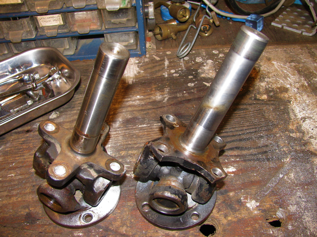
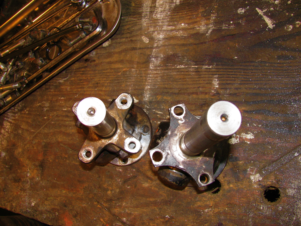
Took apart 2 stock propshafts. The rusty red one is an ’86 model, the black one is from a later van (I don’t know the year). You can see that there are a few minor differences. One important one is the machined end that houses the internal bushings. Note the thickness of the internal bushings, the newer shaft has much thinner bushings. Both units have shafts that are the same diameter so it’s the bushing housing that is a smaller diameter in the newer shaft. Also the shaft lengths differ, the older one being longer. The newer shaft has the o-ring in a groove, the older one has a rebate to hold ring.
Some more trivia:
1. the black (newer shaft) had one U-joint that looked stock and one that had a blanked off grease nipple. I am assuming orig. U-joint was replaced
2. The rusty red one, from my van and I am confident that is stock, does match the diagram I posted in previous blog entry. The black one does not match in some details.
3. both internal shafts are same diameter
4. overall length of shafts differ by a couple of millimeters. The black, (newer), shaft being shorter.
5. all the socket cap screws are the same
6. I haven’t found, and this does not mean none exist, any vw part number on both shafts
7. giubos are identical
8. the part of the joint that mates to the trans/front diff, on both shafts are as identical as machined sand cast parts can be
9. the diameter of the propshaft proper is pretty well identical on both shafts (3.155″)
10. both shafts assembled with U-joints out of IN phase


Giubo end of Vanagon syncro propshaft
Posted by albell in syncro, syncro specific repairs on May 8, 2011
I played around with a spare propshaft that I got the other day (thanks again SImon). I installed it in the van as is and it did have a vibration at around 50 kph. Wasn’t a huge vibration, but it wasn’t acceptable. Believe it or not, but it felt like the vibration was to the rear rather than the front. I took the shaft out and set about taking the giubo end apart. First thing noticeable was the U-joint had slight axial play in one of the crosses. I took off the circlips at that joint and they measure approx 0.050 in thickness. I installed a pair of 0.060 circlips and that eliminated the play. The ears of the joint look a little beaten. Also, doesn’t look like the circlip is fully in the groove does it? But it is… I think 🙂

I still could detect play at that end and guessed it might be from wear in the internal shaft and bushings. So the giubo and end u-joint had to come off.
First, here is a pic of the end of the shaft.

If you look closely you can see the head of a bolt in the inside face of the U-joint. This is to plug a grease nipple port and indicates the joint is not stock. Close up of that area.

Before taking things apart, I sprayed some paint on the works so I could put it all back together in the same orientation.

Then off with the bolts that hold the giubo to the propshaft. The giubo and joint pull out. The shaft doesn’t look too bad on the end.

Then remove the bots holding the giubo to the joint.

That end doesn’t look too bad either. You can see the shaft is thicker in the two spots, that’s where it rides on the internal bronze bushings in the prop shaft. Have a look in the hole in the propshaft. There’s an o-ring in a groove at the end. My other propshaft had the o-ring in a rebate, not a groove.

Now the giubo, sitting roughly in place, and it had washers on either side. Pretty cruddy washers, and my other propshaft did not have them.

With the giubo removed from the joint, I reinserted the shaft into the hole and tried it out for size. It felt pretty good, no slop. So where did that looseness come from that I felt when it was all assembled?
I decided to lube it all up and put it back together. I used a band clamp to squeeze the giubo into shape to let me get the bolts back in to attach joint to rubber.

And same technique when attaching assembly to propshaft.

Well, all assembled (minus those washers) and it feels nice and tight. No play like before. So I put it back into the van and had a test drive. It still has some vibration (again around 50 kph) but it is less. I had to say that didn’t I? Honestly it is better but not what I want. So the shaft is coming off again and I’ll take it to the driveline shop for spin balancing.
Addendum: In the comments Rob advised replacing that U-joint. I agree and I should have mentioned this in the post. I’ll ask the driveline guy to do it this time.
More addendum: Diagram of the end of shaft. Does it look to you like of some sort of cap at the end of the internal tube or is it integral to the inner bushing? I’m thinking the former is the case. Also note that it is a nut and bolt that holds the giubo to the U-joint yoke. In the propshaft above its a bolt, with the propshaft yoke having threaded holes. My other propshaft has same attachment method shown in diagram. No washers between giubo and shaft shown on diagram either. I bet there were some minor changes made to the shaft during production.

Vanagon rear wheel bearing replacement
Posted by albell in syncro, syncro specific repairs, vanagon on April 16, 2011
I noticed some play in right rear wheel (jacking up van and trying to move wheel, 12 and 6 o’clock positions) and a whiny noise when driving which changed in loudness on turns. I figured it was time to replace the bearings. These bearings seem to last a long time but there is a limit I guess. For another good description of this procedure have a look at the English translation of the German IG16 wiki entry. To start here are a couple of exploded diagrams showing all the parts. 
 It makes a lot of sense to take out the axle at same time so that you can re-lube the CV joints and also press the stub axle into the bearing housing on the bench. But I didn’t do that as I was short on time. If you do want to take out the axle, undo the transmission side CV joint when you still have the wheel on the van, unless you are using air tools, so that you can brace the wheel when undoing the CV bolts. First thing is to undo the 46 mm castle nut on the wheel. It’s on there tight (275 – 350 ft/lbs) so you need to do it with the van on the ground and the wheels chocked. Normally I use a 3/4″ drive socket and a long armed drive with some steel pipe as an extension. But this time I tried out one of those “slug wrenches”, I was given one a few months ago. The idea is that (after removing split pin on nut) you attach slug wrench to nut, use a 1/2″ socket wrench drive to apply some force, and at same time whack the slug wrench with a short sledge hammer. Its a bit awkward, the wrench lies close to the wheel so ou have to aim carefully so as to not hit the rim. But it worked, the nut came loose.
  Once the nut is loose, you then loosen wheel nuts, jack up and support van securely, and remove wheel. Then remove nut and the brake drum should come right off easily. Perhaps you might need to back off brake adjuster if the brake shoes hang up on a lip if your drums are old and worn.
 Next step is to undo brake line from the brake cylinder and cap it with a bleeder nipple rubber cap. Then remove the 13 mm bolt that holds the brake cylinder to the bearing housing. Then remove the 2 bolts (15 mm?) from the brake shoe holder at the bottom. I then removed the clip that holds the parking brake line to the underside of the trailing arm so that I could keep the parking brake line attached to the brake mechanism. The brake assembly and backing plate *should* pull off the bearing housing. However, it is located on the housing by one dowel pin on the brake shoe holder at the bottom. The dowel was stuck in there tight and I had to tap it out with a small brass drift and hammer. Don’t use a steel drift to do this, it will mushroom the dowel.
 See the dowel pin below the bolt holes in above pic? Wet area on trailing arm is due to some rust busting liquid I squirted on exposed threads on the 4 bolts holding the bearing housing on to the trailing arm. With the parking brake line detached from trailing arm it is possible to to pull off brake assembly from stub axle and lay to the side on the ground.
  Now remove the 4 bolts (17 mm?) that holds the bearing housing onto the trailing arm, and then the housing should pull right off the stub axle.
  Pretty ugly in there eh? Caked on dirt and some rust. I took the bearing housing to the bench for disassembly.
 The grease seals were stuck in tight, I had to put the housing in the vice and use a longish pry bar to pop them out.
  Above pic shows outboard grease seal removed and the inner race of the outboard bearing removed (it just falls out). On the inboard side, after the grease seal is removed there is a circlip to take care of.
  After circlip is removed the inner bearing can be removed by driving it out with a brass drift from the outboard side. The spaced sleeve in there between the bearings can be shoved to the side so that you can get the drift onto the bearing race. It took a bit of “drifting” to get the bearing out. If you have a press then you know how to do it better. Once that inboard bearing is out, the spacer is removed and then the outboard bearing outer race can be driven out. In my case that bearing was really stuck in tight. I used an old disk brake caliper piston to drive the bearing out, was a lucky good fit.

 There is a spacer in that gob of grease.
  Cleaned up the housing a bit, especially the bearing seats.
 All the parts arranged.
  Inboard bearing greased and carefully tapped in using that plastic headed dead blow mallet. Picture shows bearing started in housing, not fully seated.
  Bearings were tapped in carefully (a press would be better), the circlip inserted in the inboard side, the spacer installed and the grease applied liberally around the spacer, and the grease seals carefully installed. Again, picture shows bearing started, not fully seated.
  Now at this point, with the housing reassembled, if I had taken the stub axle off the van it would be pressed (or carefully tapped) into the bearings. But what I did was take the housing out to the van, slip it onto the stub axle making sure I didn’t damage the grease seals and that the spacer lined up on the shaft, and I pushed the housing onto the stub as far as I could. I bolted the housing to the trailing arm, then I used the brake drum and the big nut to slowly draw the stub axle into place. This method worked well. Oh, before I put the housing back onto the trailing arm I cleaned out the dirt and loose rust from inside the arm and shot a whack of Fluid Film in there.
  Then its a matter of putting the brake assembly back on, re-attaching the brake line (was a pain, I had to loosen the slave cylinder on the backing plate to get the thread started on the union), then the brake drum, big nut snugged up but not torqued, the wheel, and then get the van off the jack stands. Torque the big nut to spec (see diagram at beginning of post for torque specs), split pin installed, lug nuts torqued, and its done. No play in bearing when the wheel was grabbed, and the whine when driving was gone. I’m guessing that most Vanagon owners will only have to do this job once, or maybe twice, in the van’s life.
Addendum, April 30 2015, some measurements for Josh 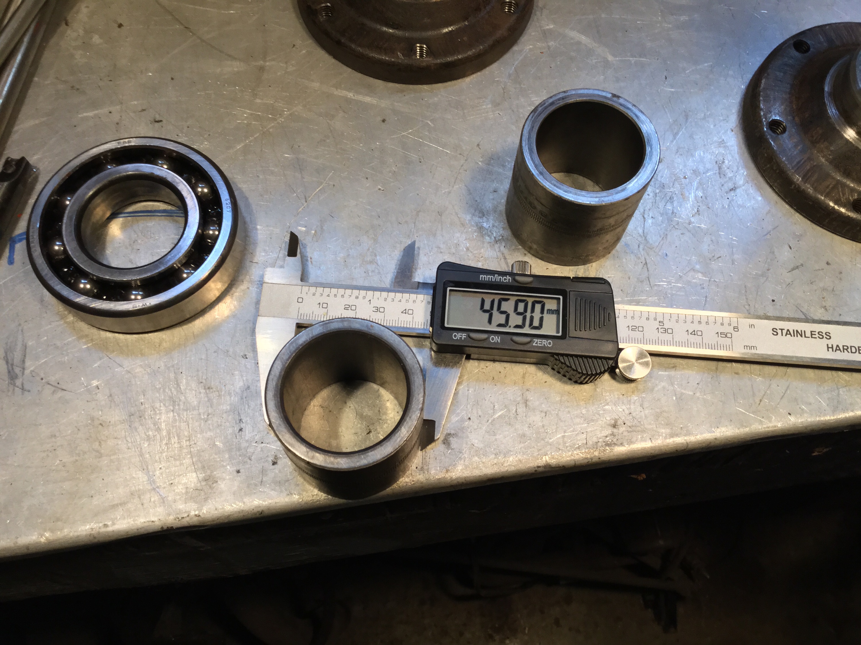


Vanagon ignition switch
Posted by albell in syncro specific repairs, vanagon, vanagon mods on February 24, 2011
It has been “discovered” that the Vanagon ignition switch is a weak design. Why? Well it switches a fair bit of current and the contacts seem just adequate for the job. All right, I admit I have no real data to present to prove this, but maybe it is wise to have OCD and switch off accessories (heater fan, wipers, lights) before starting the van. If these loads are present then contacts in the switch have to handle a bigger current, and the resulting sparking will degrade the contacts over time. Mind you, the actual switch is relatively cheap ($20 – $40), so this really does fall under the category of Vanagon nerdom.
Excerpt from manual showing switch:

David B.’s photograph of dissected used switch:

I must be so bored to resort to posting such a flimsy entry 🙂
Update: Maybe its not such a flimsy entry after all, Jay Brown sells a relay package to reduce switch load.
Also, headlight relays on there own will reduce load on the ign. switch.
Vanagon syncro propshaft balanced – verdict
Posted by albell in syncro, syncro specific repairs on February 16, 2011
As I mentioned a couple of days ago, I had my prop shaft balanced and I finally have it installed. I drove about 10 km with the front diff. mounts loose to allow it to “settle in”. Today I tightened them down and I can report that the propshaft is pretty smooth. Of course your kind of hyper vigilant in this sort of situation, and I can feel a very very slight vibe at around 60-70 kph, a little like having deep lugged tires. I’m happy with the result.
Syncro propshaft balanced
Posted by albell in syncro, syncro specific repairs, vanagon on February 14, 2011
I finally had my propshaft professionally balanced by local driveline rebuilder/balancer. The tech took off the factory weights, welded on new ones (washers) and also took out a slight “hump” in the shaft. It was balanced to within 0.001″ run out at each end. I repainted the bare spots and I’ll install it today if the rain stops.

Brake flex line – inside the old one
Posted by albell in syncro specific repairs, vanagon on February 9, 2011
I was advised that it was a good idea to replace the brake flex lines while at the same time I was replacing the calipers as the lines degrade over time. I don’t doubt that they do degrade, but my old line looks pretty good.

Reverse light switch replacement
Posted by albell in syncro specific repairs, vanagon on February 9, 2011
Back up lights wouldn’t come on, checked to see if I had power at the switch, yup, jumping the wires lit up the back up lights, so switch must be broken. The switch on the syncro is on the left hand side of the transmission, right beside a protrusion. Its an easy repair, 19 mm wrench, less than 5 min.


The old switch, the round end moves in and out:

New caliper for otherside
Posted by albell in syncro specific repairs, vanagon on February 9, 2011
Replaced the front right caliper too, and that side brake flex line. I ran out of daylight to replace the left side flex line, I’ll do it soon. Notice the anti-chafe areas seem to be not positioned right… they could not be moved on the line, but one at least is rubbing against the suspension upright and doing its job.


Replacing that buggered caliper
Posted by albell in syncro specific repairs, vanagon on February 5, 2011
I bought a rebuilt caliper to replace the one I buggered up the other day. Its a pretty straightforward install. The new caliper came with a bolt for a banjo type fitting for the brake line, but no worries, the flare connection fits properly in the threaded hole. There was one minor hang up, the new caliper slider hit the brake backing plate, see the front (left) part of the slider hitting the backing plate?

Another view:

So I cut of a bit of the backing plate:

And then it all went together fine and I pressure bled the brake:

Had a look at the other side, here is a shot of the broken nipple (soaking in a rust buster type fluid):

I wanted to bleed this side via the hydraulic line connection, but I couldn’t shift that union so I thought it wise (!) to soak the joint in rust buster and get back to it later. I got enough brake pedal with the rest of the system bled. Here is a shot of that same side and see how that caliper slider clears the backing plate:

Last thing was to bleed the clutch hydraulics. No air came out ( surprisingly I had clutch function before bleeding), but a fair bit of dirty fluid:

Vanagon dash removal, pedal assembly repair, and heater core flush
Posted by albell in syncro, syncro specific repairs, vanagon on February 1, 2011
I’m just about finished with this project. I decided to pull the dash and have a look at both the heater core (I didn’t have as much front heat as I thought I should have) and to fix a squeaky clutch pedal. Removing the dash has been covered elsewhere, a good reference is on Ben’s Place website. Once the dash is out, the heater box can be removed (clamp off coolant lines). One tool that makes this possible is a phillips bit socket on a long extension. Some of the screws holding the heater box to the van can be rusted in tight, so take care. The heater box is then split along the seam, there are spring clips to remove first (and welded plastic tabs if box has not been split before). Then the heater core comes out and I cleaned it inside an out with a hydrofluoric acid based aluminium cleaner. I diluted the cleaner, it was a pretty strong stock solution. Flushing with the cleaner produced a lot of black sediment, I’m hoping that getting rid of that stuff will improve the heater’s performance.
Dash off and heater box out:

Core before cleaning:

The other side:

And a shot of one side after cleaning and installed in box:

Also took the opportunity to squirt some oil on one end of the heater fan. It did feel easier to spin after even this casual oiling:

With the dash off its relatively easy to pull the pedal assembly out (after draining brake fluid etc). I have a spare assembly that I rebuilt and talked about in this post, but I decided rather than swap over the units I would rebuild this one. As in the other one, this assembly had a worn hole in clutch pedal and worn clevis pin.

But also, the clutch rod was bent. Wonder how that happened? Maybe previous owner had replaced clutch master cylinder and didn’t insert pin correctly and the first time pedal was depressed it bent the rod before it popped into place?

I took the chance and straightened it out, then I enlarged the hole in the clutch pedal and clevis to make it round rather than oval, and turned a new, oversized, (and roughly finished) pin.

Cleaned everything up, greased, and reassembled.

The pedal feels a whole lot better. Now the chore of putting it all back into the van. Nothing special to report here except to note that it is easier to reattach the clutch line to the clutch master cylinder if the mc is disconnected from the pedal bracket. Oh, and a heat gun is needed to soften the plastic vacuum line to the brake booster to get it off, and to put it back on. The dash is back in place and tomorrow I’ll be reconnecting the electrics and flushing the hydraulics.
Replacing transmission driveshaft seals
Posted by albell in syncro specific repairs, vanagon on August 19, 2010
Jim writes:
Tools: nothing special in a modestly-equipped shop. Assumes you have a small cheap inertial puller set.
Do one side and then the other. In both cases:
1. Jack up the first side, chock the other. release the emergency brake and then put in neutral. You’ll need to lock up either the wheel and other times turn it (to remove and tighten the CV joint bolts) or the flange itself (for circlip removal/refitting) at various stages of this procedure.
2. remove the allen-head bolts holding the inner CV joint to the transmission flange. Clean out first with a small pick, then tap in allen wrench with a small hammer to ensure seating in the fastener. Otherwise, you risk rounding out a bolt.
3. Drop and bag the CV joint for cleanliness. Have some good moly greasy on hand if it needs repacking.
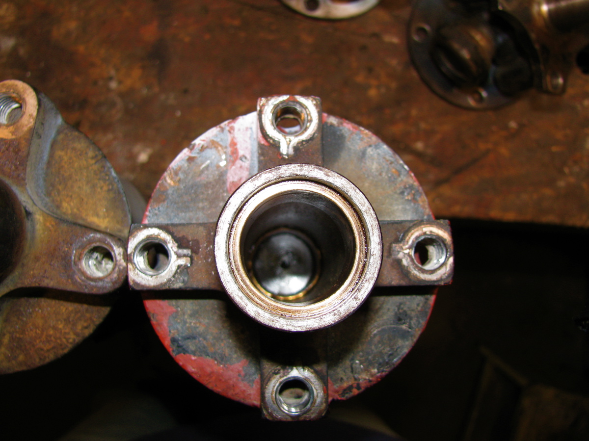
4. You’re looking at the flange. Talk a hammer and a sharp tool and drive it into the plastic plug in the center of the flange and pry out.
5. Remove the C-clip with two screwdrivers, better a screwdriver and a hook tool like a spark plug boot remover.
6. Use a 3-jaw puller to remove the flange.
7. Remove the two phillips screws that hold the plastic dirt shield to the transmission.
8. Clean everything you removed by soaking in gasoline, be sure you get the spring washer from inside the flange. Now you can see the seal in it’s aluminum housing.
9. Use a sharp-pointed tool east and west positions on the seal itself and punch holes.
10. Use the screw tool with the puller to screw into the holes you punched in the seal. There’s a big old ball bearing behind the seal, don’t worry about it. Keep turning the puller screw into the seal housing until the pressure of the screw point against the bearing rides the seal out of its home. When you tighten the puller screw with a wrench, you’re stopping the screw point against the bearing and riding the seal up the threads and out of its seat.
11. Oil up a new seal with transmission grease and tap home with a stick, dowel or rod about 1/2 inch diameter and about 8 inches long.
12. Tap flush with seal housing, keeping tapping constant while moving rod or dowel constantly around seal housing.
13. Remove soaking parts from gasoline and clean.
14. Refit plastic dust cover and screws and then refit flange. Protect with section of 2 x 4 and wail away with hammer until seated.
15. Refit spring washer cup out (center part the closest to you).
16. Refit clip ring with two medium flat screwdrivers. The first time you do this, it will take about ten minutes. The second time, about 30 seconds. There is a technique.
17. After fitting clip on axle stub, tap clip into place with small flat punch and hammer to make sure it is seated in the groove against the pressure of the spring washer.
18. Tap in new seal, smear joint with RTV adhesive.
19. Refit CV joint, packing with grease if necessary.
20. Repeat from step 1 for next side.
21. Drop shift rod by removing upper and lower 13mm bolts and nuts.
22. Remove transmission filler plug with 17mm internal socket.
23. Fill transmission per Bentley.
24. Replace filler plug.
25. Lube shift cup and shift bushing with moly grease, replace bad rubber as necessary.
26. Rehang rear shift assembly as reverse of removal in step 21.
27. It’s over
Viscous coupling rebuild
Posted by albell in syncro, syncro specific repairs, vanagon on August 16, 2010
In German, on this site http://www.2wd-goes-syncro.de/. Videos showing a VC being taken apart, cleaned, and new fluid added. Well worth a look.
Syncro fuel filter replacement, Part 2
Posted by albell in syncro, syncro specific repairs on August 4, 2010
Got the new filter today, and after working on my wave maker project I set about putting it in.

Installed into bracket.

Tucked behind spring tower, fuel line outlet attached first.

Then filter pulled forward towards front of van and inlet line attached. The the bracket moved into place and attached to tower with the screws. Do the rear screw first, then the front screw. Rear is towards rear of van, front is towards front of van.


Next is reinstalling carbon filter/canister bracket.

And finally the canister itself. I think I installed it higher on the bracket than before, but I don’t think I have crimped any of the lines at the top of the canister.

Overview shot of area.

In hindsight, I guess its not that bad of a job. But I can imagine it being hell with a van that has seen more salty winters. While I was in there, I removed an A/C line and the A/C drier that sat behind the charcoal canister, I’m stripping all the A/C stuff from the van.
Syncro fuel filter replacement, Part I
Posted by albell in syncro, syncro specific repairs on August 3, 2010
The design team responsible for the fuel supply system in the Vanagon Syncro was led by a descendant of Leopold von Sacher-Masoch. No? Well how do you explain the location of the fuel filter then?
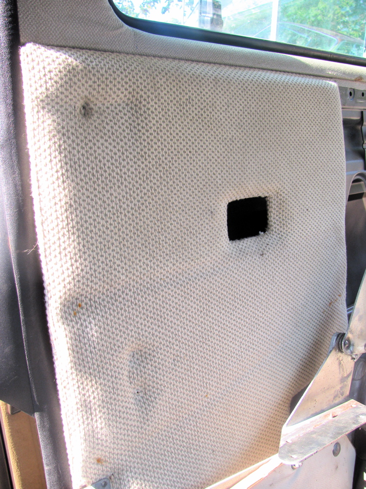
In camperizing the syncro I came upon the problem of screwing down the folding bed/rear bench brackets to the rear deck. I mentioned in a previous post how I drilled and tapped holes, but the rear deck is not thick enough to get more than one complete thread in it, so I went about making some little backing plates to build it up. On the passenger side it is no problem, the area is in the wheel well. But on the drivers side you have to reach up in wheel well, past the carbon filter and behind/above the gas tank. While doing that I decided to change the fuel filter which is located in that region.
Actually the fuel filter is attached to the inboard side of the spring tower. But you wouldn’t know it from this diagram (its #25, oh and the charcoal filter which is part of the emission control system is not shown here).

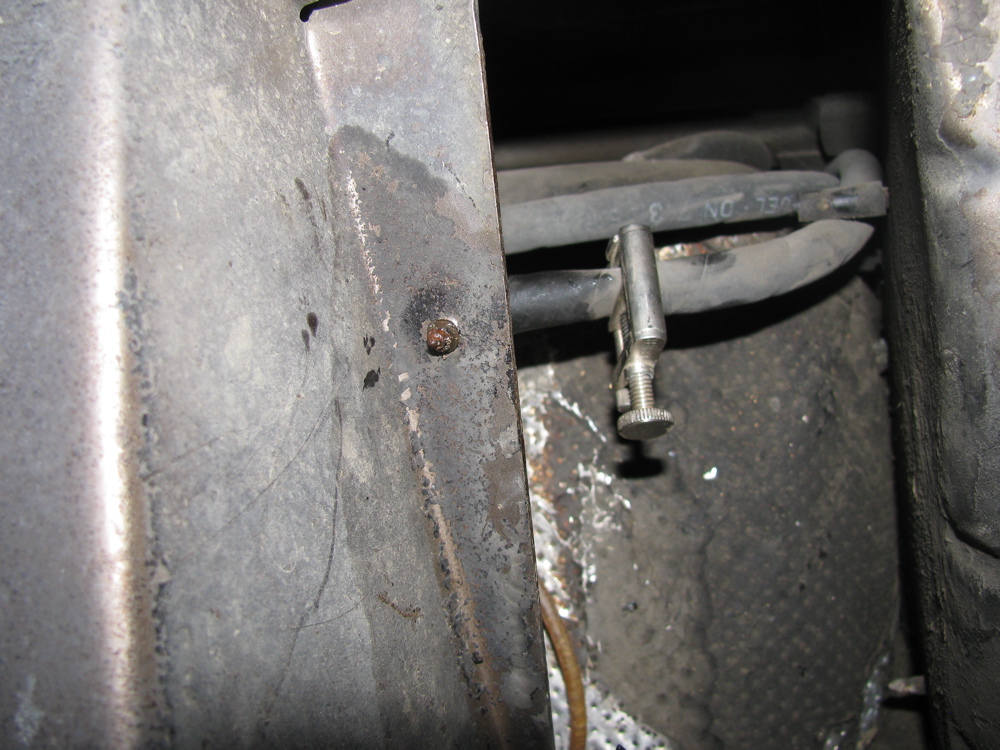
I did not take an “establishing shot” type pic, but here is a close up of the front side of the spring tower and the charcoal canister (I had removed the gear clamp that holds the canister to its bracket, which in turn is screwed to spring tower).

With the canister moved out the way a bit, you can see the filter, inlet end.
 And if you peer around the rear of the spring tower, you can see the filter outlet end.
 See that screw end sticking out? its one of two 10 mm hex headed screws that holds the filter bracket to the spring tower. I took both out, the “other one” near the front side of the tower is a bit awkward to get at, but I was lucky in that they were not rusted in. By the way, I did squirt all the fasteners with some rust busting stuff before starting. Hello bracket end!
 I clamped the inlet and outlet fuel lines at this point too. I could get at the gear clamp at the outlet side so I removed that hose from the filter.
 Then I struggled with pulling the filter forward, towards front of van, and down to get it out.
 The above picture shows how it doesn’t come out. The charcoal canister, like an annoying relative, kept getting in the way, and the canister’s bracket to the right prevented the filter from coming out… oh wait, why not remove that dammed bracket, doh. Again, two 10 mm hex head screws, and the bracket is off and the filter and its bracket comes out.

 I removed the filter from the bracket, sent the bracket and the charcoal canister bracket into a wash of naval jelly in preparation for painting. Here is the filter still in its bracket and beside it, the charcoal canister bracket.
 Part number for the fuel filter is 450 905 030. Its used an a number of VW vehicles from the 80’s/90’s, should cost around 10 – 15 bucks.
Freed from its bracket, the filter underwent surgery.
 The exposed paper filter elements were incised then retracted.

Yuck. I bet its the original filter.
The brackets are painted and now drying, tomorrow the new filter goes in. See that in Part II
Start of the camperization
Posted by albell in syncro specific repairs, vanagon, vanagon mods on August 2, 2010
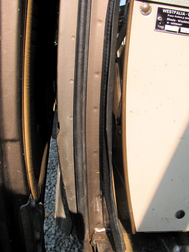
Finally… getting round to putting the innards of my ’82 Westy into my ’86 Syncro. Cleaning out the Syncro, the rear seats removed (boy they are heavy) and having a gander at just how much work it will be to put in the Westy stuff…
A few notes:
-the Syncro’s ECU looks like it was installed yesterday
– the rear heater had a bit of dried up coolant at one of the hose connections. I pulled the core just in case it was leaking too. The core had a date stamp of “00” so I am assuming it was replaced 10 years ago. Closer examination showed that the core was sound, but I swapped in a fresh one – an Iltis front heater core, same part number as Vanagon rear heater core – that I got at a govt. auction. The “old” core has a better construction method, the end cap opposite the valve covers return tubes, where as the “new” core I put in has the end cap being part of the return path… so if that end cap fails we get leakage.
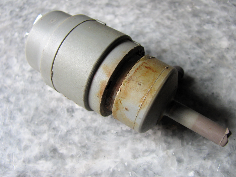
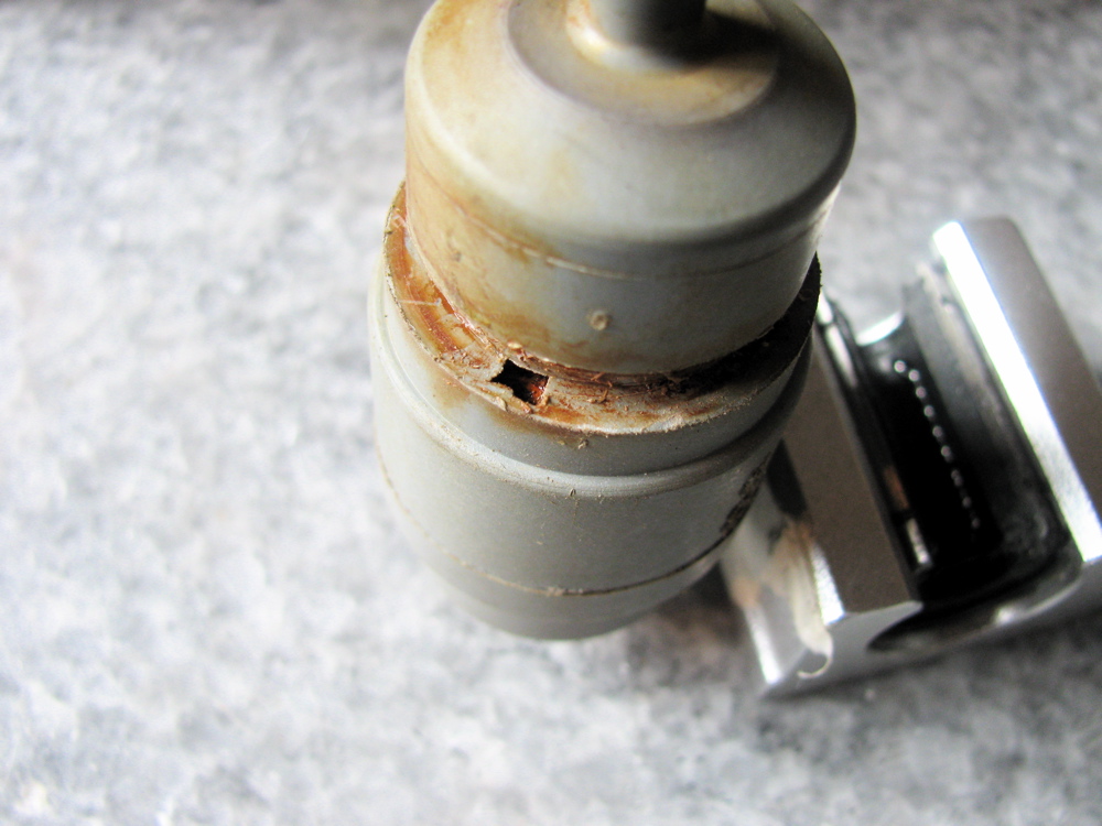
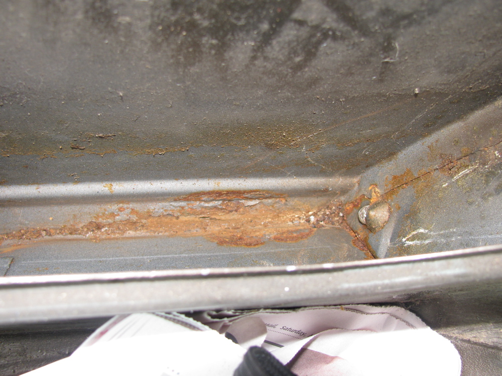
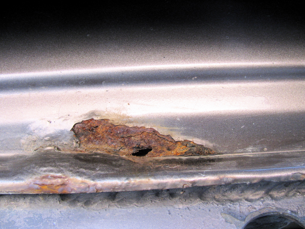
– leaking rear window washer reservoir had caused rust severe rust… Was like that when I got the van. To be precise, it was the pump that was leaking, I spent 5 minutes mucking around trying to seal the bugger, but hen found out they are pretty cheap and available.
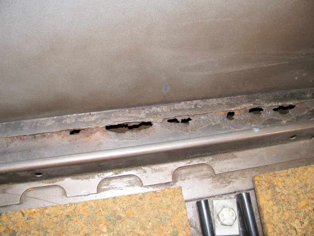
– rust on drivers side inner lower seam worse than I thought. Again, I know, I know.
– the rear bench sits in ok, and I measured the holes in the Westy were the hinge brackets attach to the rear deck and drilled in the Syncro deck (after cutting out a bit of the asphalt based sound deadening stuff). I tapped for a 6 X 1.0 mm thread (not much threading meat available on the deck, there must have been a backing plate on the Westy, I’ll see about doing same on syncro) and I screwed down the brackets. Well, it turns out that now the bench sits away from the pass. side wall more than it should. I remeasured the holes and found that on the old Westy the hole is 5 mm further inboard than on the Syncro. Funny eh? Both sets of holes are centred in the “same valley” . Something must have changed over the years. I have noticed that some Westys have a trim plate on the side of the bench, this might have been Westfalia’s answer to some body change VW made. I have one of those trim plates, I may use it.
-I tried the wardrobe fitment, and it looks like it will fit with no modification, even though I don’t have the Westy modified ceiling. The headliner might need cutting though.
-I tried a panel from Westy… I recovered most of the interior panels on my old Westy about 10 years ago, its held up well and I may re-use them.
Many other little details to iron out, but nothing difficult


