Archive for category vanagon mods
Vanagon – how much power do all those LED lights draw?
Posted by albell in vanagon, vanagon mods on July 4, 2013
So I’ve bedazzled the interior of the van with a mile o’ LED strips, how much power do they draw?
Full brightness:
strip over kitchen area = 0.37 A, 4.7 W
strip over sliding door = 0.39 A, 4.8 W
strip over lower bunk = 0.30 A, 3.1 W
pop top perimeter strip = 1.43 A, 17.6 W
total = 2.47 A, 30.2 W
(funny, power values differ slightly than what I posted back in Feb when I installed the strips over the kitchen and the sliding door. Due to the different controllers?)
With the PWM brightness controllers, the power consumption does go down when lights are dimmed.
For comparison, the stock fluorescent light above the sink found in some westies draws 0.9 A and 8 W. I don’t know what the power draw is with the stock light and incandescent bulbs.
Update: David and I were discussing (in the comments) white LED spectrum. He sent me the pdf file about that subject that is buried somewhere in the Cree website.
Vanagon – pop top canvas swap
Posted by albell in vanagon, vanagon mods on July 1, 2013
Long weekend here in Canada, and it was a warm one. Others might laugh, but out here on the wet coast hitting 30 C is warm. What better time to put in a different pop top canvas. The one I had on was from my old ’82 westy and it had seen better days. My wife had patched it up and replaced zippers but the time had come to give it some rest. Last summer I helped my friend do 2 canvas install and one of the old canvases was in pretty good shape. All it needed was a new bug screen in the window. My wife sewed in a no-see-um proof screen last year so it has been ready to go for a while. Why not put in a brand new canvas you ask? After all it is a pain in the ass to install the buggers. I am storing a brand new (Just Kampers brand) 3 window canvas for the aforemetioned friend, why not whip that in? First of all I think he would notice, secondly I like the way the stock VW canvas fits, the cotton material looks better than the Sunbrella versions inmy eyes (Sunbrella tops often drape like elephant legs). I guess the third reason is that the top was free.
As I was trashing the old canvas I went at it with a knife. Easier than dealing with the lower screws with canvas in place.

After hinges and lifting mechanisms disconnected, I rolled the top back on a long dowel laid across the van. Neighbour was called in to help lift the top onto a worktable beside van.

A couple of years ago when I painted the top, I installed what I thought at the time was a great idea, a fabric covered foam pad on the ceiling of the top. Well, this innovation was a dud, didn’t stay up, dropped, sagged, looked like ass. The idea of having a foam pad up there still appeals to me but I have to figure out a better way of attaching the foam (removable way). This time I went the expedient rote and bought some cheap indoor-outdoor carpet from Canadian Tire. It is very thin carpet, but it’s a not unpleasing texture and colour. The length is just enough to fit the top.

Just a matter of cutting to rough size and spray gluing it down, in stages, to the top. Went pretty well except towards the end (and I foolishly started at the rear) and the limited stretch of the material and my lack of skill created some wrinkles.

But if you squint, and have another drink, the wrinkles disappear.

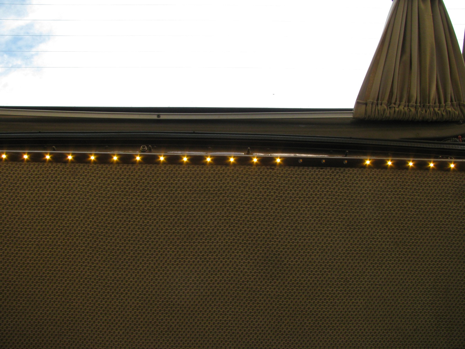
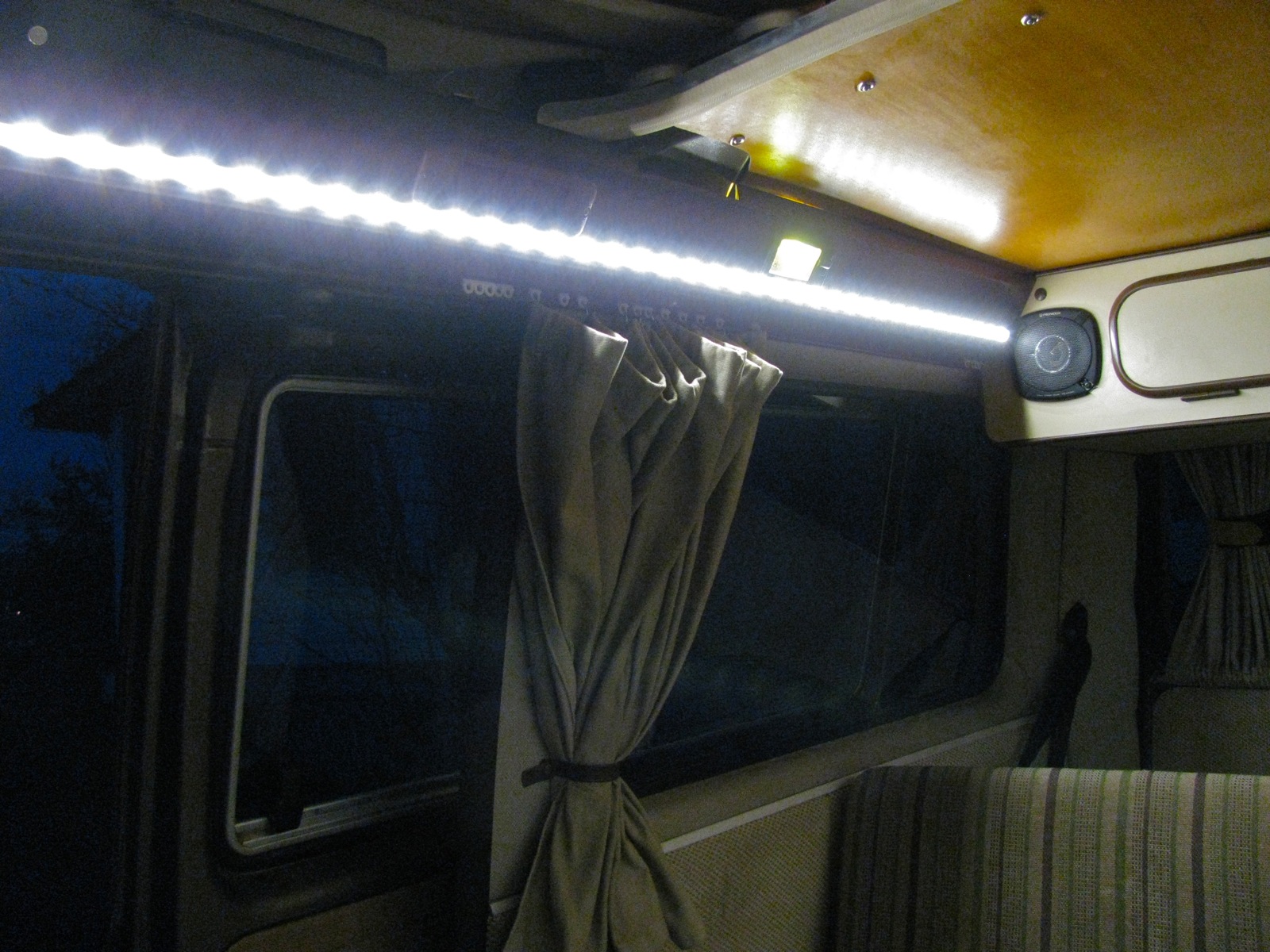
In the little space between the canvas and the ceiling I ran a strip, on all four sides, of LED lights.

I swear I tested them before I installed them, honestly. Little things like this really pisses one off. The photograph of the lit strips doesn’t really do them justice. It does make a good light up there, and the LEDs are on a dimmer so it doesn’t need to look like the Blackpool Illuminations all the time. I’d show you the wiring and controller but I’m not really happy with the wire routing (down the lifting mechanism) and I want to tidy it up.

Not a bad job, perhaps a little loose at the back, but sides and front are tawt.
One more thing… a little thing to hold a flashlight.

Vanagon – darned Dansk
Posted by albell in vanagon, vanagon mods on June 26, 2013
I had 2 niggling problems after the head R&R. One was a pushrod tube oil leak. Seemed to be on the case end of #1 cylinder exhaust valve pushrod tube. I don’t know why it leaked, perhaps I did not expand that tube far enough when I installed the heads? Or maybe there was some dirt on the sealing surface. I did install the seals “dry”, no sealant. So to fix this leak I pulled off the rocker arm assembly on that head, pulled the pushrod from that tube, and removed the tube (large tinsnips – collapsed the rube enough for it to fall out.). I cleaned up one of the spring loaded pushrod tubes that were originally on this engine and installed it, this time with a smear of Hylomar Universal Blue non-setting sealant.

The other problem, and this one had me worried, was a scraping, rattling noise coming from the engine or transmission. You couldn’t hear it if you were standing back at the engine and revving it, it only started when the engine was warm and the van moving. Clutch in or out, or in neutral, when I was driving and revved the engine this noise was there.
I could get it to happen when parked, if I had the parking brake on hard and slowly let the clutch out in 1st gear.
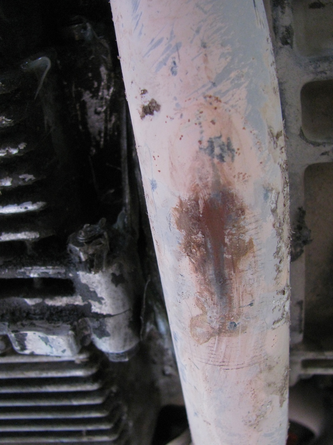
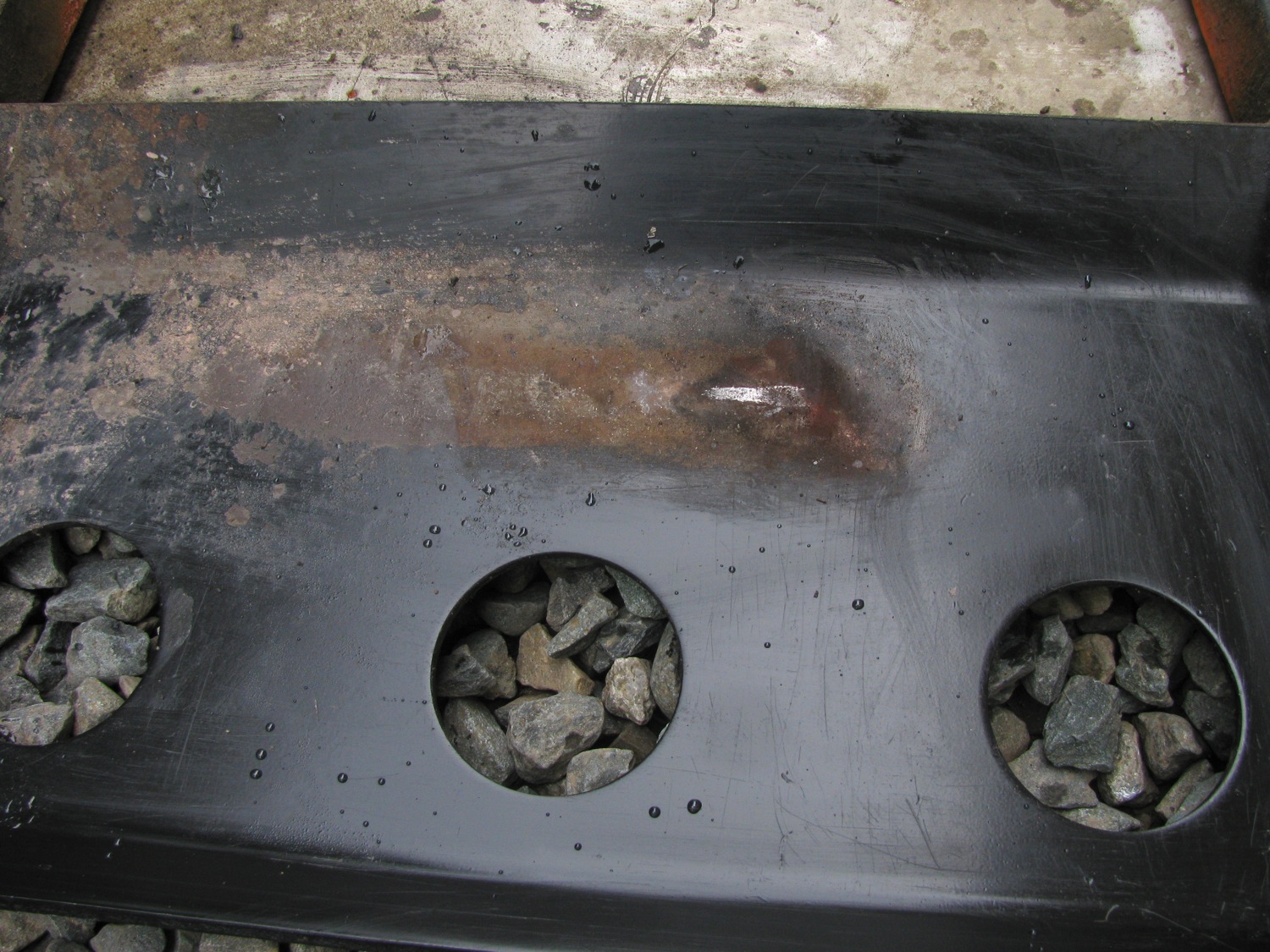
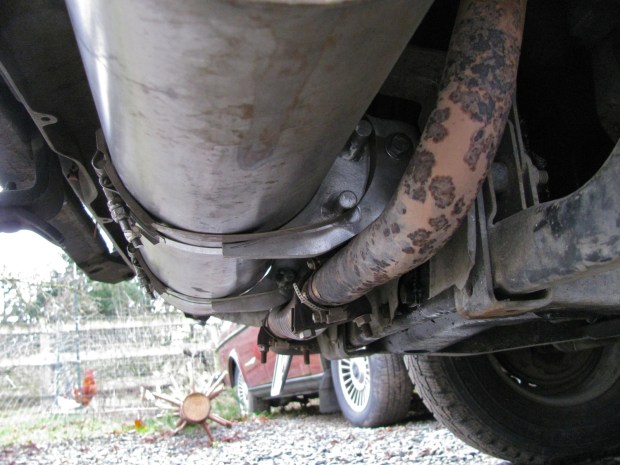
It really sounded like something was rubbing against something else. My rational side was leaning towards an exhaust pipe problem, my irrational side was making up all kinds of horrible scenarios. Well, it turned out to be the forward exhaust pipe hitting the skid plate where the pipe crosses under the engine. I’m going to blame the exhaust maker, Dansk, for this. My skid plate was not bent or damaged in that area. I think the pipe was just not bent correctly. I took a heavy hammer to the skid plate and bashed out some clearance.
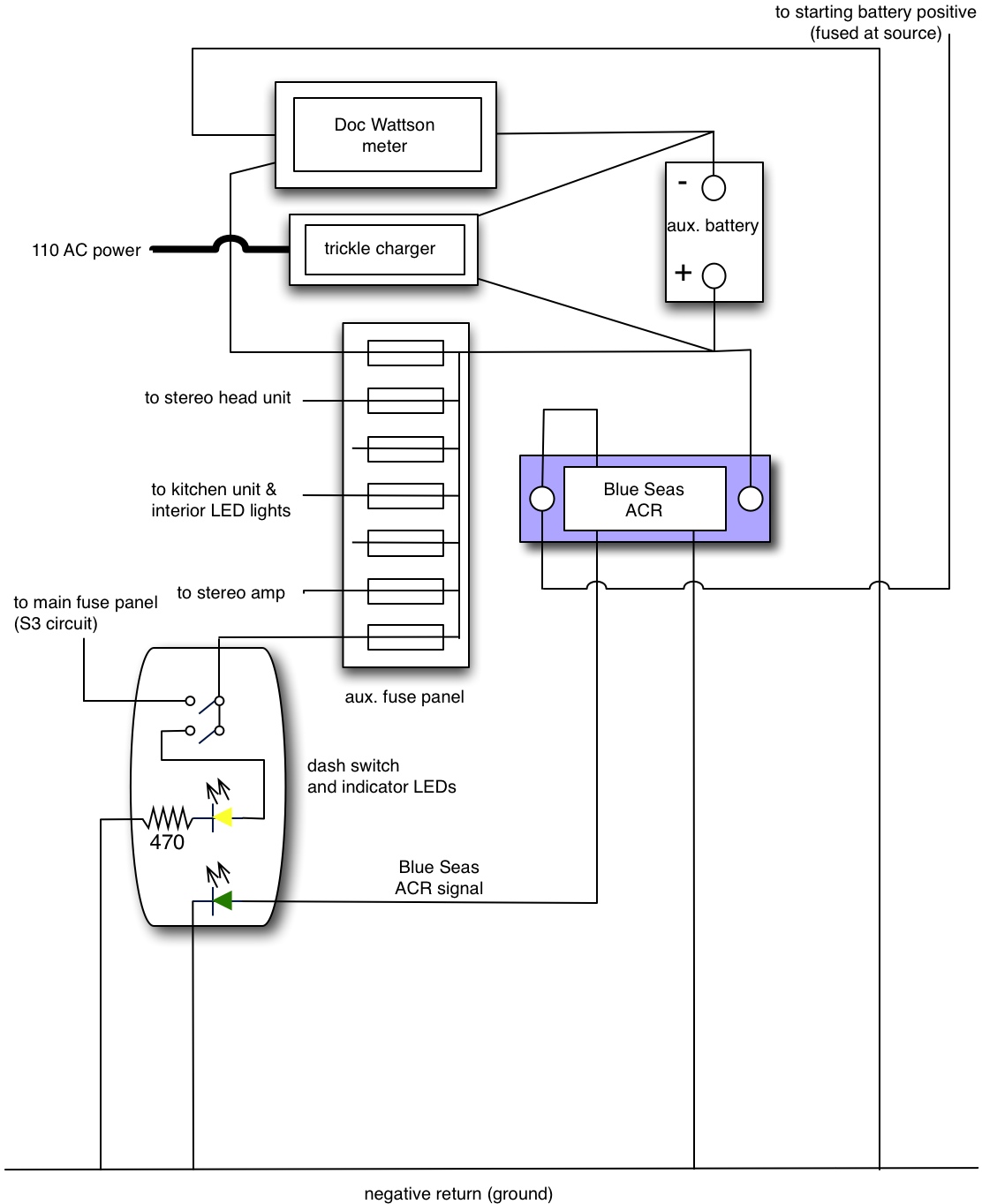
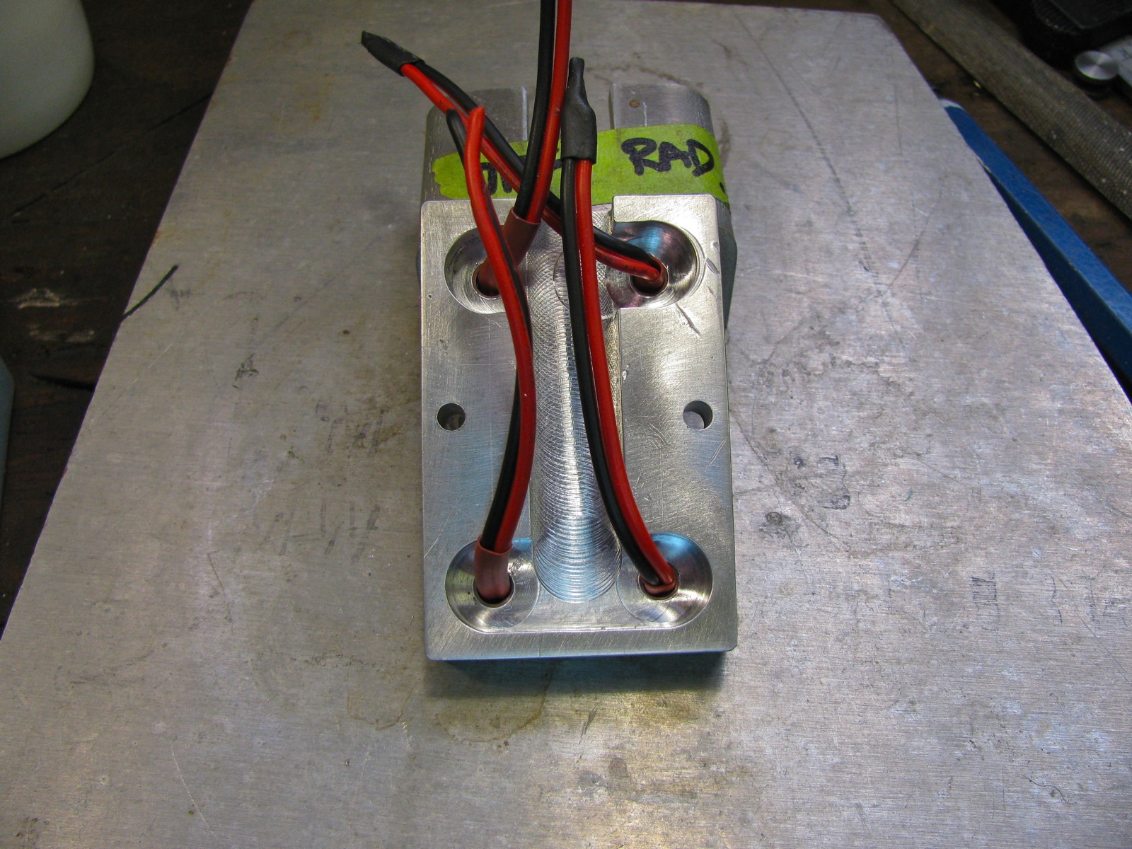
Vanagon – auxiliary fuse panel schematic update
Posted by albell in vanagon, vanagon mods on June 24, 2013
I have a confession to make. When I wired up that switch to shut off the door activated cabin lights it did not affect the additional lights (LED strips) I installed in the footwells and the step protector. Had me puzzled for a while, I thought I had connected those lights to the map light feed which I thought was the same feed that the other lights were on . The Bentley wiring diagrams didn’t help until I looked at the “after 1990” pages. Turns out that the map light gets its power from a different feed (but still protected by #3 fuse). So in order to be able to switch off those lights independently of the door switches I would either have to intercept the power feed or simply intercept the power going to #3 fuse.
This post describes how I feed the circuits on #3 fuse from my auxiliary battery. And in this post you can see how I subsequently powered the radio with its own feed. So all that was being powered on #3 fused circuit was the map light, my footlights, glove compartment light, and the cig. lighter. Easy to see that putting a switch on that circuit would do the trick. But wait you say, won’t you want to have the cig. lighter powered all the time so that you can plug in a USB charger or something? Well, yes, I suppose. I’ll see how it works out. I’m wanting to add more power points in the van, the cig. lighter may become redundant.
I went ahead and rewired the switch. Here is the updated schematic.
Addendum: cutting power to #3 fuse circuit also cuts power to the dash clock. I can live with that, I have plans to hard wire the dash cluster due to a very deteriorated instrument foil.
Vanagon – sliding window felt and interior light switch
Posted by albell in vanagon, vanagon mods on June 21, 2013
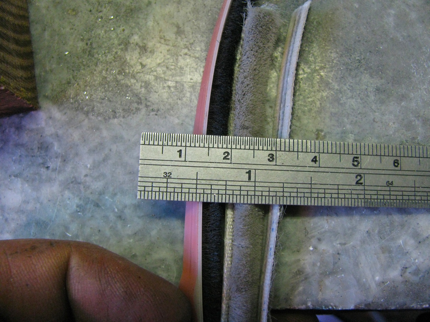
A couple of small things. First off is replacing the window felt in the sliding windows. You can only get at the horizontal felt with the window in the van. But if the entire window is out, then the frame can be spread and the sliding portion removed and you can get at the vertical felt seal. I found some felt seal at a local RV supply store, and I think that auto glass outfits can supply it too. I looked in the hardware store at some patio door felt seal but it wasn’t quite the right size. You might have better luck.
So open your window and at the forward end pull out the rubber seal a little, just so that you can get better access to the seal. Grab the seal and slip it out, little by little as it has to make a sharp turn out to get past the window frame. My old seal was very worn and brittle, kept breaking as I pulled it out. The new seal goes in the way the old seal came out. It is easier than it looks.
The new seal is so much fluffier than the old one and the window initially did not slide very easily. But after a day the felt compresses a bit and sliding is easier.
Picture time. Three felt seals: on the left is the new seal (yeah, not the same colour), middle is a bit of what looks like unused original seal (lord knows where I got it), and on the right is the old seal.

Back side. And yes, the new dark seal has an peel off backing, adhesive under. I din’t have any problem installing it with backing on.
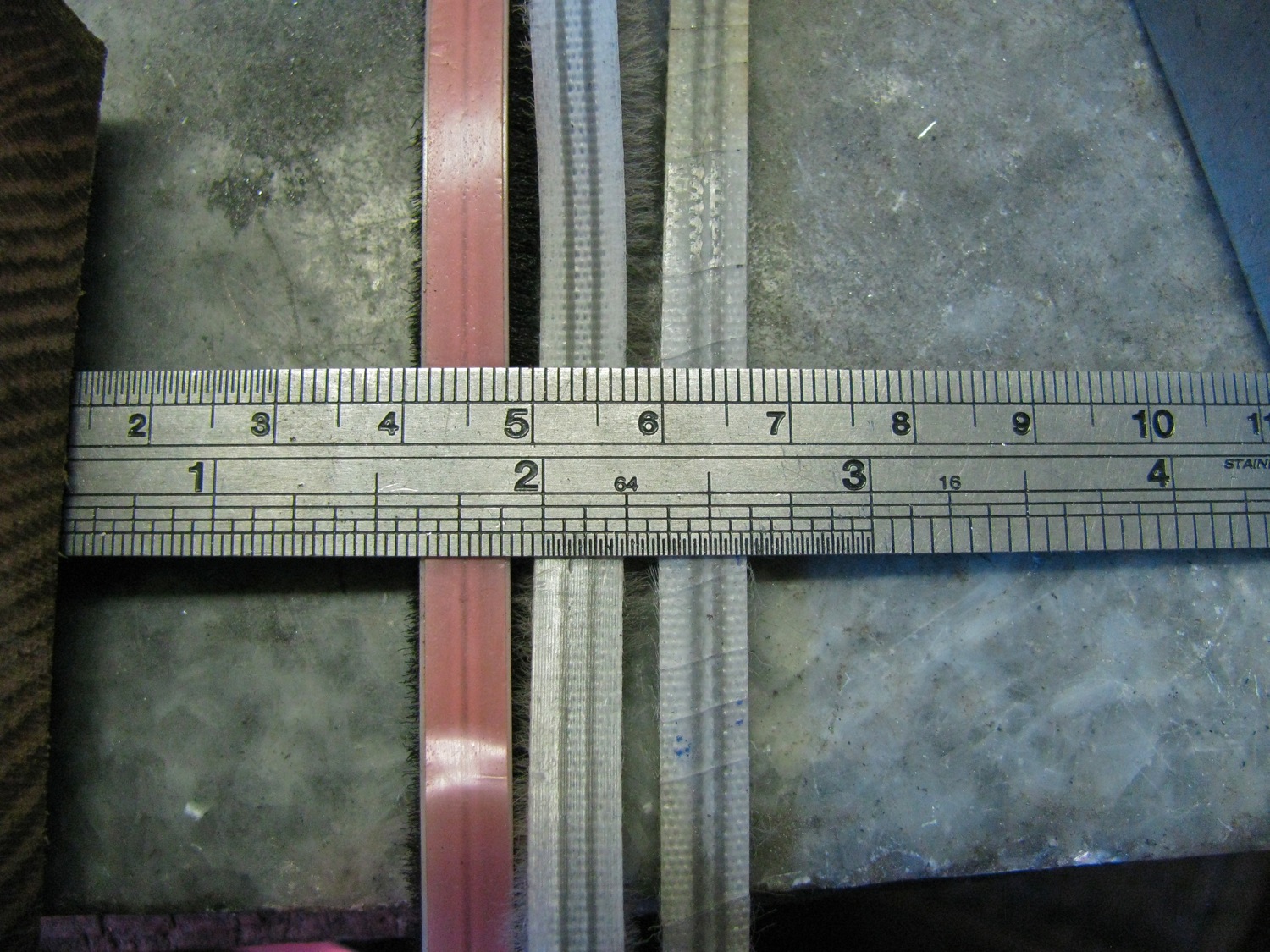
An attempt at a side shot. The old seal is very worn out.
Installed. The dark colour is not that bad.

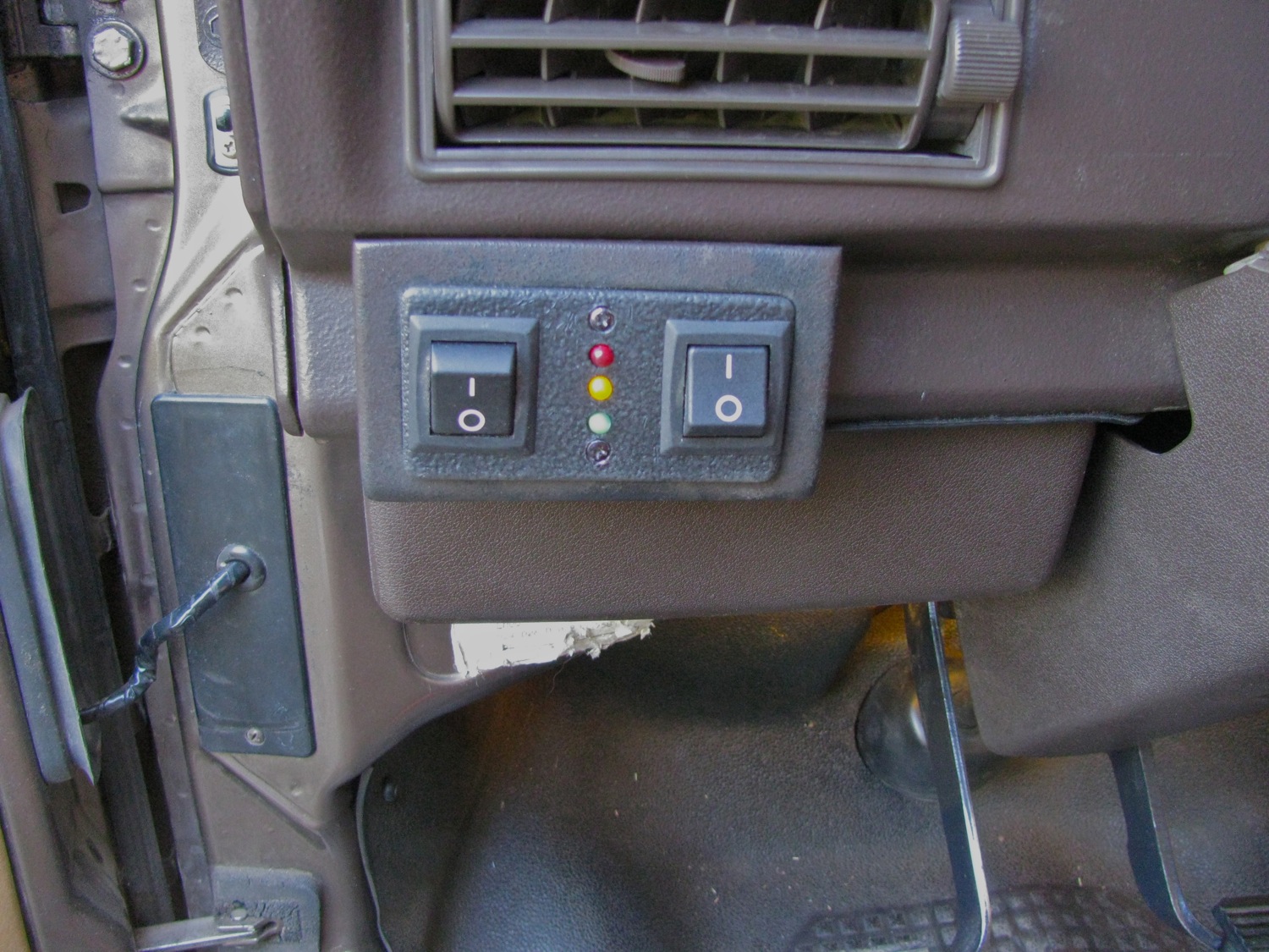
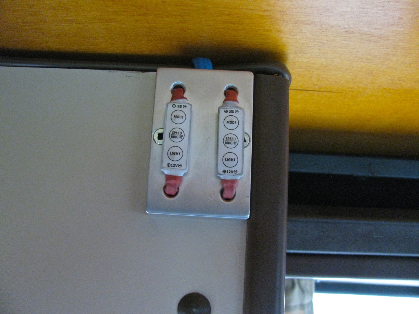
Next up is a silly little mod. My van was originally a 7 passenger tin top and so it has interior/cabin light switches on all doors, including the hatch. Factory Westies do not have door switches on the sliding door and the rear hatch. So what you say? Well, when you are camping, and you have the sliding door open then the interior/cabin lights are on whether you want them on or not. Kinda silly during the day, and not really needed at night if you have added lighting on a different circuit. Of course you can turn off each individual light, or you can find some of those door switches that have the little notch in the plunger so you can have the plunger stay depressed, but jings, where’s the fun in that?
So one evening I made a little switch plate to fit where my old Webasto BBW46 control panel was (I gave up on the heater, removed all the plumbing during the head replacement job). I didn’t use the sexiest of switches, but they are what I had. I used two just because one switch looked silly. And the two switches left an awkward space between them, so I added some LEDs.
So what I did with the wiring was to intercept the power wire to the interior lights (on my van it comes out out panel from B12 connection, then splits at connector T2c. That power feed also supplies radio and make-up mirror light. I did not have to worry about power to radio, I’m supplying it another way. Ok, I cut that power feed and connected it across on of the new switches. Just for fun I wired in the amber LED to light up when switch is closed. So to turn off all the door switched lights I just have to flip one switch.
The green LED is connected to my Blue Seas ACR and lights up when the main and auxiliary batteries are combined. The red LED is still waiting for a use, as is the other switch.
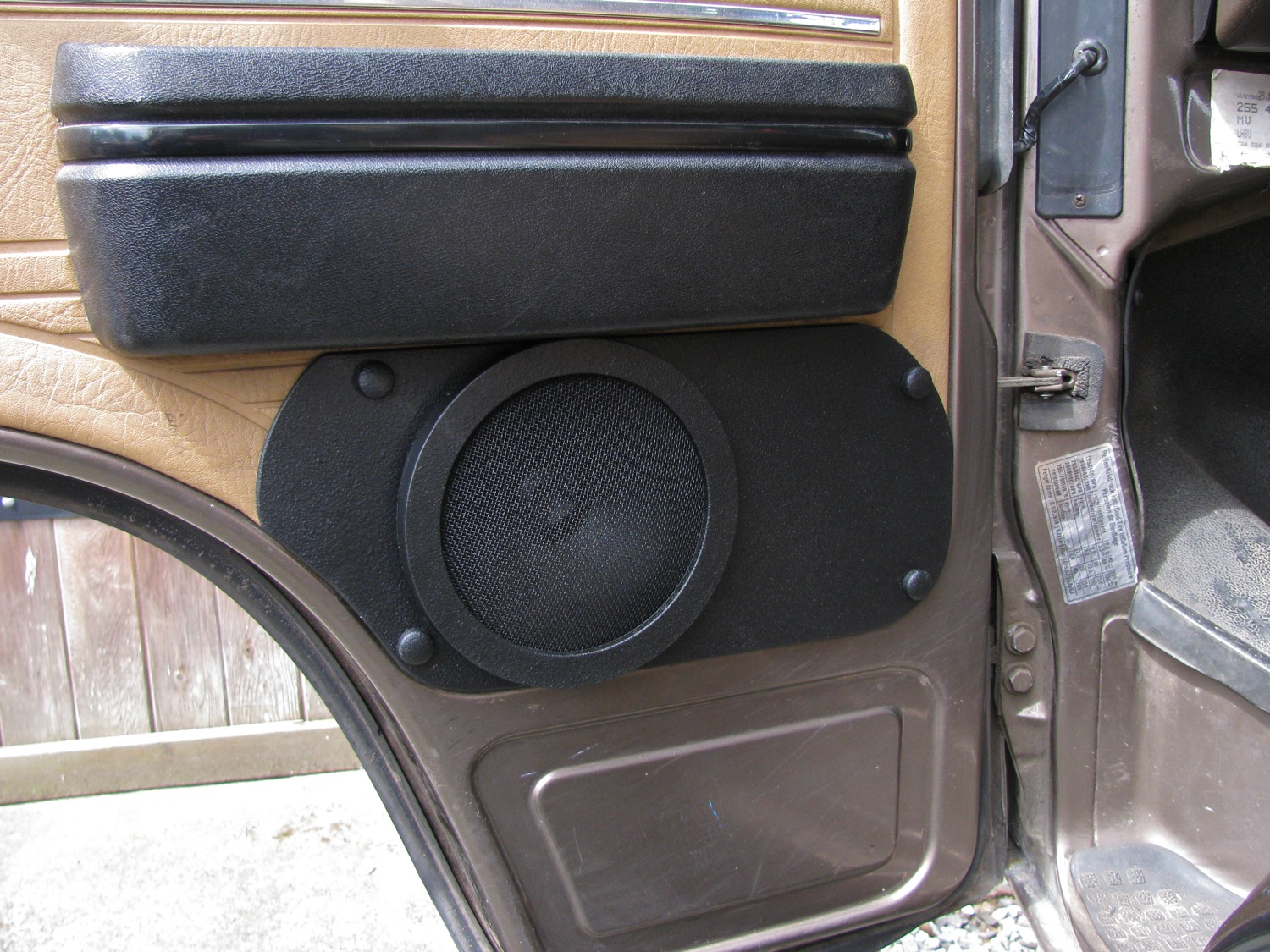
Vanagon – front door speaker mounts – painted
Posted by albell in vanagon, vanagon mods on June 18, 2013
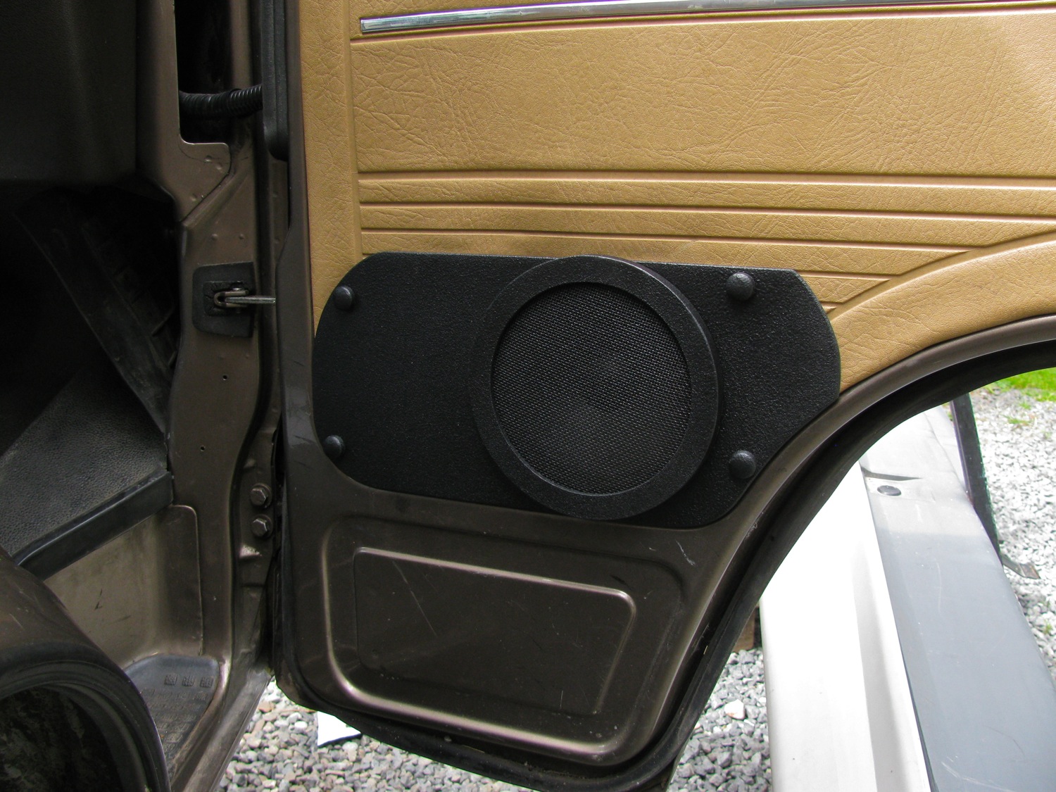
A year ago I made some speaker mounts to help hide the torn up lower half of the front door panels, and to mount the speakers more securely. It was a previous owner that installed (and cut some door metal) these speaker and it really wasn’t a very good job. My solution worked out ok, but I tired of the unfinished aluminum look and the speaker grills had been kicked repeatedly and were dented. I can’t really blame anyone for the kicking, the speakers are in a vulnerable spot.
So I pulled them off, took them apart, and reformed the stainless mesh grills back into a shallow dome. Then I painted everything with rattle can bed liner. I think the paint stiffens up the stainless mesh, gluing the wire crossings. I painted some plastic screw cap covers to match.
Original look:

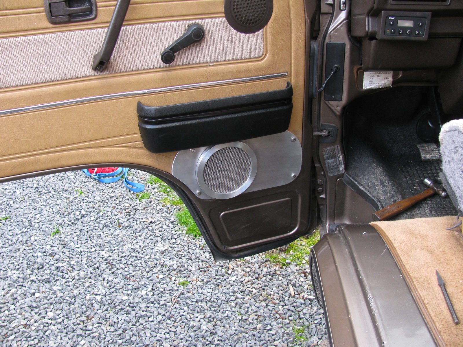
New look:
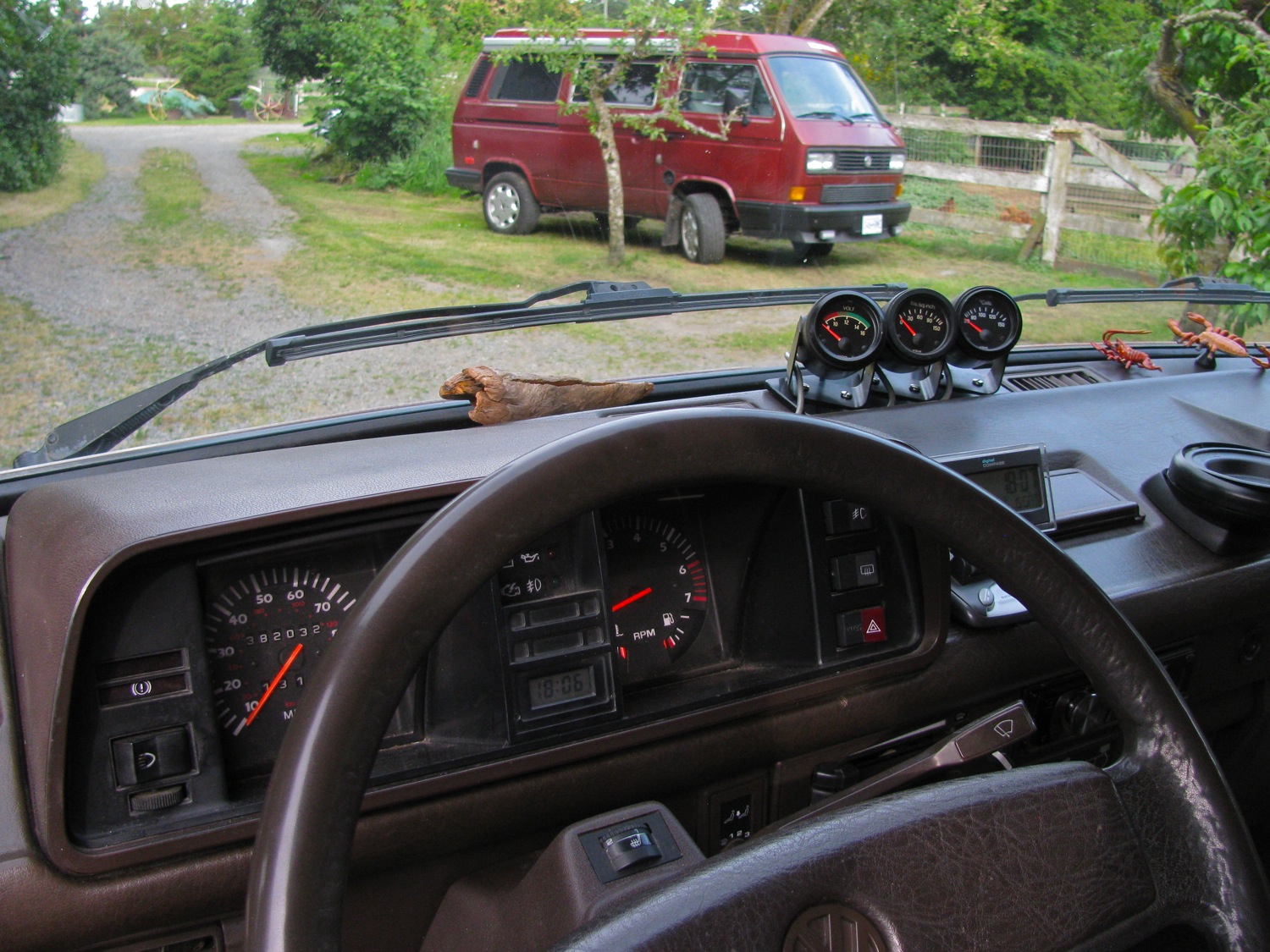
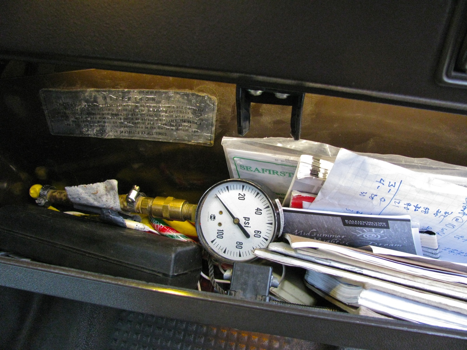
Vanagon – auxiliary gauges
Posted by albell in vanagon, vanagon mods on June 18, 2013
I installed 3 old gauges, VDO Cockpit series, that I had in my old I4 powered ’82 Westy. It was sure easier to install the senders in that engine, no relocation manifold needed. But on the WBX I had to relocate the stock oil pressure senders so I could add an oil temp. sender and an oil press. sender.
I detailed the sender install in this post. That short temp sender (Beck Arnley part# 201-1098) seems to be the right one, the oil temp gauge is indicating pretty well expected readings. Yeah, yeah, I should have set up some boiling water and tested before installation. But I didn’t, so there.
Hey, if anyone has a mind to copy the aluminum manifold for the senders, give more room between each sender. I put them too close together, wrench access not so great.
The gauges have seen some wear and tear, and I replaced the bezels on two of them with bezels from salvaged gauges from an old Volvo 245 turbo. The bezels are crimped on so removing them means prying with a fine edged screwdriver and you can’t really get that back to factory condition. But from a distance it is not really noticable. During the bezel replacement I dropped 2, yes 2, of the glass faces. What a clumsy fool. I had one spare glass, and for the other I cut a circle of Lexan. I repainted the needles with fluorescent orange paint while I had the chance.
For wiring I used some old computer cable, 6 insulated wires in a grey sheath. Each wire was multi-strandded and the sheath was pretty flexible but I bundled the 3 cables in some black heat shrink tubing and the bundle is pretty stiff. I used a heat gun to warm up the bundle so I could manipulate it into the right route. And that route runs right in front of the padded dash to the corner of the instrument panel cover, where I made a rounded notch and the cable makes a 90 degree bend and a little down to end up close to the right hand side dash support strut. The bundle lays down with no glue or clips after the heat gun treatment.
At the sender end, I used a couple of spare wires from the now removed Webasto BBW46 heater wiring to send oil press. and temp signals up front. For the voltmeter signal I connected to “G5” terminal on the fuse panel (“15” power, ie hot when ign on). For illumination, I tapped into “G8″ (dimmer controlled power) on the fuse panel. To make things a little neater, I used an old terminal strip that has screw connections and used that to connect the gauge wires to the sender wires. This terminal strip was mounted to one of the dash support channels beneath the instrument panel.
The gauge pods were screwed onto a bit of 1/4” aluminum plate, painted black. One day I’ll get some black covers for the screw heads. The plate is glued to the dash with that foam cored double sided tape. That stuff seems to take dash heat better than other tape . The gauges seem to work fine, I didn’t confirm the oil temp or pressure with another method, but the values I see look reasonable.

Vanagon – small finds at the auto wreckers
Posted by albell in vanagon, vanagon mods on May 15, 2013
I had the afternoon off so I drove up to Malahat Autowreckers to see if there were any new Vanagons in stock. And indeed there were, 2 1990 MY passenger vans that were not completely stripped. One was a weekender, driver’s side jump seat and table still intact. Both had something I had not noticed on a Vanagon before, an aluminum sill plate on the sliding door entrance. I bought one, here it is.

The part number is 255 853 558. I think it is available from VW Classic parts, “scuff plate – sill panel- Einstiegleiste”,
Back side:

I also managed to find a couple of undamaged cup holders.

And some fairly new looking front door inside latch plates (they really get ratty, especially the brown ones), and a couple of surrounds.

A few relays and clips rounded out the shopping spree.
Vanagon – misc. updates
Posted by albell in vanagon, vanagon engine swaps, vanagon mods on May 14, 2013
I haven’t been posting much recently, work and garden chores have been taking my time. One good thing about the work time is that my welding is slowly improving. Helps having a good teacher and access to the best equipment. One day I might be able to make a good aluminum weld that is more than one inch long.
But some things are happening on the vanagon front. First off, I replaced the LED light strip on the rear of the lower cabinet, doing away with the pierced moulding experiment. Mainly due to the fact that 6 LED elements failed on the initial install, but also I didn’t like how I drilled the holes. The LED strip is in an anodized aluminum channel


Staying with LEDs, I installed a couple of feet of strip above the footwells of the front seats. They are wired to go on with the doors opening. Not the greatest mod in the world, but fun to do.


When I was younger I thought that ski boxes, or coffins as I dismissively called them, were stupid. But what do you know, I’ve changed my mind and I found a really old school Thule Combi-Box 250 for sale for $50 and I bought it. So why the change of attitude towards these things? In a word, chairs. Yup, I’m fed up with stowing the folding camp chairs behind the back seat. Now they will go up top, and the fishing rods too. I haven’t mounted the box to the van yet, I still have to make some modifications to my roof rack attachments so I can get the box on the right spot on the roof.

The bigger news is that I was given a 2008 Subaru EJ25 motor. Good friend Simon had it in his ’91 syncro and it had been making a brapping clstter upon acceleration. All kinds of things were tried to stop the noise, none of them worked and the final opinion that it was perhaps a rod bearing. So he swapped in another engine and gave me the suspect one.
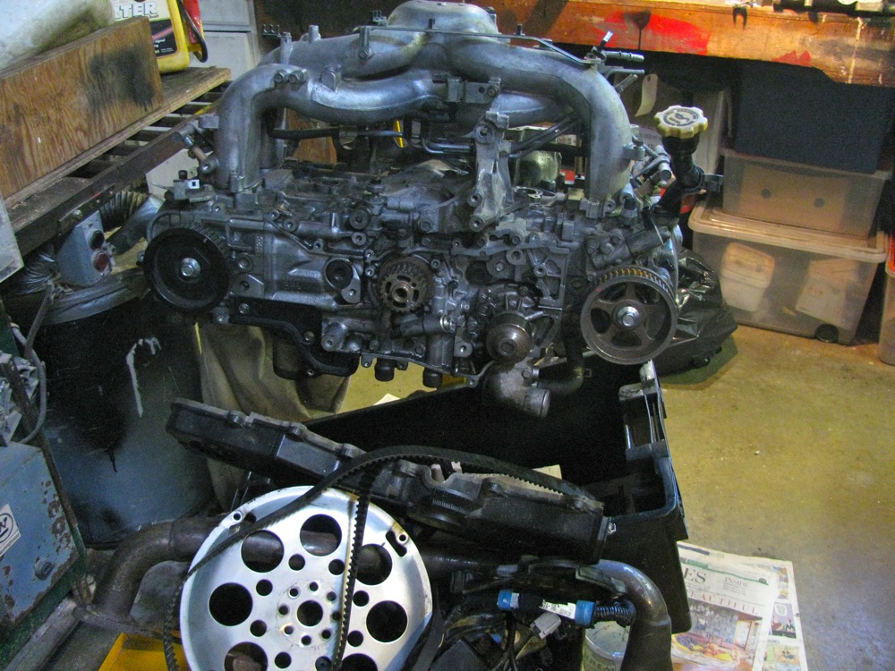
The generous gift has put me on the spot about future engine transplant. I really have a soft spot for VW inline 4 engines. I had one in my ’82 van (1800 Digifant) that ran flawlessly from 1994 to 2009 (van got T-boned and written off). I’ve been nursing the idea of a 2.0 litre I4 in the syncro. I have all the parts needed except one of the big ones – a diesel gastank. The starter in the 12 ‘o’clock position with the diesel bellhousing so it needs a differently moulded fuel tank to clear the starter. Those tanks are not so common over here on the northwest coast of North America so I haven’t been very quick to get an I4 installed. My dawdling and initial lack of interest in my stock WBX engine has resulted in me not doing much about keeping my current motor in good shape. Bothe the front and rear exhaust manifold need replacement, but the studs.bolts holding them on to the head are really rusted and decayed. I know that they will be hell to remove. Plus I have a slight coolant leak on one head (happens during cold part of winter) so it means some sort of head work even without the exhaust problem.
But then again I have a spare WBX engine that I have been just dicking around with. Why don’t I take the heads off it and see if they are good enough to use on the van’s engine? That way I can replace the exhaust manifold and head leak relatively quickly and keep the WBX in my van running long enough for me to get the Subie engine attended to (or get and I4 built up :)).
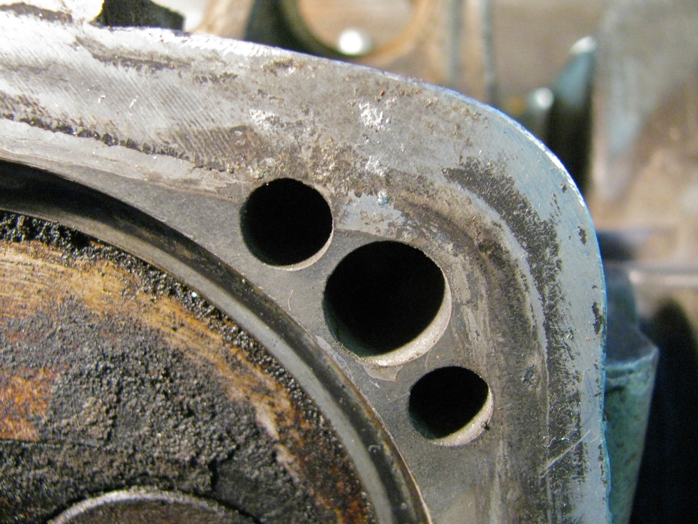
I had to drill out a couple of the exhaust studs on the spare heads, nothing, not even oxy-acetylene heat would budge the buggers. One of the drilling out operations went awry and I had to fill the hole by tig welding then re-drill and tap.
So far the heads look usable. One head has pitting, the other does not, just a hint of some corrosion beginning.
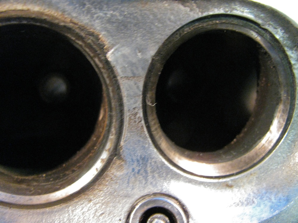
The two heads, I took a wire brush to one, and removed one set of valves (valves check out ok, and within spec on fit in valve guides).

Close ups of the pitted head.
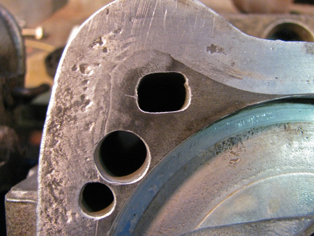
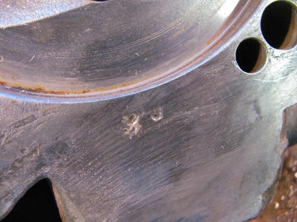
Doesn’t look like any crack between the valve seats.
But is that a casting mark or a closed crack? I don’t think it is anything to be worried about.
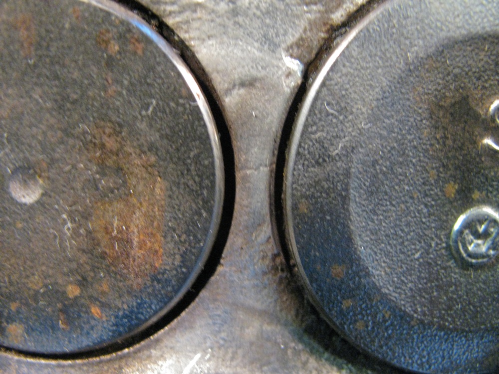
The start of some corrosion on the un-pitted head.
And example of what the rest of the sealing surface looks like.

So I’ve got these heads, a gasket kit, a new front exhaust manifold and a used rear manifold. The plan is to drop the engine and tranny (I want to fix the diff lock light switch on the tranny, easier if tranny is out) and swap over the heads etc. I hope to do this in the next couple of weeks.
Vanagon – interior LED lighting update
Posted by albell in vanagon, vanagon mods on March 29, 2013
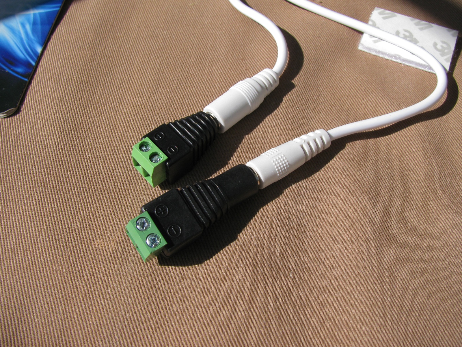
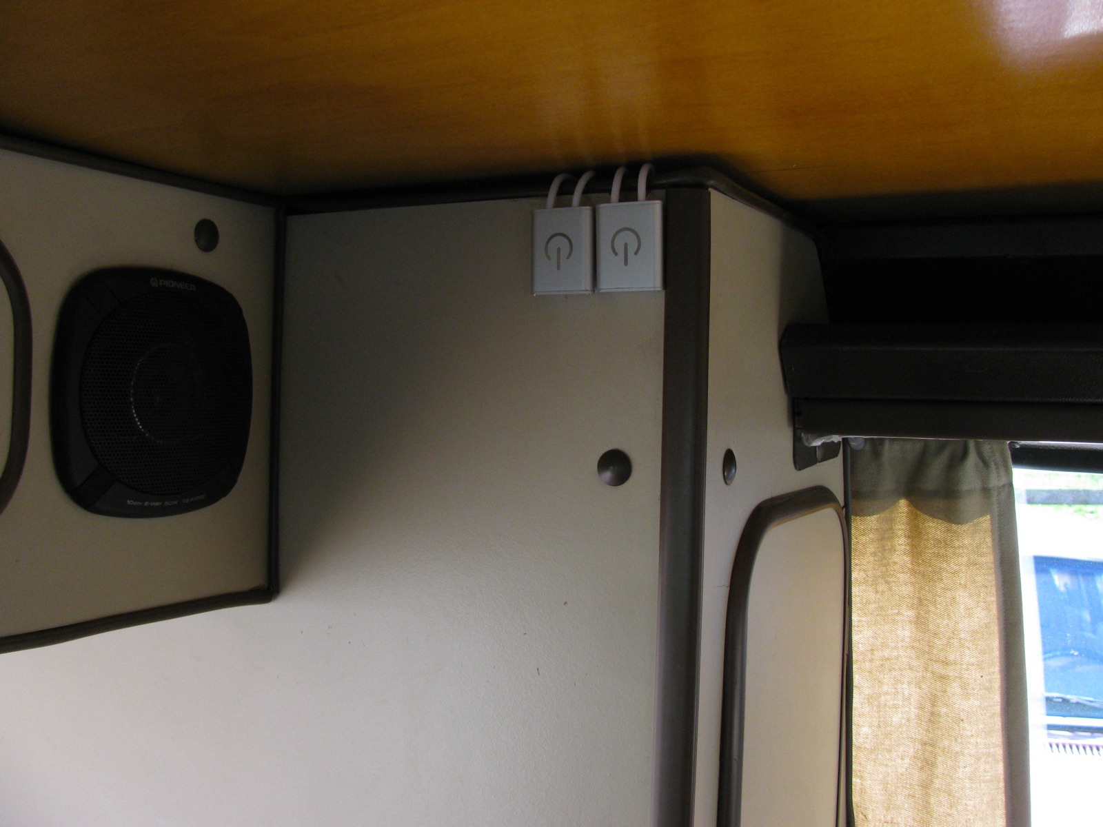
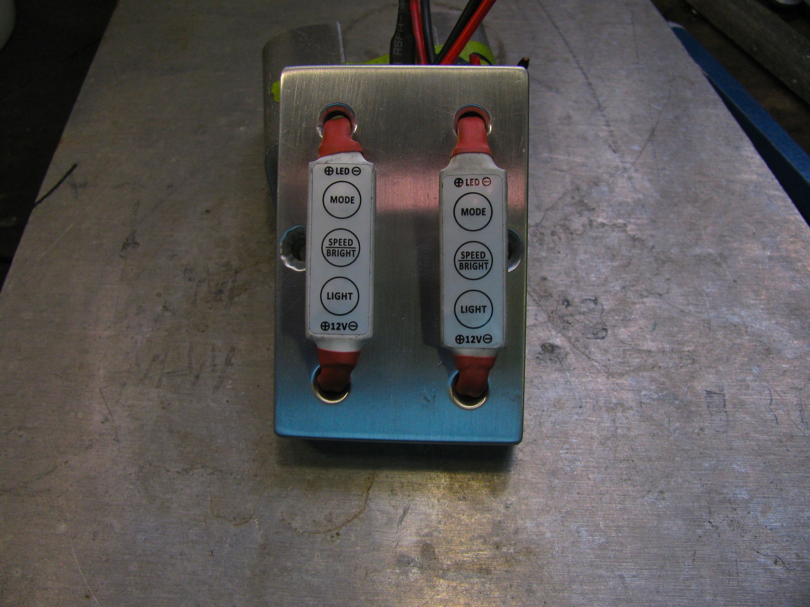
In this post I described installing some led strip lighting and dimmer switches. During the install I smoked one of the dimmer switches so I wired both strips to the one controller and lived with it until I ordered another switch. Those dimmer switches were inline units and I spent some time milling out a kind of mounting plate for them. The more I looked at this kludge the less I liked it. It didn’t help that a couple of friends were less than enthusiastic about it, despite my glee at actually being able to make the thing. Looking around superbrightleds.com I found a better solution, this dimmer switch. All it does (capacitance touch method) is turn light on and off and dim them. The previous switches had additional flashing and flicker settings which really are useless in this application ( I thought perhaps the flicker setting would mimic candle light – ha! was I wrong).
The new switches come with 5.5 mm barrel connectors so I also ordered up some adapters so that I could attach wire pairs. I installed the switches today and I have to say they are a big improvement over the other ones. One touch turns the light on or off (and the light ramps up and down with the on and off touch – a small feature but very cool), and holding your finger on the switch dims down then back up. No moving parts, its all to do with capacitance (David B. needs to explain this to me).
No points for guessing where the makers got their design influence from.

The male and female 5.5 mm barrel to wire adapters.

The wires go here 🙂

Adapters on the switch leads.
The switches come with a small square of 3M adhesive backed Velcro. Makes them dead easy to mount, but not dead easy to get two of them perfectly aligned.
Addendum: I just measured the current draw of the new switches. When turned off my Do Wattson shows 0.00 A. When both main cabin strips turned on the meter shows 670 mA. This is better than the old switches that did consume a little power when off (somewhere under 10 mA) and when switched on the system drew 750 mA.
Vanagon – platinum catalyst heater mount
Posted by albell in vanagon, vanagon mods on March 26, 2013
Yeah, I know, I know, these heaters are not the best solution for the van. I got this one back in ’93 and never did install it in my ’82 westy. But over the last couple of years I’ve dragged it out to use in the syncro for winter camping, and last week I finally cobbled together a more secure mounting system for it.
BTW, apart from the risk of oxygen depletion, and the possibility of CO production (although if the heater is working properly little CO is created, well except if the oxygen level is low then more CO is produced) the big drawback of an unvented propane heater is the production of water vapour. Here’s the logic, using a 1 lb propane bottle as fuel source:
combustion equation:
C3H8 + 5 O2 —–> 3 CO2 + 4 H2O
so for every mole of propane burned, we get 4 moles of water.
the molecular weight of propane is 44 g/mol, and therefore a 1 lb (454 g) bottle contains 10.3 moles (454/44)
So burning the entire bottle would produce 4(10.3) = 41.2 moles of water
The molecular weight of water is 18 g/mole, therefore 741.6 g of water produced.
A respectable amount, almost 3 cups, of water is liberated into the van when you burn a one lb bottle of propane.
So the lesson learned is either buy a vented heater or make sure you vent the van well. I like to have the pop top vent partially open and one window open about an inch when I use my unvented heater.
OK, enough. The point of the post was to show my quick and dirty mount. I used scrap 1/4″ aluminum (5052 if you’re asking) and instead of welding (my skill at welding inside corners, especially on tubing is still at the crap level) I bolted it together.
The heater.

The unpainted aluminum shape is bolted to the heater to stiffen things up. The painted “wing” is the bolted to that stiffener. The bent tube is actually bolted to the wing – bolt through wing into a tapped hole drilled crosswise in a bit of steel rod which is running crosswise in the tube. Oh yeah, that’s great descriptive prose. One unexpected bonus is that the heater now can be placed on floor, if desired.


Unpainted end of tube fits into front table arm of the van. It can be adjusted to a range of positions and is high enough to mostly avoid being hit by the dogs.

I’ve been using a 20 lb propane bottle sitting in the driver’s footwell. No, not the most elegant solution.
Addendum – it just occurred to me that it might strike some as strange that I don’t simply attach the tubing directly to the stiffener piece and get rid of that black wing. The truth is I made the tube and wing first and mounted it directly to the top two bolts on the heater. But I found that not steady enough so I made a backing plate. I liked how I could coil the propane line around the wing, so I kept it, for now.
Vanagon – an interior led lighting project fail
Posted by albell in vanagon, vanagon mods on March 16, 2013
It’s not hard to guess that I am enamoured by led strip lighting, but my latest project using the strips is a (qualified?) fail. I’m posting it just to make it clear that I often go down wrong paths.
I had some led strip left over from the step protector project, and I wanted to get some light back at the hatch area. Sometimes we sleep with “heads at the hatch” (more of a summer rather than winter position, but what the heck do you care? :)) and It would be nice to have a reading light back there. A light also could be useful for finding stuff in the dark etc. So how to mount a strip of led lights back there? Well of course a bit of aluminum channel screwed to the back edge of the ceiling – in place of the T moulding – would be the way to go. But I decided I was smarter than that.
I took the T moulding off and went about hacking it up to install the leds actually in it.
The Westy T moulding.
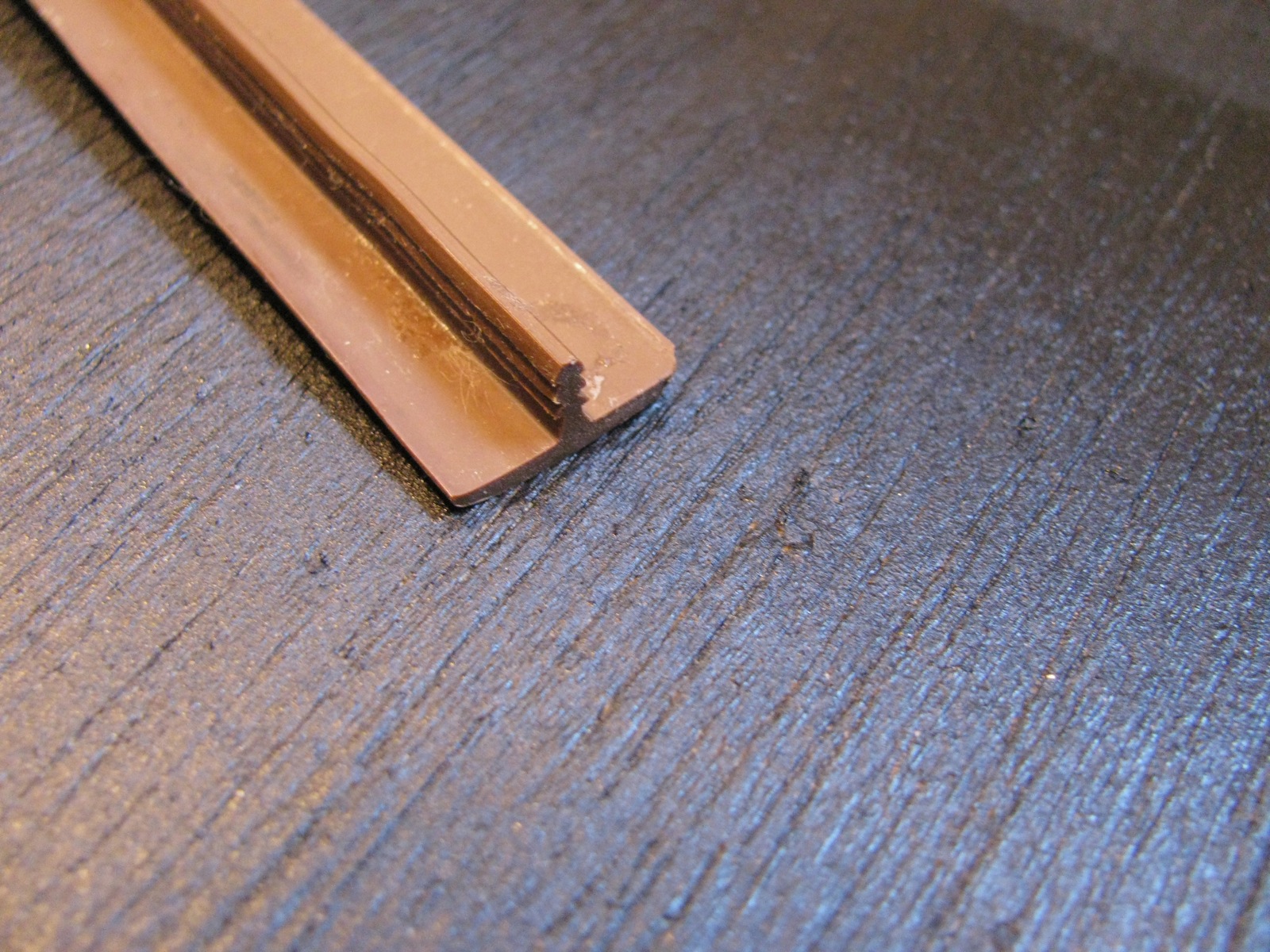
The led strip, looks like it will fit behind moulding if T was removed.

After some false starts, I found that my die grinder with a ball end bit cut the T off nicely.
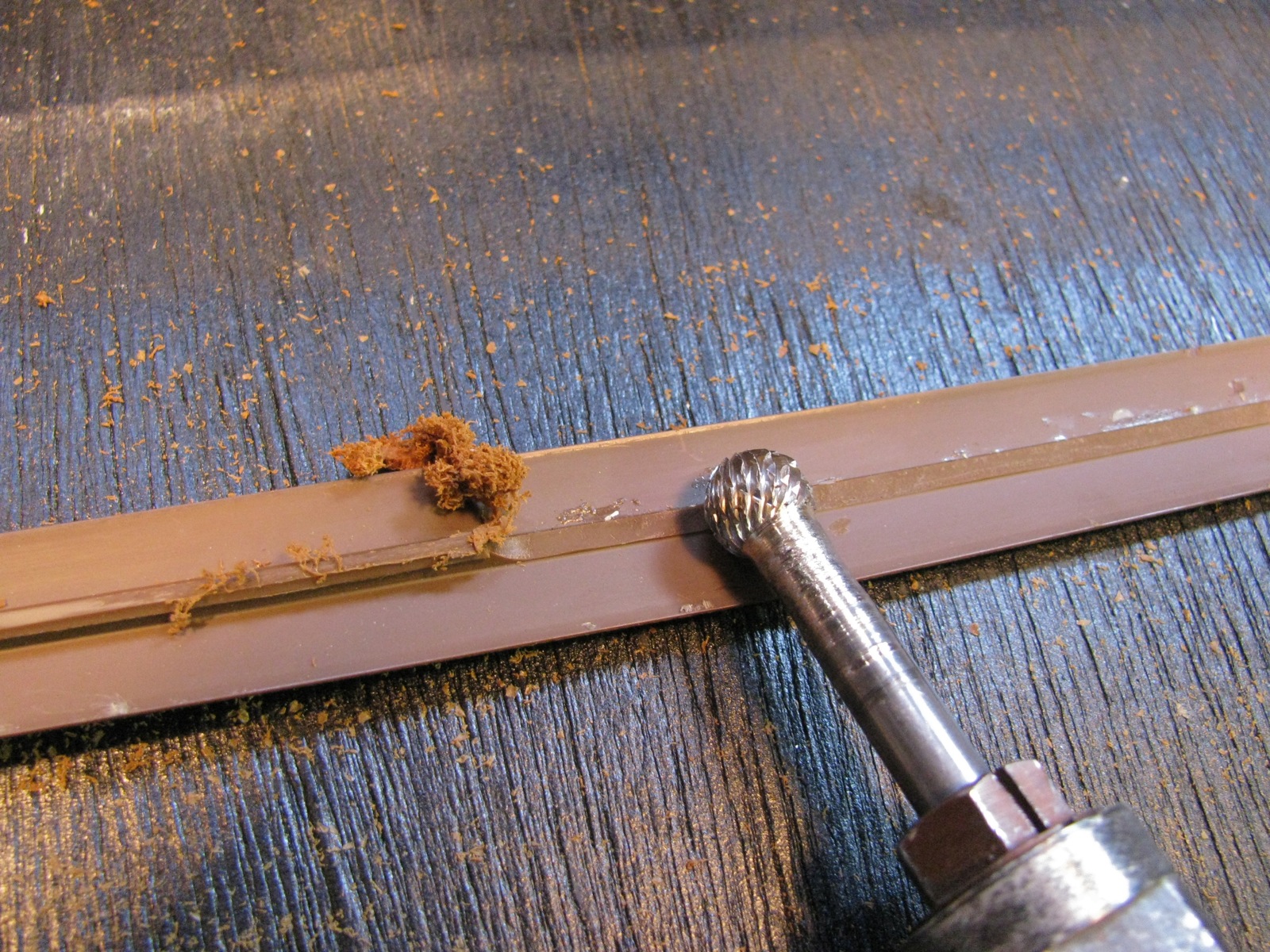
Ok then, done.

The next part was to drill holes for the leds to peek through. Now I don’t know what system the makers were using to space the led elements, certainly they weren’t thinking about me laying out for drilling. And, every so often the spacing changes as strips are factory joined together. Grrr, I had to drill holes larger than I wanted too. But I kept on going down this path and I glued the led strip face down onto the T moulding.

Right then, after the glue had set I took the strip out to fix it up on where it used to be. I have no pictures of the shambles that followed, but imagine the floppy strip, Sikaflex, no real locating mechanism to keep strip from sliding sideways, spring poles that kept falling…
But up it stuck.

It looks much worse in real life. Here is side view.

So what are those aluminum bits at either end? My attempt at hiding areas where the laminate had chipped off the plywood (nothing to do with this project) and to securely hold down the ends of the modified moulding. During the project I had glossed over the question of what kind of switch to use and where to mount it. I tried but came up with nothing better than this switch mounted on a little but of angle glued to side of upper cabinet.

It is not great I know, but there you go. And switching on…
Bloody hell, 3 leds out. I’m sure that when I tested the strip before gluing it on to the cabinet all of the leds worked. I’ve resolved to rip this out and re-do using aluminum channel and new led strips. Will the night time shot make me feel better?
Couldn’t wait until full dark, pics taken at dusk. First one, light off.

And light on.

The pics don’t do it justice, there is certainly enough light to read by. And enough to really show up the dirty marks on the fabric attached to the hatch (it is about 12 years old now). All in all I’m pleased with the light, I will redo the mounting, but damn those failed leds!

Vanagon – “step protector” project
Posted by albell in vanagon, vanagon mods on March 12, 2013
Just over a week ago, Psyncro aka Syncronoid posted a clever mod on this Samba thread. I slapped my forehead, doh, why didn’t I think of that? So blithely I set about making my own version. I have an abundance of scrap aluminum left over from various projects/jobs so I figured I could knock one out in a trice.
Ha!
I cut some 2″, (3/16″ thick) angle to size, angling the ends to match the rubber mat I have over the carpet in the walk through between the front seats. BenT suggested I do something to make the top surface more interesting, so I clamped up the angle in my lathe’s little milling head and cut some 3/8″ wide grooves. The milling head does not have enough travel to do the cuts in one go, so the angle has to be repositioned during the cut. That, and my rushing, produced a sloppy effect.

So I decided to paint it with satin black Krylon. What was I thinking? I forgot to prime (zinc chromate is common primer for aluminum, strontium chromate is the better primer but hard to get). No primer meant the paint scraped off easily, not a good thing for something that would be trodden upon.

Then I had the idea of filling the grooves with some 2 part polyurethane. Do you get the idea that I am spending too much time on this simple project?

I mixed up a batch and poured it on.

Then squeegee’d off most of the excess. BTW, it is sitting on a plug-in battery warmer blanket to help the polyU cure. I was getting sloppy, the stuff got everywhere.

And whaddya know? The polyU did not go off, no curing. Expiry date on package is for later this year, bugger it, so I wiped the mess off. On the Samba thread Doug suggested LED lights, seemed like a good idea. I had bought some LED strip lighting (warm white, 30 LEDs/meter) from Lee Valley and at the time was a little disappointed that the strip did not have a clean silicone-like cover like the strips I bought for the interior lighting and glove box lighting job. But the strips with their exposed and projecting LEDs would work great on the step. I drilled a bunch O’holes, same spacing as the LEDs on the strip along the bottom edge of the vertical face of the angle. I also drilled 3 holes for mounting screws then painted the angle with some Dupli-Color bed liner. Then I painted it again to get rid of the thumb prints when I grabbed as it fell off the painting block I had it balanced on.
After the bed liner dried, stuck on the LED strip using some of that foam type double sided tape (with holes in it too, of course). You can see the 3M name on the backing tape of the LED strip, I left this on.

I used some big-ass 1/4″ stainless sheet metal screws. Pan head, as I did not counter-sink into the angle. Why you ask? Well when you countersink you have to get things lined up pretty exactly and as I was match drilling through the angle to make holes in the van, and as the angle is sitting on a rubber mat over carpet over insulation, I did not think I could push down on the angle firmly enough as I was drilling to get a good tight fit. Using pan head screws and oversized holes on the angle allows me to push down on angle after holes drilled to get a tight fit of angle to floor. Man, that was a wordy and awkward description.

I have to blacken those screw heads.
And the LED feature? I don’t have it wired into the door switch yet (I’m thinking about adding an additional switch so I can turn it on independently), but I hooked the leads up to the battery and…

All the trials and tribulations of this job vanished at the speed of light when I saw this. It is better than I thought it would be.
Vanagon – insulated window blanket prototype
Posted by albell in vanagon, vanagon mods on March 10, 2013
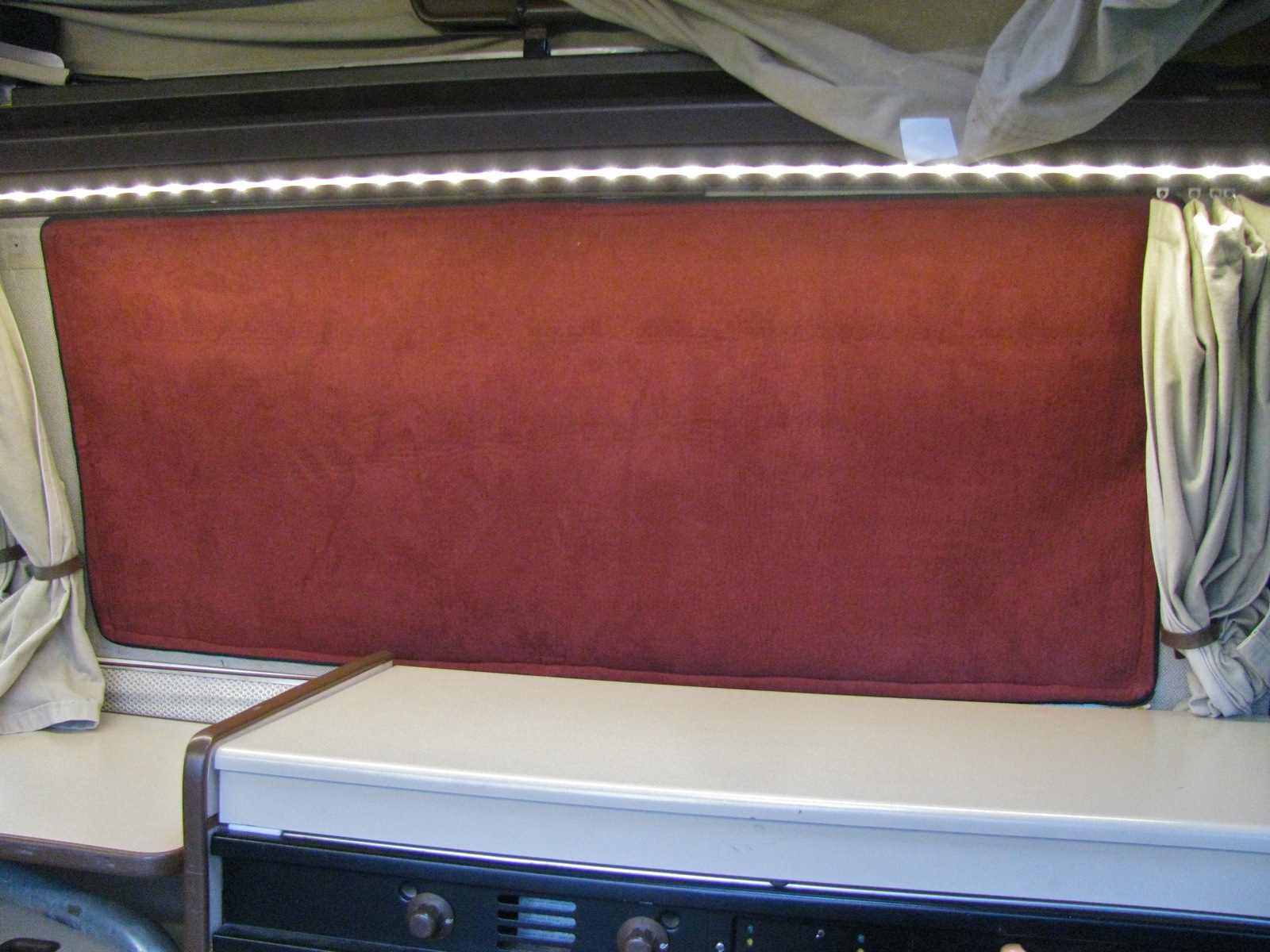
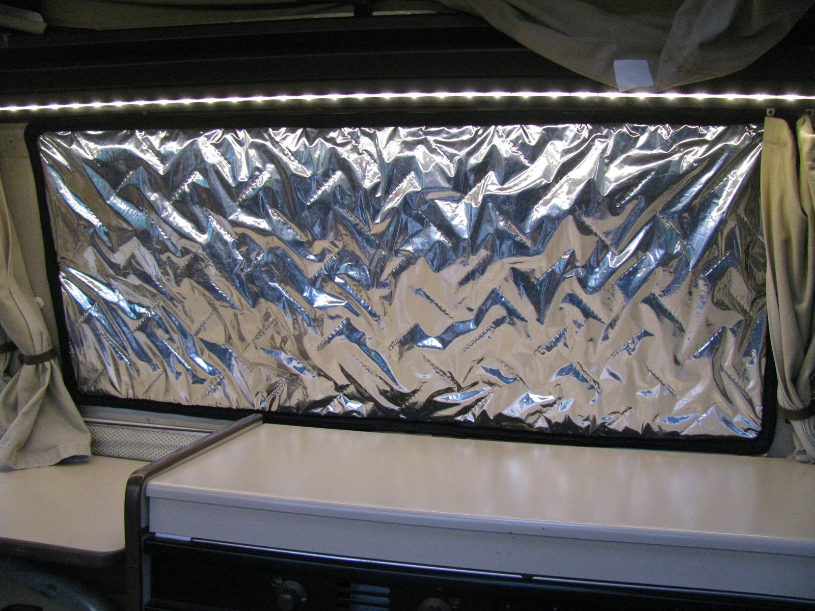
I bought some material a week of so ago with the idea to try making an insulated window blanket. At the fabric store I found some brownish-red microsuede material that was deeply discounted, and some “Insulbrite” sorry, “insulshine”. foil faced polyester batting material (about 1/8″ thick). I also bought some 1/2″ diameter, 1/10″ thick rare earth magnets. Today my wife sewed things up (and very nicely too) and I think it works out well.
The idea was to be able to have the shiny side in for winter camping – keep the heat in, and the shiny side out for summer camping – keep the solar gain down. I had thought about using snaps to fix the blanket in place but magnets seemed more versatile. I think it turned out well.


I’ll post a bit more on the construction later.
Vanagon – led lighting the glove compartment
Posted by albell in vanagon, vanagon mods on February 24, 2013
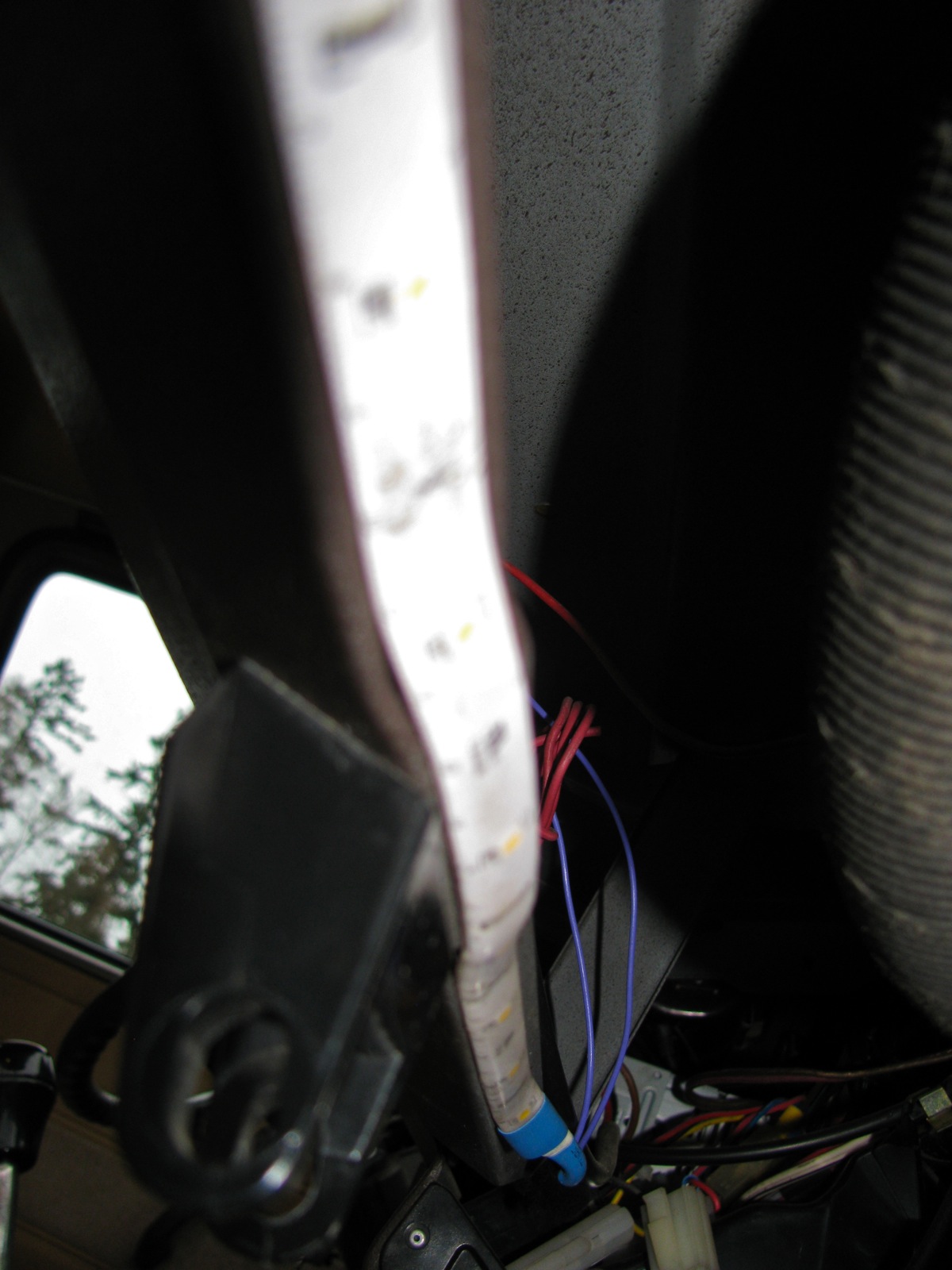
I was in an unsettled mood today, my plans to help good friend Simon add some shims to his syncro were scuttled by unforeseen events. Spent some time with my falling apart dash cluster, trying out a new UV led, but that made me feel worse – the cluster foil is in such bad state that I fear the next time I go in there I’ll really be forced to do a hardwire. So I looked around for an outlet for my angst and I fell upon the 10″ bit of led strip left over from the interior light install shown in last post (on the kitchen side the 2m strip had to be trimmed to fit).
I had this idea to wire it in parallel with the small light above the glove compartment and placed so it would light up said compartment. And I didn’t want to dick around and fuss with the install, so what follows could have been done better.
Look up the Wikipedia entry for glove compartment. I draw your attention to the last paragraph, more proof that the Vanagon was a car ahead of its time.
Most led strips can be cut on the indicated lines (drawn on face of strip), at the cut area there are soldering points. I soldered a couple of wires to those points (nice tinned, teflon insulated wires).

Then some heat shrink.

Polarity is important, that’s why I have both wires the same colour . There are tiny +/- markings on strip, but you can confirm with 12 V power source (I’m fortunate to have an adjustable DC power supply. It is very handy for this sort of dicking around). The positive wire was soldered to the long contact strip on the little light that mounts above glove compartment (what the heck is that light called anyway – Courtesy light? Vanity light? it’s a Map light according to BenT). The negative wire was soldered to the other contact strip. Yes, soldered to the strips. As I said, I wasn’t feeling like doing it kosher.

The strip and wires were fed through the light opening and the light popped in after. The strip has self adhesive backing, and I stuck the strip up under here (sorry about focus).
And how does it work? Some daylight pics to show.
Light off.

Light on.
Well what did you expect? Fireworks?
🙂
Just to be clear, the led strip is now switched on and off via the “courtesy light” or whatever you call that little light above the glove compartment. (BenT: It’s a map light, you dolt)
Vanagon – interior lighting with led
Posted by albell in vanagon, vanagon mods on February 23, 2013
I’ve been wanting to have some led strip lighting in the van for a while but never got around to ordering any online. But a few weeks ago I found some led strips at local hardware store and even being on sale they were pricey ($43 each), but I fell for them. You can do much better price-wise online.
The strips are 2 m long each, with 60 smd leds per strip. That’s a good led density for this application. Calling leds “warm white” is so subjective, a little better descriptor is colour temperature, and these were listed as 3500 K correction, 3000 K. The strips came with a small inline transformer to change 110V AC to 12 V DC. We don’t need that for the van, but we do need some sort of switch. I decided on an inline dimmer/controller from Superbrightleds.com, this one. I ordered 2, one for each strip. When they arrived I realized that perhaps an inline dimmer is not the best way to go, would be better to have a wall mount. Time for some metal butchery. The same old thing with me, going the long way around.
A bit of 1/2″ aluminum.
I really just eyeballed the milling (used the wee milling head for my lathe).
Then a half hearted clean up. I need to get a better countersinks, see the chatter marks in the holes, especially the mounting screws?

And the dimmers added.
The milled slots use now clear. Can I draw your attention to the black heatshrink on the ends of 2 pairs of wires? I forgot to remove one of them, grr.
I secured the wires to some extent with some Goop. The heat shrink job was redone a couple of times after this, you’ll find out why.

And installed on top front inside corner of the wardrobe. I figured I could reach the dimmers when lying in the lower bunk.
The leds strips were installed in two places: one on the underside of the kitchen trough so that it pointed straight down. The other on the angles face of the slider door valence. The latter shines in and down. So I wired the strips to the dimmer and during the process forgot about one of the heat shrunk wire ends, and I shorted one dimmer which let out a little magic smoke. Stupid mistake eh? I left the broken dimmer in place and re-rewired things so that the remaining dimmer controlled both strips. Troubleshooting this screw up resulted in re-doing a lot of connections, sigh.
This pic makes the slider door side strip seem brighter and more glaring than it actually is.
The kitchen side strip has no real glare, I’m guessing the beam angle of the leds is about 120 degrees.

I’m very happy with the amount and quality of the light these strips make. I’d like to add more, and maybe even some RGB strips and a colour mixer.
Addendum : I forgot to mention how much power the lights draw – if I recall correctly it is around 4.8 W per strip. I know nothing of how PMW controllers work, ie how much power is used by controller and strip when light is dimmed down low.
Another addendum:
I did some measurements with my installed Doc Wattson. Measuring current flowing from my aux battery.
first, van as is:
leds off, 1W, 85mA
leds full on, 9W, 750mA
leds dimmed lowest setting, 1.7W, 140mA
Radio face plate off:
led lights off, <0.1W, <10mA
For interesting comparison, kitchen water level/battery meter panel on, led lights off, between 0.2 and 0.3W, between 20 and 30mA.
So the led dimmer control draws a little power even when off, but it is less than the “switched on” kitchen indicator panel.
So the led strips, both sides combined, only draw 140mA power at lowest brightness. And that low setting is pretty good for a standby/casual use light.
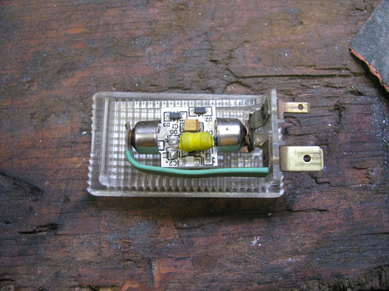
Vanagon – dash/glove compartment light minor mod
Posted by albell in vanagon, vanagon mods on February 20, 2013
Those of you that have the little light above the glove compartment know how easy it is to ground the hot part of the light against the dashboard metal when you remove the light. I have lost count of the number of fuses I have lost that way. Oh sure I hear you say, why not disconnect the battery before removing the light? Well, yes, of course.
But, you can do something else. Slip a bit of heat shrink tubing over the flat metal inside the light. Shrink it up and your good to go. Here is a pic (I have a LED festoon replacement light in there). The light green is the heat shrink over the metal strip.
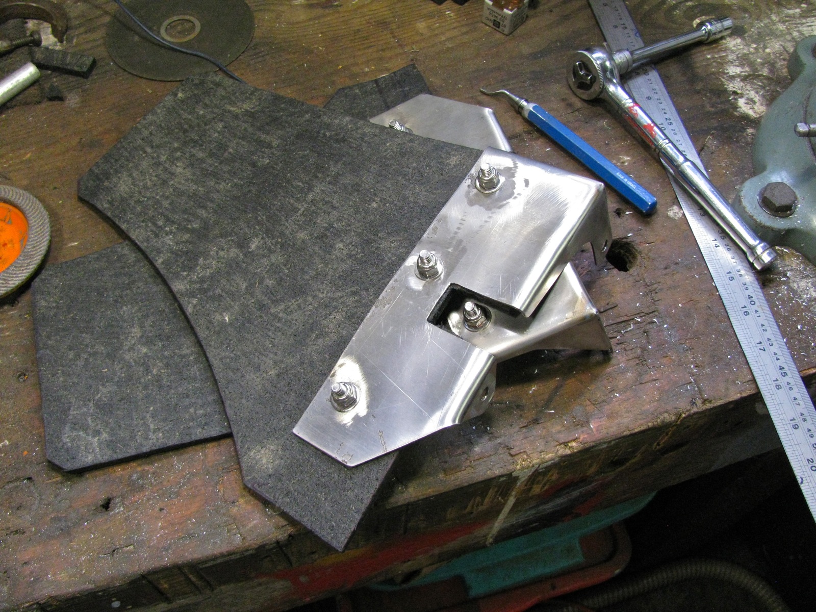
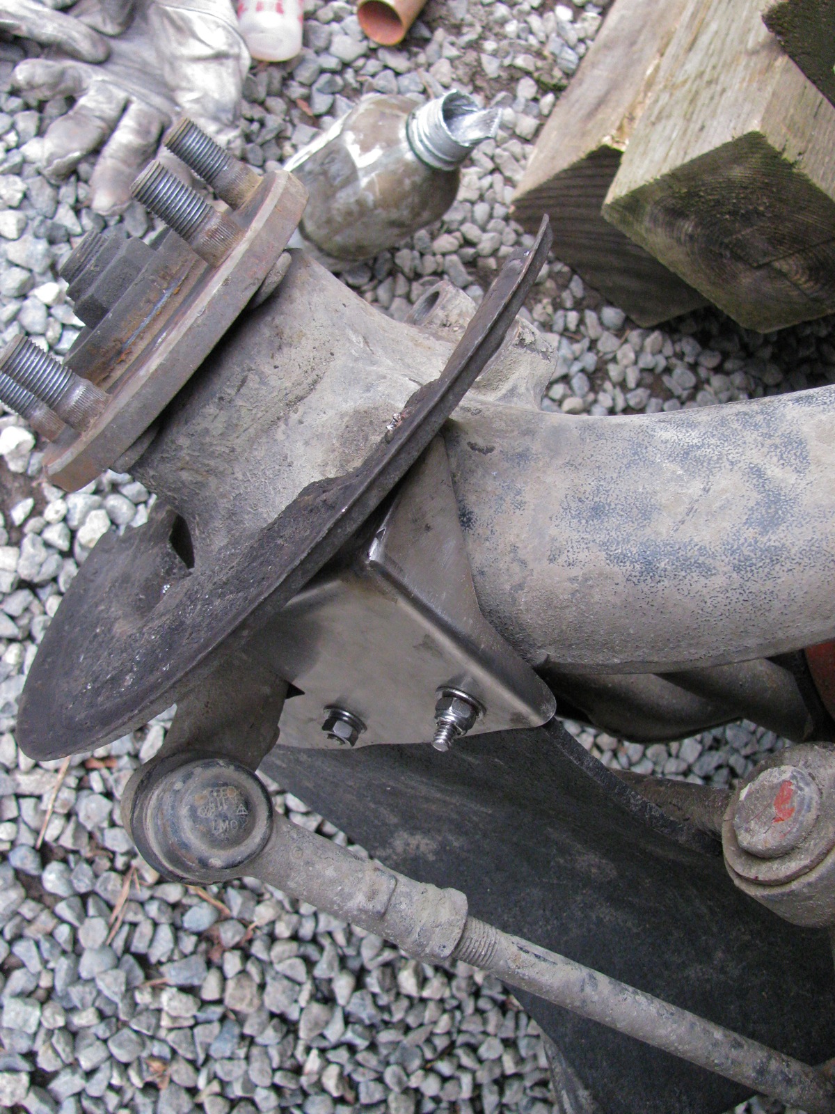
Vanagon – syncro front outer cv joint protection plate
Posted by albell in syncro, vanagon, vanagon mods on February 16, 2013
The story goes that VW introduced these protectors in 1990 for 14″ syncros with the rough road package, and on all 16″ syncros. Here is the English language bulletin.
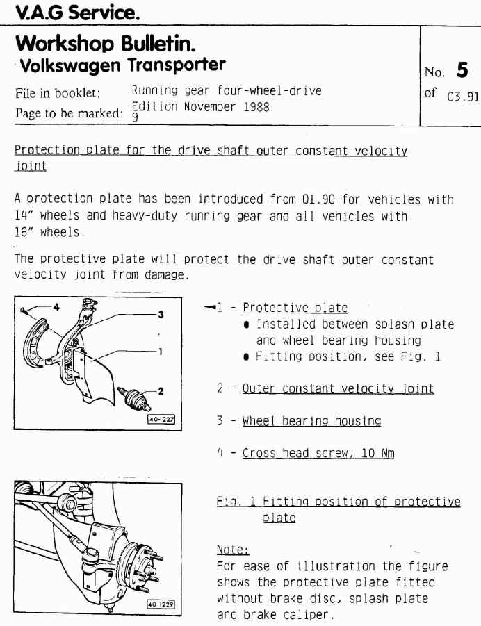
I wanted some. I worry about logging road debris catching on the front outer cv boot, and that boot is a pain to replace. You can buy them, one good source is Burley Motorsports, but seeing as there are plans for them on the internetubes I thought I’s have a go at making a set.
Here are the pdf’s of the plans I used: CV_protectors_bracket, CV_protectors_Rubber. I scrounged all of the material used, so my version differs slightly from the plans. First up are the metal parts. I had some scrap 14 gage stainless which is not quite as thick as speccified ( 1.6 mm vs 2.0 mm), and I glued a print-out of the plans to the metal and cut to shape.
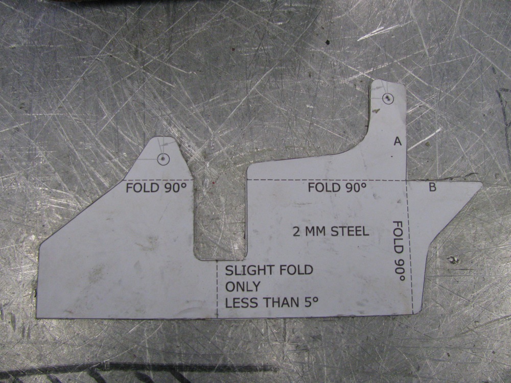
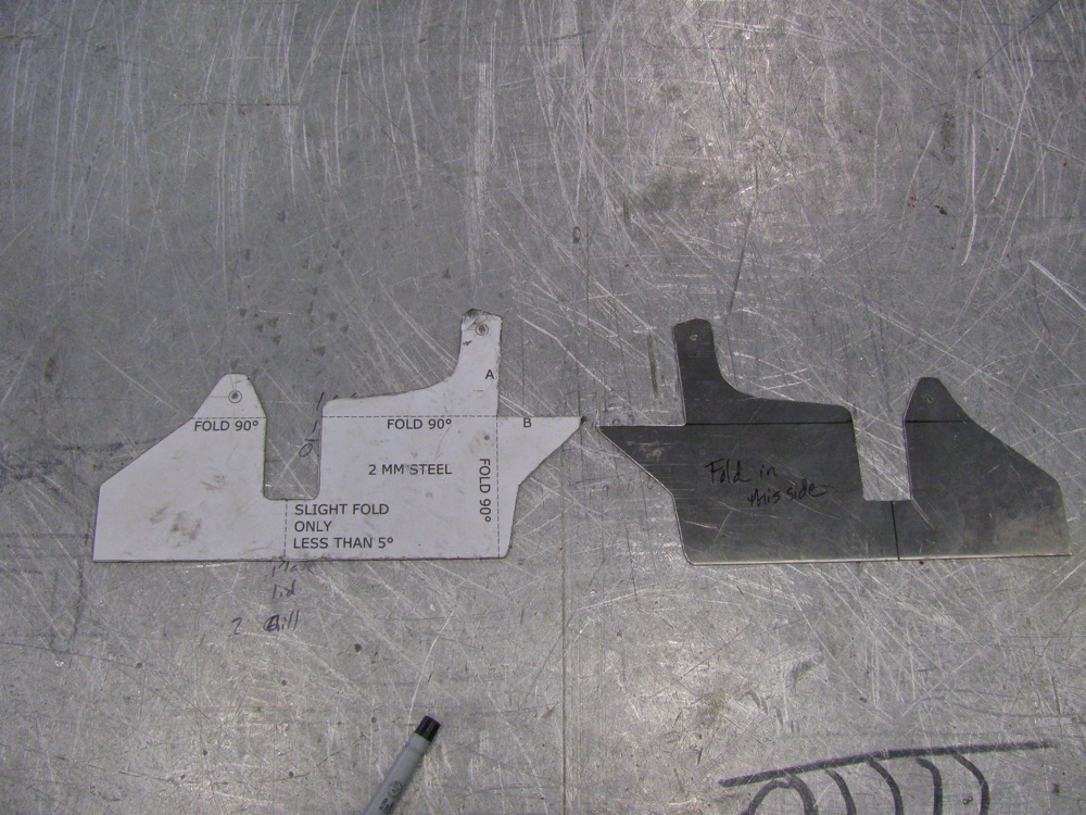
I bent the parts in a vise (that accounts for the less than crisp bends), then I made a hack-job of the tig welding. I need new glasses, well that is my current excuse for my poor welding.
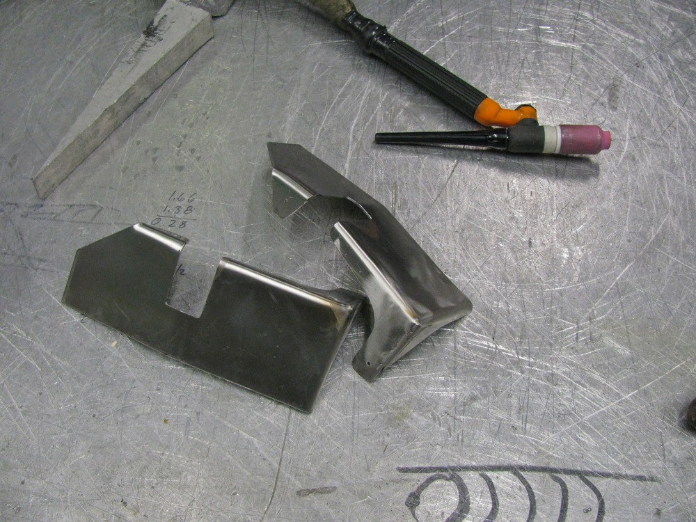
Next was the hunt for rubber. You’d think it would be easy to find some 1/4″ thick, fabric reinforced conveyor belting, wouldn’t you? I spent an hour looking then I used some 1/4″ rubber sheeting that my neighbour had. It is not the best stuff, it is like thin horse stall matting. You know, crumbled tires pressed together. I can always replace the rubber when I find the belting. Ok, enough mumbling, I cut the rubber and I cut some 1/8″ 6061 aluminum for the backing strip. I used 1/4″ – 20 ss carriage bolts (the square part of the bolt shank will dig into a 5/16″ hole drilled in the backing plate) and nylock nuts to hold all the parts together. Well all but one, I ran out of nylocks and had to use a split washer and plain nut.
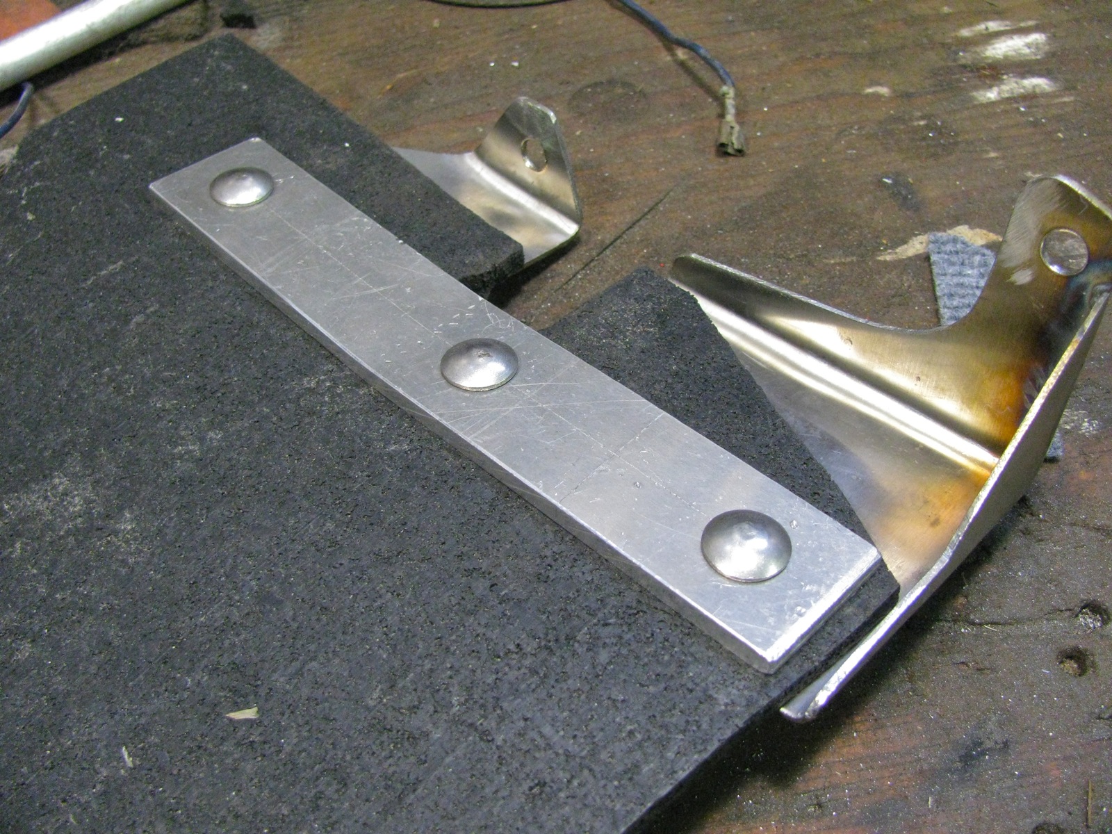
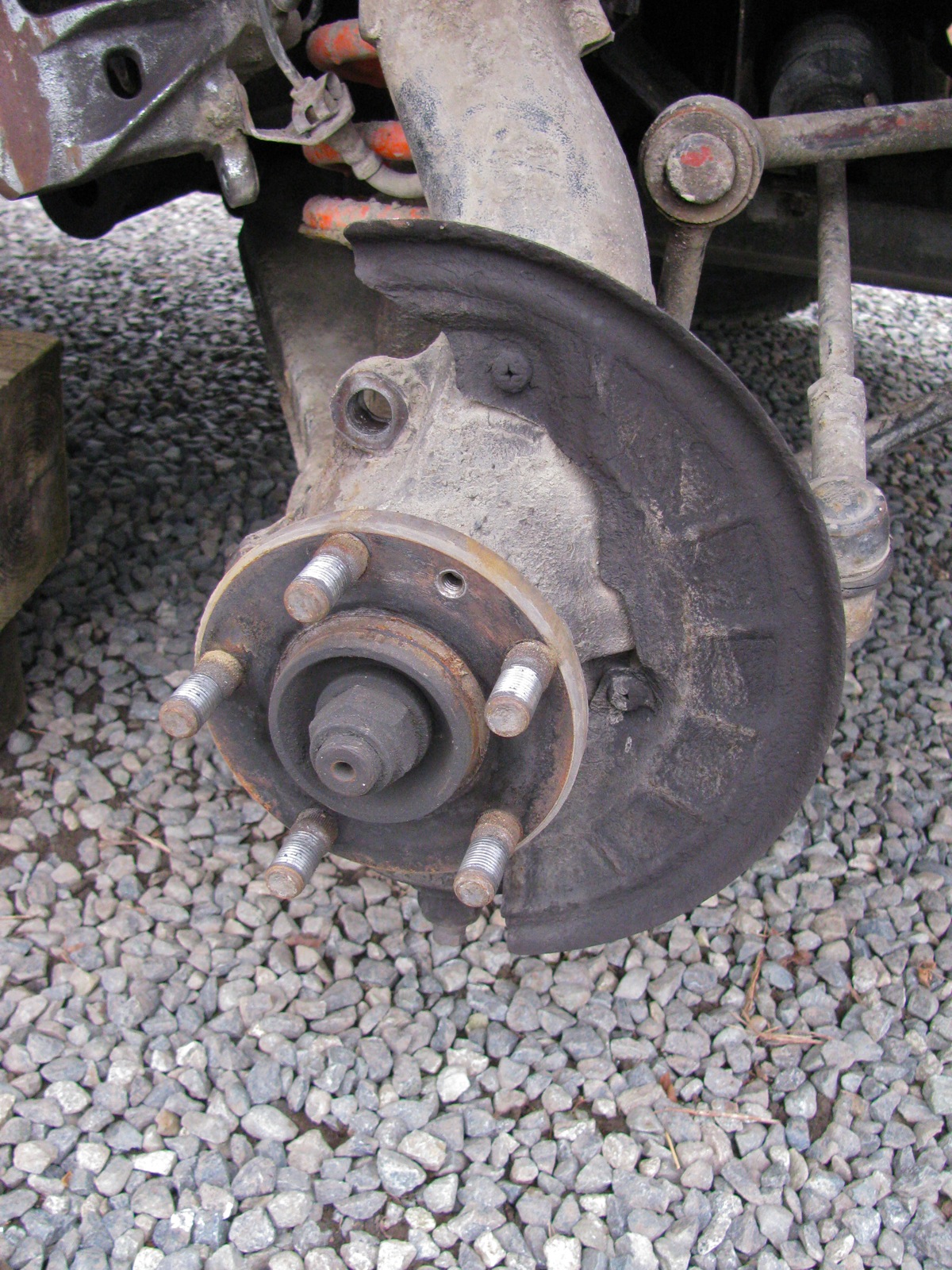
Okee-dokee, out to the van and installation. It is a bit of a pain, you have to remove the brake calipers and rotor to get to the backing plate. The same old but important safety warnings apply – van securely supported etc.
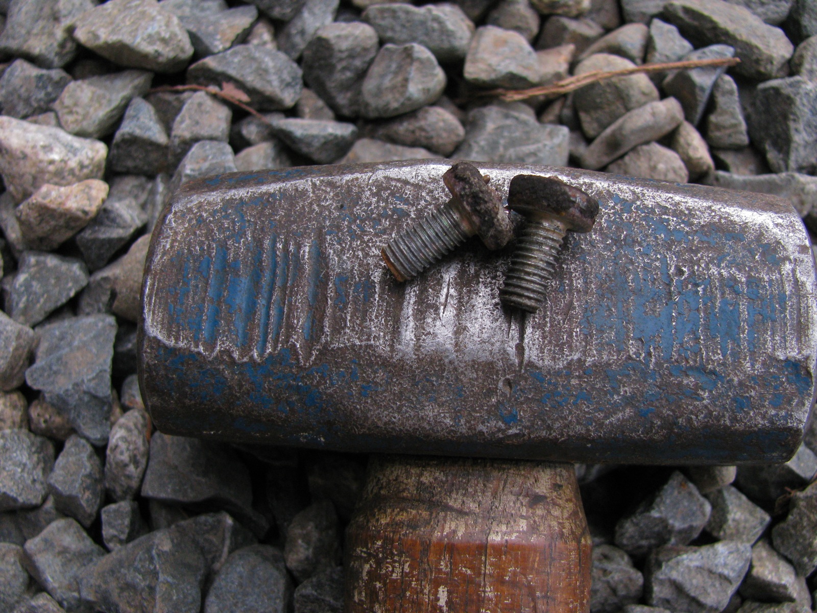
Two phillips headed screws holds the splash to the steering upright (or bearing housing, as VW calls it). They were fekkin tight, I doubt they had ever been removed. I had to use an impact driver, but even so I still managed to bugger up the screw heads a tad. I have said this before about my van, despite the ugly areas of body rust I have, all the fastenings (despite how tight they have been) are not rusted in.
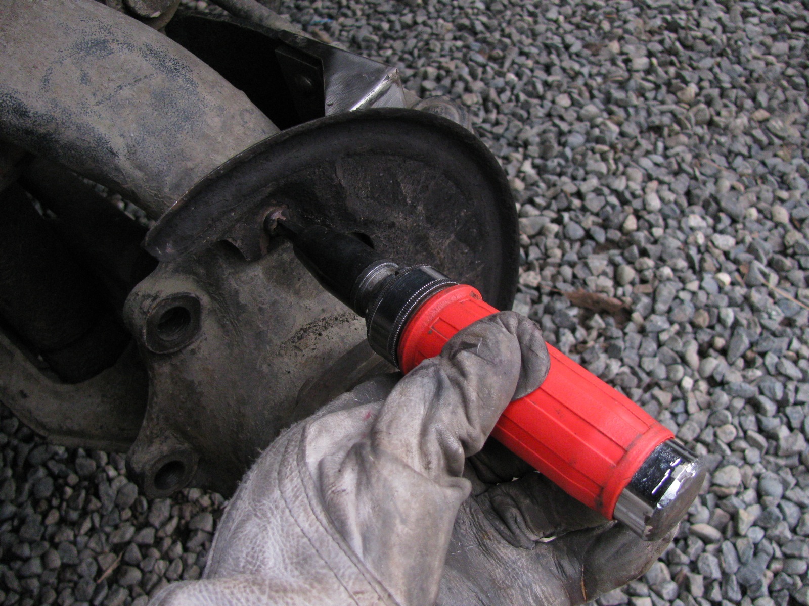
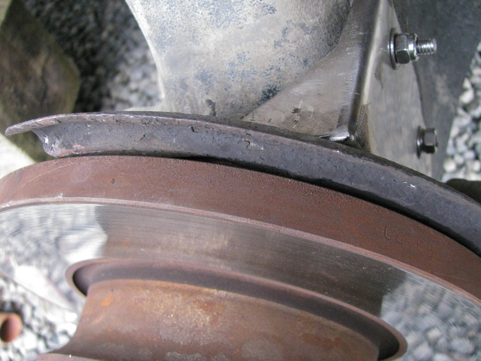
Once the splash plate is off the cv protector goes on and the splash plate reattached.
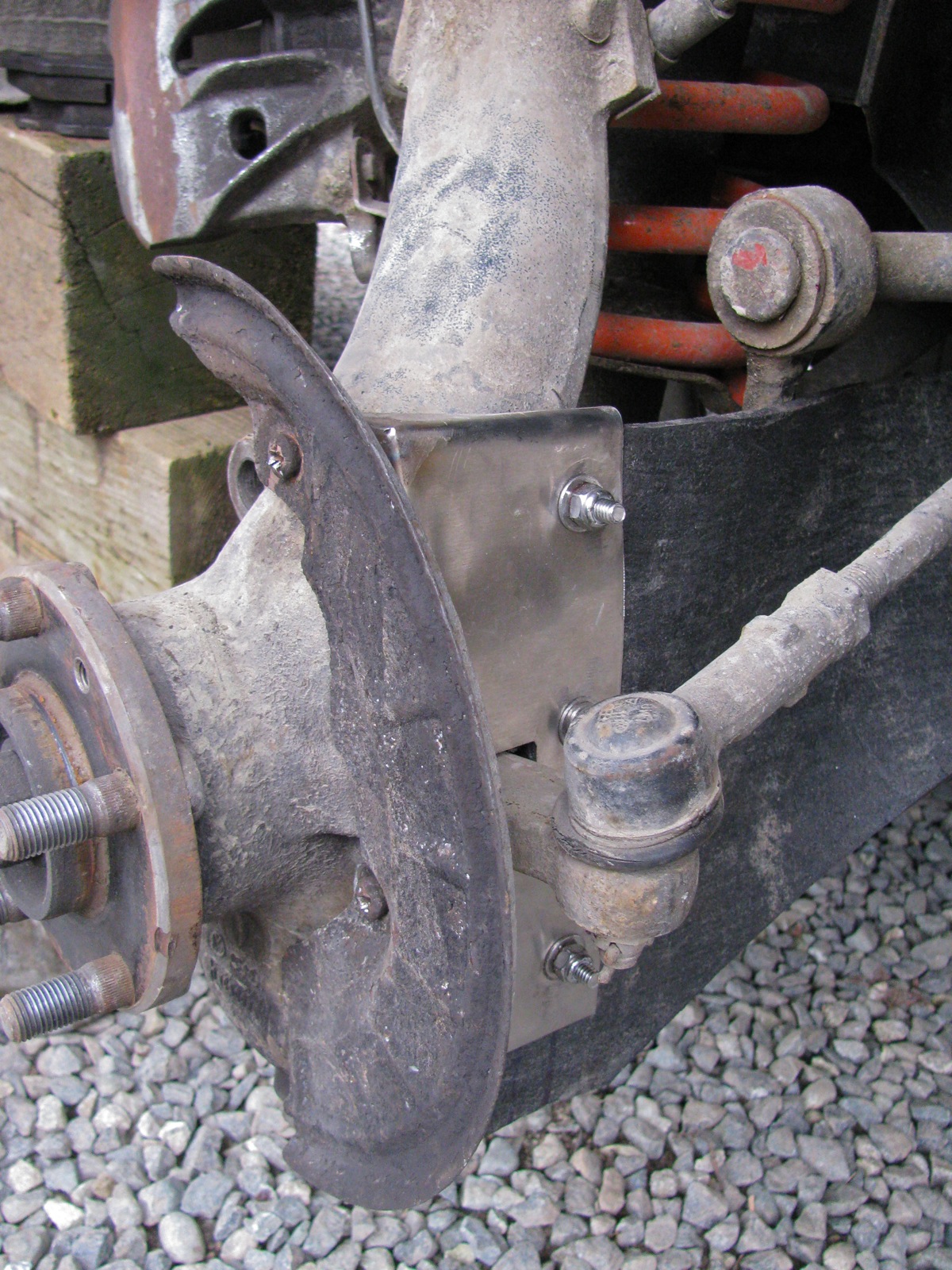
Another view.
Brake rotor back on and the splash plate is now closer to the brake rotor by an amount equal to the thickness of the protection plate, but they do not touch.
The other side went a lot quicker.
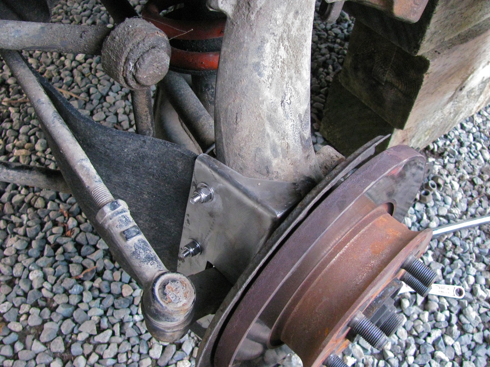
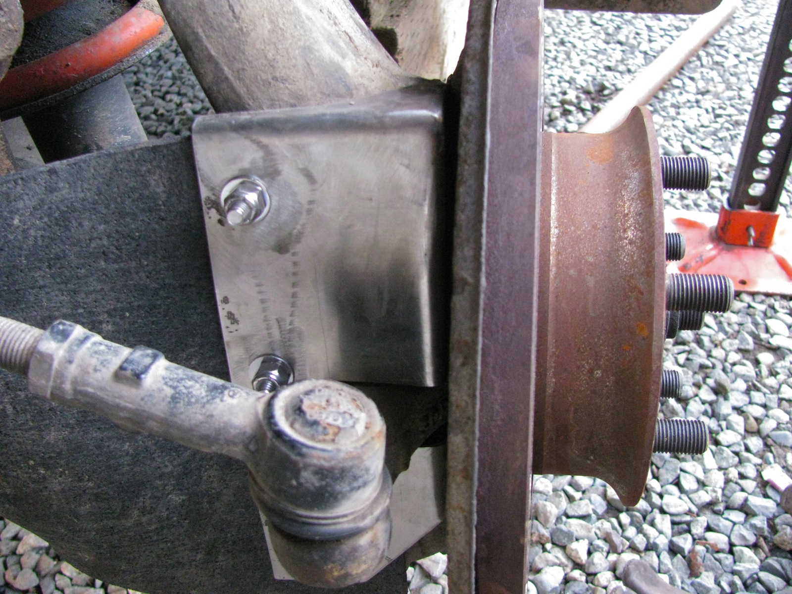
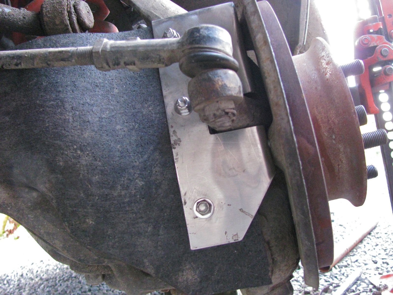
And with the van down on the ground.


I got more satisfaction from this little mod than seems normal. I don’t know why this should be. Perhaps because I do worry about catching a branch up there when I’m on logging roads. Or maybe it is because the project went without any real screw ups.
Addendum/clarifications:
Vanagon – Spillbuster cup/glass holder
Posted by albell in vanagon, vanagon mods on February 10, 2013
Good friend Stephen gave me this for a Xmas present and I got around to installing it. Made in Germany of all places, I didn’t think the Germans encouraged drinking and driving.


I didn’t have the guts to try it with a liquid that would be a pain to clean up, so water it was, in a short trip around the farm.
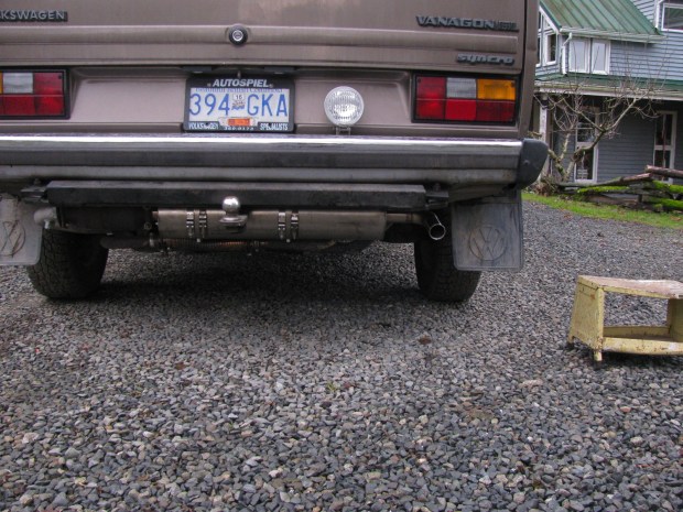
Vanagon – home made muffler installed
Posted by albell in syncro, vanagon, vanagon mods on February 4, 2013
Finally got the muffler installed. Some pics of components are in this post. Since then I made some rough mounting brackets, copy of the stock brackets, but made from aluminum (3/8″ plate) with some 1/2″ studs welded onto the sides (for T-bolt clamps). I didn’t take any pics of the brackets, perhaps I forgot on purpose as my TIG welds were overheated and sloppy (I’m learning, slowly).
Here are the brackets before final shaping, mounted to a spare engine mount.

I copied the stock mounting brackets bolt holes and approximately the curves but adjusted to fit the 6″ diameter muffler. I also copied the relief curve on the bottom side of the brackets, allowance for the transverse connector exhaust pipe. A 90 degree SS elbow and a home made tail pipe was TIG welded on.
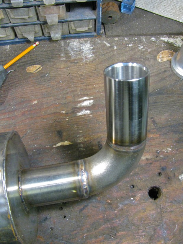
Install was pretty easy, brackets bolted right up to the engine carrier, ok, I admit, I didn’t get the muffler quite level. Once installed I realized I could have made thing a little differently to tuck the muffler up a bit higher. But all in all I’m pleased with how it hangs.

You can make out how the T-bolt clamps hang around the welded studs on the bracket. You might also make out the section of SS flex on the transverse exhaust pipe – a quick and dirty repair after cracking that pipe on a logging road trip.
And I made a little video to give you an idea of the sound. It is not as quiet as a stock muffler, but neither is it loud. Does have a throaty note.
I’ve always wanted (for some obscure reason) to make a muffler. And now I have, and by gum it worked. It’s the little things that get me through the day 🙂
Vanagon syncro – front spring swap and radius arm bushing replacement
Posted by albell in syncro specific repairs, vanagon, vanagon mods on January 6, 2013
The other thing I did recently was swap in a pair of front springs from my old ’82 westy into the front of my ’86 syncro. You know that that suspension set up is different between the 2wd and syncro vanagons, the syncro has a spring perch on the shock absorber and uses (generally) shorter springs than the 2wd vans. I compared the spring lengths of the ’82 diesel westy and my ’86 syncro in this blog post, and in this post. This particular 2wd spring is about 20 mm longer than the syncro spring, but the wire diameter (approx 16.6 mm) and number of turns (8) are the same. The spring rate, if I have identified the 2wd spring correctly, is according to the IG16 wiki 80 N/mm. It is the same spring rate as the syncro springs I have. It seems only one spring type was installed in North American market syncro tintops and westies.
I’ve not been pleased with the amount of “springing” in the van. With the westy conversion it must be a bit heavier than it was as a tintop, and I find that the van scrapes the spare tire clamshell on the ground when I’m negotiating ditches, trenches etc on logging roads. Friend Simon would add that my excessive bulk is not helping things. The distance between the front fender lip and the wheel centre was about 18.25″. I would like it to be at least 19″, but not more than 19.5″. At the back it is trivial to add some shims to raise things, and I did do that (rear measurement 19″). That shimming made the front end look even lower.
I’m not ready to dive into the hyperbole ridden and expensive world of aftermarket springs and shocks, and one must consider springs and shocks together. Increasing the spring rate does require increasing the dampening abilities of the shock.
Originally thought that I would add a shim to the top of the spring, but then I decided to give the spring swap a go. I did not know whether the “no compressor spring removal” technique would work with longer springs so I bought a rather cheap spring compressor from Princess Auto. Spring compressors give me the willies, I feel like I am on a bomb disposal mission when I use them.
Upper A-arm disconnected from upper ball joint, you’d think there is enough room to get the compressors in.

Nope, not enough compression with this set up.

Ditto here. The hex area at top of compressor does not allow you to get a grab on a higher coil, plus at the other end, the screws are too long and interfere with the axle shaft. I wasted about an hour mucking around with the compressors, I finally gave up. I could have cut the screws down, but I was of two minds about that. Was it worth wasting more time trying to get them to work or try and return them to the store?

So I went back to the no compressor method. Radius arm arm was removed, sway bar drop link disconnected, nut and rubber bushing removed from top of shock, and the lower control arm carefully lowered so that the spring and shock could be pulled out to the side and the spring removed. One thing though, I had installed a westy swivel seat base on the passenger side this summer. So I had to make a hole in the base to access the plug that, once removed, allows you to put insert a tool to guide the shock back up into the shock tower during re-install.

So, I got the passenger side spring installed (radius arm bushings on that side done too) on New Year’s day. With one spring installed, and before driving to settle things in, I got a 19.5″ measurement from hub centre to fender lip. I like that look, it is as high as I want to, or should go. A couple of days later I got the other side done and the hub to fender height settled in at 19 1/8″. Driving the van felt a little different, I could tell the front was higher (yes, I really could detect the change), there was no difference in how the van dipped or raised over bumps. Mind you this was only driving over the lumpy roads in North Saanich, no logging road travel done yet.

Now some shameful pics of the dreadful state of my radius arm bushings…
New bushings and radius arm. Note the shiny spacer I made over a year ago.

Old and new.

“By Timothy, what a difference”

“Shocking!”

Conclusions?
Well I think the spring swap was worth the effort but I will add a teeny tiny little spacer (about 1/4″ thick) to bring it up to 19.5″ hub to fender lip measurement. As to the radius arm bushings, I don’t think any further comments are needed.
Vanagon – my auxiliary battery wiring
Posted by albell in syncro, vanagon, vanagon mods on January 6, 2013
I only had a little time to do any Vanagon stuff over the break, a couple of things were dealt with, I’ll post it up over the next couple of days.
First up is my auxiliary battery install. It has been working fine for the last couple of years, but recently I have noticed (with the help of the Doc Wattson, blog post here) a couple of disturbing things. First one is, and I have not figured this out, is a peak amp reading of 20 – 30 Amps. I never see it happening, even with mucking around with stereo settings while I look at meter. And I don’t have a circuit in my aux. battery set up with a fuse larger than 20 A. I do suspect the stereo amplifier, but it must be a very brief transient spike in current draw.
The second thing is a chronically undercharged aux battery. I suspected, and suspicions confirmed by the Doc Wattson, that the Blue Seas ACR (a now discontinued model, CL series BatteryLink, p/n 7600) I use to switch between the main/starting battery and the aux battery was not combining the batteries when it should have been. The ACR ( automatic charging relay) does have indicator lights on it, but the unit lives under the driver’s seat.
The ACR has provision for wiring in a remote located LED that lights up when the ACR combines both batteries. So I set about adding that and at the same time I would go over connections and ACR settings. I suppose a picture to give you the lay of the land would be a good idea. I admit, it is a bit of a dog’s breakfast. Working around clockwise the stereo amp is on upper left (old Alphasonik that came with van), then auxiliary fuse panel, to the right and up is the Doc Wattson meter, below that is the 31 A/hr AGM auxiliary battery, Schumacher trickle charger, then finally the Blue Seas ACR.

Yeah, clear as mud. Fine then, I’ll make a quick sketch.

Edit: link to how I connected to main fuse panel S3 circuit from aux. fuse panel.
Under the cover of the auxiliary fuse panel. Its is from an early 2000’s Golf/New Beetle and was installed right by the battery. Useful little thing, I’ve had this one for about 11 years (used it on my old ’82 westy).

Ok, back to the ACR trouble shooting. I ran a pair of wires up to the dash, and mounted a blue LED indicator light in a rather temporary way under the lip of the dash. The light is from Princess Auto, made to fit a 1/2″ hole and has resistor built in, much easier to buy than to fiddle around making one up – ha, I must be getting old. Disregard switch and knob to the left of the light, has nothing to do with this job.

Testing connections, oh, brighter than I imagined. Looks like it is going to provide some mood lighting.

Ok, so I have the indicator light installed which will let me know when the ACR has combined the starting and the auxiliary batteries, and I have gone over wiring connections and ACR settings. First time I drove the van all went well, the LED came on after about a minute (this is as it should). The second time I drove the van the light did not come on, the ACR did not combine the batteries. What is going on? I moved the driver’s seat and looked at the ACR – well blow me down – the over voltage light was on.
I should explain, the ACR has 2 user adjustable settings. One is the voltage at which the batteries combine or un-combine. I have it set at 12.5 V and that means when the ACR senses that the voltage on the main (starting) battery drops below 12.5 V it will un-combine the batteries. And when the voltage measured on the main battery is above 12.5 V, than the batteries are combined (there is a time delay built in to weed out voltage spikes).
The second user adjustable parameter is the over voltage setting. The manual states:
“The OVERVOLTAGE potentiometer is used to adjust the voltage at which the CL-Series BatteryLinkTM ACR switch opens in response to high voltage. This is a protection feature when one battery needs to be charged at a lower voltage than the other. It also protects the second battery bank in the event of an overvoltage condition produced by the alternator.”
The van is still running and I glance over at the Doc Wattson meter and notice that it reads 14.94 V. So that’s it, the ACR has un-combined the batteries because of a too-high alternator voltage. I had the over voltage set to 14.85 V, and that seemed fine as I had adjusted my alternator to 14.5 V (yes, I have an adjustable reg. on the alternator), but now the alternator was putting out 14.94 V. It is strange, I didn’t see that high a voltage any time before.
I re-adjusted the voltage reg back down to 14.5, and the over voltage light went off and the batteries were combined.
Edit: Dennis H. advised me to re-adjust the voltage reg down to a max of 14.2 V. I think I will follow his advice.
So was this the ironic reason my aux battery was being undercharged – alternator voltage too high? I have to admit that I’m not 100% confident in the adjustable volt reg. I put in the alternator. I had one flake out on me on my old ’82, and now this one might be showing signs of “wear”
Finally (thank god, what a long winded and dull post), I still have that old Halon fire extinguisher I had in the ’82.

Vanagon – muffler update
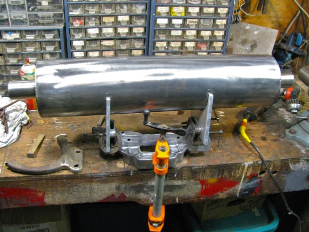
Posted by albell in metal working, metalworking, syncro, vanagon, vanagon mods on December 13, 2012
I got the final end cap welded on today, not the neatest tig weld due to my poor cutting of that end of the can. No filler was used in the weld, just flowing the parent material. I gave the muffler a quick once over with a cup wire brush on the angle grinder. I think this is as far as I am going with the finish, I don’t see myself holding the thing up to the buffing wheel for a couple of hours.
The pics show the muffler sitting on some aluminum off cuts ( I have access to a lot of interesting shapes in various thicknesses of aluminum, remnants from water jet cutting of work parts). These scrap bits had curves to match the radius of the muffler. The scrap is clamped to a spare engine mount casting so I can see how I need to move things and what metal to remove. I’m leaning towards the aluminum supports (yes David, there will be electrolysis where the ss and Al touch:)) with some T-bolt ss straps holding the muffler tight.


Vanagon – making a muffler
Posted by albell in metal working, metalworking, vanagon, vanagon mods on December 4, 2012
As if I don’t have other things to do, I’m making a muffler for the van. I’ve had the idea for years so why not give it a go eh? Scrounged materials used:
– perforated stainless tubing for the straight through internal pipe, 2.25″ diameter, wall thickness about 3/32″
– a section of 6″ diameter stainless tubing for can, again about 3/32″ wall.
– 2″ diameter stainless tubing for in and out pipes, 3/32″ wall.
– some stainless sheet for end caps, a hair under 3/32″ thick this time.
– stainless swarf from some big ass lathe for internal packing.
I made a start yesterday, got good buddy Dave to do the TIG work, hope to have it finished in the next couple of days.


Vanagon – Doc Wattson install – initial thoughts
Posted by albell in vanagon, vanagon mods on November 20, 2012
I installed a Doc Wattson into the house battery circuit of my van last weekend. I must emphasize that I have very light electrical demands when camping. Interior lights are LEDs, one fluorescent light under the trough, the fresh water pump, kitchen unit indicator lights, and the stereo and cig. lighter is the total draw on my 31 Ahr AGM aux. battery. The Doc Wattson acts as a (only one way unfortunately) power meter showing and recording battery voltage, battery lowest voltage, current draw, peak current draw, watts used, and kWh. The connections made are all via short pigtails of 14 g, fine stranded and silicone insulated wires. This small wire would be a concern if the unit was used to measure larger currents (say above 20 A). The black wires on the unit carries the current, and in my install they connected the neg battery post of aux. battery to chassis ground. Any one of the 2 red wires is connected to the positive terminal of the battery. Keeping the wire runs as short as possible the meter ended up just in front of the front table support bracket.
That was a very brief outline of the install, more info from the source here. So what did I find out about things electrical these past couple of days? Well I took some pics to show. I reset the gauge before these pics, so kWh and Ahr will be showing zero.
Here we are, engine off, stereo has been on but now off, stereo head unit still attached. 80 mA draw eh? That drops to zero when face plate off (or as close to reading zero as the meter resolution allows) BTW, I noticed the kitchen panel indicator draws somewhere between 10 and 20 mA when switched on.

Stereo on and playing (have external amp too), volume at camping level. See the peak Amp (Ap) reading?

Engine on, both the house and starting batteries have been combined via my Blue Sea System ACR. I have an adjustable voltage reg. on my alternator and it is adjusted a tad high I think. When the 2 batteries are combined the ammeter portion of the meter does not work (the starting batter neg to chassis connection by-passes the meter). But once the ACR separates the batteries when the ign key is off then the stored current and power values are displayed.

So what do I think? Some pros and cons:
Pros – inexpensive, easy to install, handy at a glance indication of how much electrical power you are using.
Cons – measures current via neg ground path. That means, in a car with the chassis as return path, you can’t (as far as I can tell) measure a particular circuit. One way measurement – would be neat if when the engine is running and the battery was being charged, the meter would run backwards and show the elimination of the electrical debt you got into. No back light.
I’ve got more to say about this meter, and would like to show the install wiring. But I need to get my wiring runs neater before then.
Vanagon – main battery kill switch
Posted by albell in vanagon, vanagon mods on August 24, 2012
There have been a couple of disturbing posts recently on the Samba and on the Yahoo Syncro mailing list about Vanagons moving on their own and or catching fire due to massive electrical faults. A short somewhere in the ignition wiring causing the starter to engage etc. It’s enough to make even the most happy go lucky owner shiver. A recent post to the Yahoo Syncro group mentioned this kill switch – Amazon link and how it was possible to mount it on the negative pole of battery (starting battery under front passenger seat of gasoline Vanagon). I happened to be out Langford way today and dropped in to Princess Auto and found what looks like the exact same switch ($9.95).
It is a squeeze to get it on the negative post of the battery (I installed the Westy swivel seat base on that side, that does not help matters at all), and the taper on the switch is designed, I think, for the positive post so you have to be sure to tap the switch down to the base of the post.
It works as advertised, a turn of the green knob connects/disconnects the ground. I have a house battery under the driver’s seat (and a fused distribution box) that supplies power to the circuits needed during camping i.e fuse #3 circuit (which powers radio, interior lights, cig. lighter, clock) and power to the kitchen. The kill switch will be used when van is parked for a time, or if I feel especially paranoid. The battery compartment lid does fit over it ok.


Vanagon – sliding door quietening hack
Posted by albell in vanagon, vanagon mods on August 23, 2012
As seen here on this Samba thread and I got the tape from Lee Valley, (link to product page). I’ll cut to the chase and answer the question “Is it worth it?” – yes. It really does make a difference in the noise made by the sliding door as it is opened and closed. This is on my ’86 syncro which has the improved sliding door set up that started in ’85. That improvement in door design is one of the nicest mods VW made to the van over the years. Ok, on to the hack.
First I pulled the track cover off the side of the van. Two screws at either end of the cover and then some wrestling to get it off. I’m not going to tell you the exact motions needed to get the cover off, but for goodness sake’s don’t pull the bottom of the cover out towards you. That is not the way it goes. It comes off straight up but you do need to clear the tabs that the attachment screws use and that does mean you have to ease the cover out a little towards you then back to the van. Sometimes grime and crap glues the cover to the van, so be careful.
Cover off and this pic shows the track one of the rollers rides on. You have to clean and degrease. And this is when I realized that I would only be doing a half assed job. You see the paint is worn off the track, and when I stick on the tape there will be no grease to keep that track from rusting. The best thing to do would be to paint on some POR15 or something similar before sticking the tape on. But I have a really annoying summer head cold right now and I just didn’t have the energy.

The forward end of the track. Two rollers there, and four surfaces to be covered in tape.

The lower track covered in tape. The tape is folded over the top edge of the track. It stuck on pretty tight. Both vertical inner surfaces of the track above this one was covered too.

I did this mod to my old ’82 years ago – a bit of self adhesive bitumen impregnated fabric to try and stop the track cover from acting as a sound board.

I put the cover back on and tried the door. Much better, really, I’m not joking. But still not as quiet as I thought it should be. I could hear noise from the upper track above the door opening. A roller bearing here as well, not the old plastic block of the pre ’85 doors. Tape applied to the outboard vertical surface (the only surface that showed sign of wear).

And I cleaned up the lower track surface, the one at the foot of the door. The track that is often dirty and greasy and rusty. Now I have my share of rust on the van, but fortunately the track surface was good and it got the tape. And now some proof. Note that the last clip that is titled “tape added to upper track” , the lower track had been taped too. God I have to deal with the rust on that door.
Vanagon – my inattention one year ago bites me
Posted by albell in vanagon, vanagon mods on August 7, 2012
So I notice the seal on my luggage rack was detaching from front rack, damn 3M weatherstrip adhesive failed me (see here for glue on pics). So I pulled off the luggage rack to re-glue the seal and I was shocked, shocked I say, to find some rust spots on the roof under the seal. Pic below is after I scuffed with Scotchbrite pad.

Was it just abrasion by the seal on the metal roof? No, looking at the seal I could see bits of rusty metal embedded in the rubber. Bloody hell, looks like metal filings trapped between the rubber and the roof. A lot of filings were created when I was cutting up the roof to add the pop top, and I thought I had cleaned them all up before installing the luggage rack. I’m sure I did, perhaps some fell through the drain holes in rack and lodged themselves under the seal. In any event, it was my fault .

I masked off and painted some POR15 over the affected parts. I scrubbed the embedded rusty bits from the seal and re-glued it back on the rack, this time using clear silicone caulk.

While I had the rack off, I glued on some stainless mesh on the underside of the (5) drain holes. Some have used little stainless filters that you find on some garden hose connections, but as I had the stainless mesh… I used “Automotive Goop” to glue the mesh onto the fiberglass and that glue worked very well.

But that rust, what a pain.
Vanagon – roof rack mounts
Posted by albell in syncro, vanagon, vanagon mods on August 5, 2012
A bit of a kludge, but I wanted to get some racks up on the van to carry my son’s kayaks and perhaps a Thule roof box. My old towers that I used when the van was a tin top would have been pretty tall on artificial rain gutters mounted to the pop top. We had another Thule rack, used on my wife’s Subaru and is one of those “sits on the roof and clamps to door frame” types. I decided to use it but swapping in the longer bars from the tall tower set.
Ok, to the scrap bin for this bent bit of 1/8″ stainless and away I went with the angle grinders.

I must have been hepped up on goofballs, this was the result for the rear most bracket (to be attached via pop top hinge bolts)

I drilled them for mounting and put them on. They looked, in a word, ass. Ok, back to the pile o’ metal and out with some 3/16″ (!) stainless flat. Cut, drill, grind, etc. and got something a little better. The first attempts were cut down to make the forward mounts and here are the results.


The racks are pretty firm, even with the forward pads not 100% in contact with roof.
Vanagon – syncro front spring pad
Posted by albell in syncro, vanagon, vanagon mods on July 17, 2012
I think I mentioned in my post about upper control arm bushings that I was considering further tomfoolery with the front suspension. What I have in mind is a modest front ride height increase – 1″ at the most – to compensate for the weight that the camperisation added to the original tin top. Currently I have approx. 19″ from wheel centre to fender edge on the rear (one extra stock spacer above rear spring) and 18″ from wheel centre to fender at the front. You probably know all the approaches to ride height adjustment, and no doubt have your preferences. I’m going to have a go making some spring pad spacers, similar (but not identical to) what Futbus in the UK sells.
I discovered that the spring pad is the same for both 2WD and syncro, so I could make a spacer to fit the 2WD stuff I have on hand. Here is the spring pad, underside that fits onto end of spring. Yup, that orange paint is there again. BTW, the spring (from ’82 westy diesel) had 2 white paint marks in middle of coils. The closest match I have found is the 2 beige mark one listed on the IG16 Wiki page about springs here. Do you get the idea that I am tempted to try these spring out on my syncro despite the 20 mm or so longer length? I am, but I want to have springs side by side on bench to confirm length differences. IG16 chart says it’s 20 mm diff, and that would translate to a 33 mm ride height increase (all things equal, ie spring rate). That is a tad more than I am shooting for, but so close as to worth trying.
Oh BTW, “x” amount of lift at spring translates to approx. 1.66 “x” at wheel. Slightly different multiplier at rear. The IG16 Wiki explains more.

You can see how the spring fits into spacer and the remnants of the tape that holds spring to spacer during installation.

So back to the additional spacer idea. I had this doughnut shaped bit of aluminium, was going to make some other goofy thing out of it, but never did.

I wish it was thicker stock so that I could have had a longer collar.

As is, I made the spacer 16.75 mm thick, and the collar 8 mm. The stock was originally nominal 1″ thick. I made a little bit of an effort to radius the top corner to mimic the stock rubber pad.


And the rubber pad pushed onto the collar of the aluminium spacer. This pic could be a little confusing, there is an aluminium disc under the spacer, more salvaged scrap.

Whoa! There’s that orange spring.

Pad and spacer on spring.

I probably will use some adhesive between the pad and the spacer. Seeing as I am just trying to bring ride height back close to stock tin top specs, I don’t think I will need to extend the shock shaft at threaded end. More on this to come later.
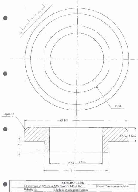
Addendum may 2017
Here is drawing I found in my files for Beau, pretty close to my estimates I mentioned in comments. Thickeness can be altered to suit of course. Don’t forget the multiplier effect of shim to effective lift.