Archive for category vanagon mods
Vanagon – USB outlet, voltmeter, custom vent
Posted by albell in vanagon, vanagon mods on April 17, 2016
Bought one of those ubiquitous voltmeter and USB combos from bangood.com. Thought I would modify the vent on the fridge cabinet to install. But the old grill on the rear face of the cabinet had peeling paint and I didn’t like how the install looked. So I made a new grill from some 3/32″ thick aluminum plate. I milled slots, 3/8″ wide, on 1/2″ centres, 7 slots in total. And I milled a hole for the voltmeter/outlet combo.
The grill turned out a bit “gappy”, a bit too open perhaps. But as you don’t really look at it face on too often it’s good enough. The outlet and meter are wired to my auxiliary fuse panel under the driver’s seat. I thought about a switch to turn the thing off when not needed but I didn’t have a switch that would suit. I might add one later, but right now my big assed house battery will take any parasitic drain.
I’ll replace the mounting screws with the ones that will accept a plastic cap when I can find some.

Vanagon – Nathan meets very nice syncro tin top
Posted by albell in syncro, vanagon, vanagon mods on April 16, 2016
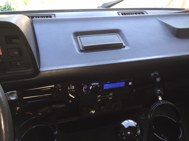
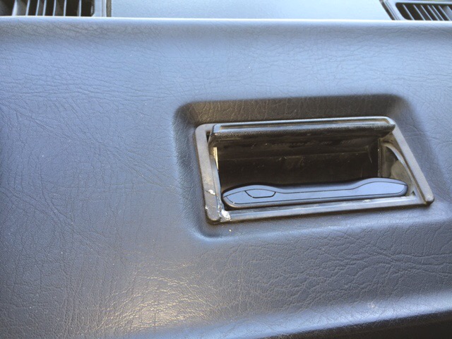
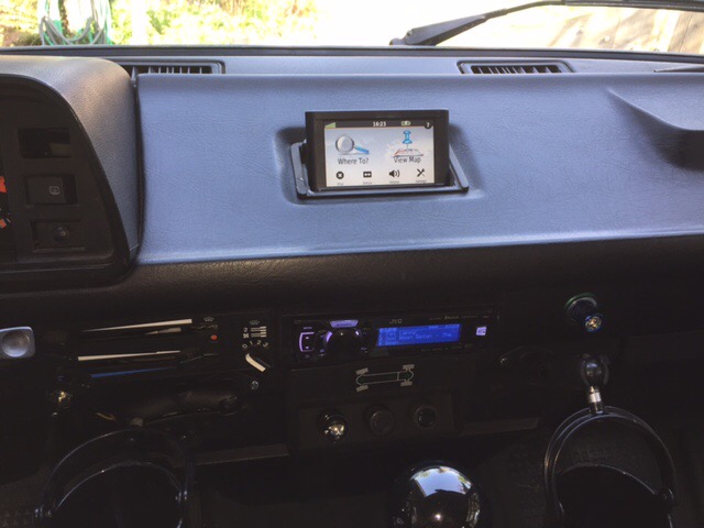
Addendum April 16, 2016. Very nice install of Garmin Nuvi 44LM in ashtray, pics at bottom.
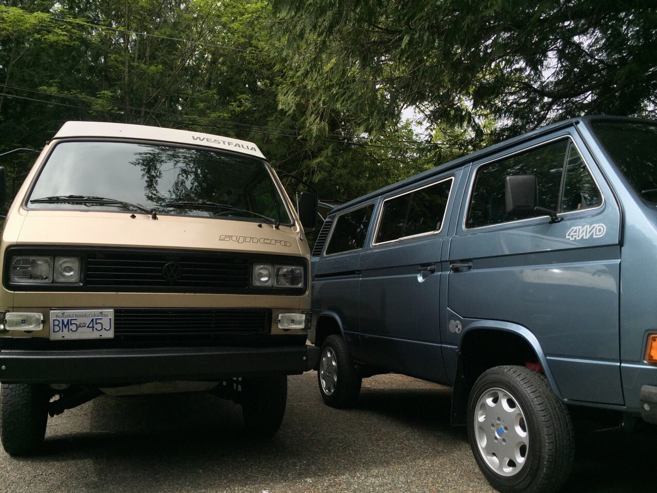
Pics sent to me by Nathan, he met local owner of this really nice blue syncro tin top. The pics tell the story.


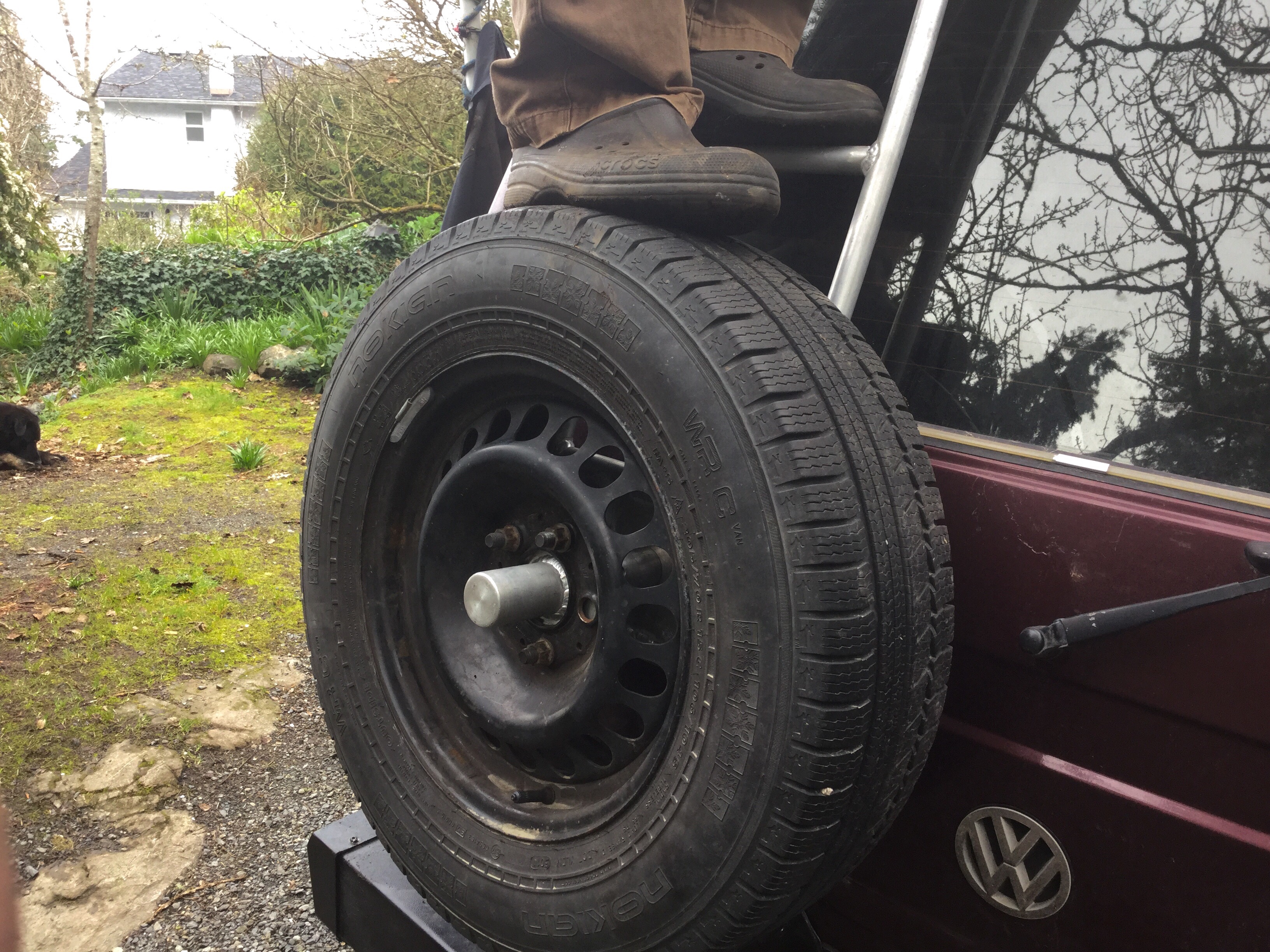
Vanagon – Nathan’s new wheels
Posted by albell in syncro, vanagon mods on April 14, 2016
I think they are 16″ Mefros. I’ll have to ask about the tires. Certainly looks perky. Hey, and note the tire carrier 🙂

Vanagon – trip to wreckers scores big, well fairly big
Posted by albell in vanagon, vanagon mods on April 13, 2016
I had the morning free to head up to Malahat Auto Wreckers here on the southern part of Vancouver Island, and I got lucky. There are fewer and fewer Vanagons in the wreckers these days, a big drop from the halcyon days of the turn of the century. But I found a tin top, year of manufacture 1991. Pretty rare here to see a 92 model year T3. The sticker said it was assembled in Austria. You know the story, the Hannover plant switched over to making T4 models and the Graz plant continued for a while to make both syncros and 2wd vans.
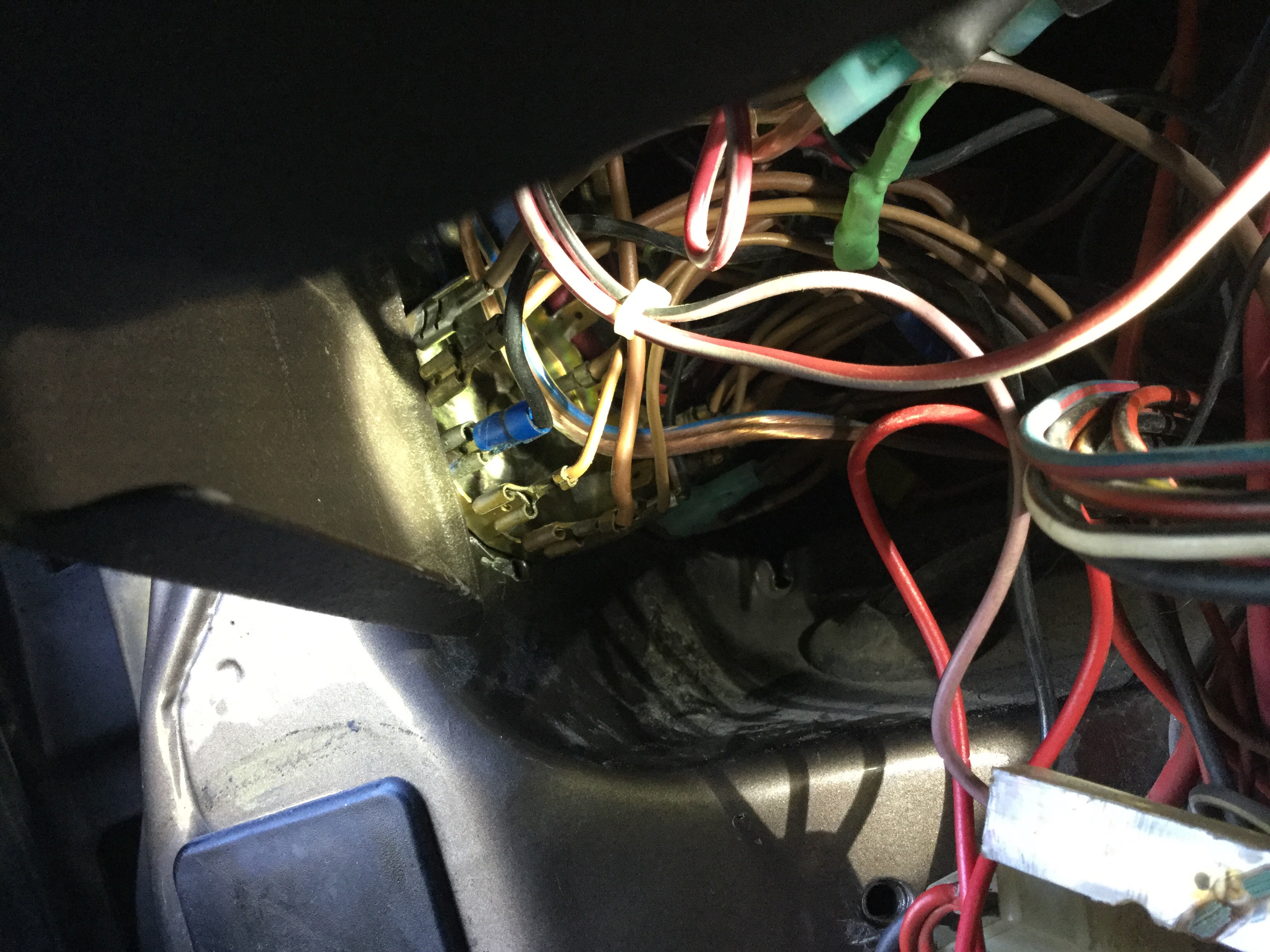
The van was in rough shape but it had the heated drivers seat intact, plus all the electrics for same. I had already scored the column mounted controller, housing, and relays some years ago but this time I got another set plus the wiring to the seat and the seat itself. The seat is pretty skanky ( and it’s blue, wouldn’t match my other seat even if it was in good shape) but I think the heating pads are salvageable.

Taking the seat apart I found that the wiring to the seat base was broken. Almost looks like it was cut. Everything else was intact and looked stock so I wouldn’t be surprised if the break was the result of some pinching and flexing. Nasty stains on the seat pad, ugh.

The seat back pad is fine.

My plan is to clean up the pads, test for continuity, remake the broken wiring, and install in my current driver’s seat. The other finds at the yard were some plastic trim pieces and the rarest of rare things, the little light above the glove box with an intact switch!

Vanagon – small led light bar
Posted by albell in syncro, vanagon, vanagon mods on April 12, 2016
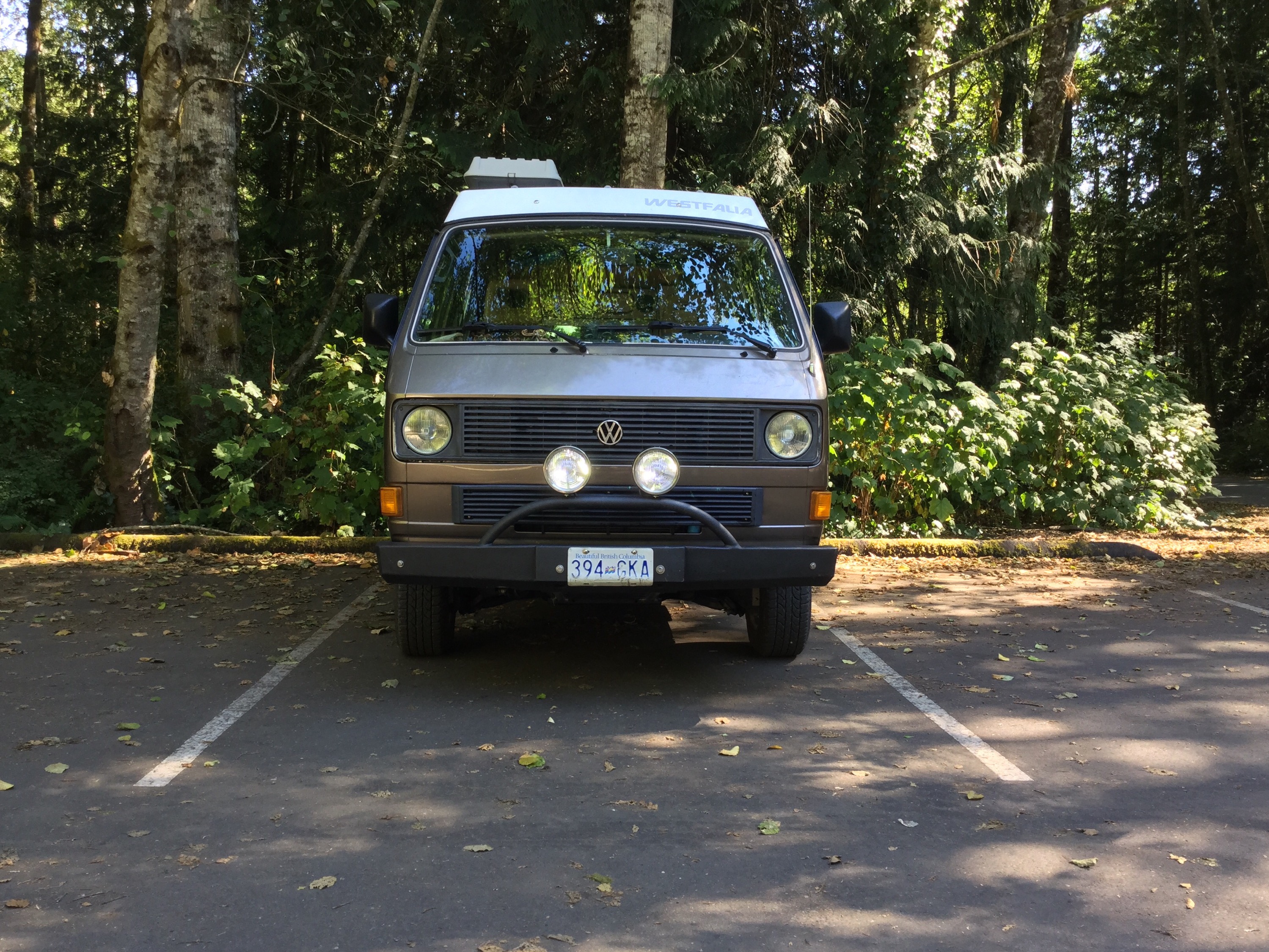
I’m getting a lot of guff about this light bar.
“oh it’s so cute”
” hey you know the front of your van is starting to look like you”
” you call that a light bar?”
And then I get this, not for the sign, but Bender’s face.

And this.

But the best one is this.

Yup, that’s it.

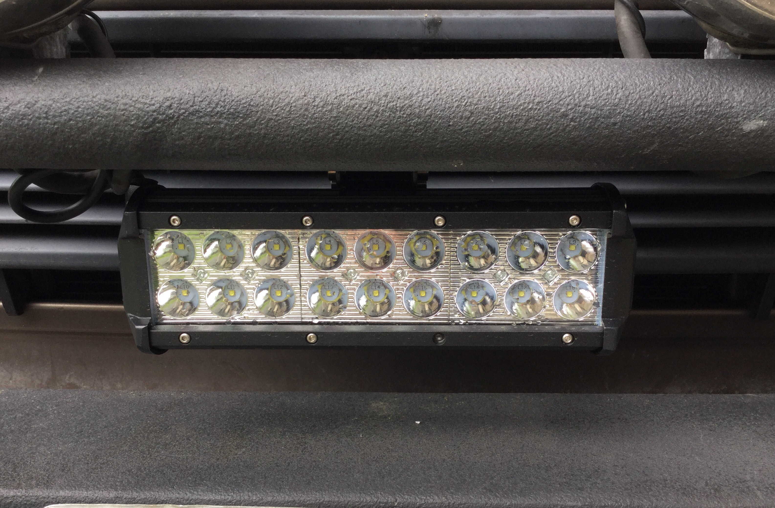
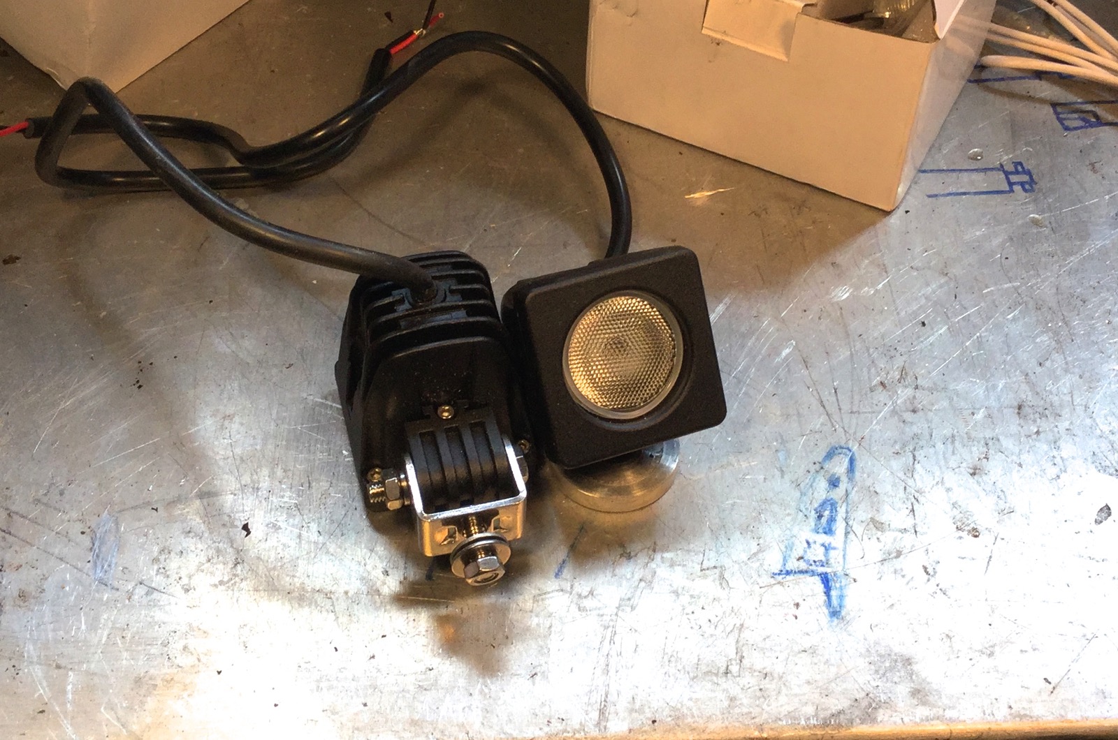
It’s this light bar from Banggood.com
54W 18LEDs Car Work Light Bar Spotlight White Projector Lamp
I chose it for its small ( yes, I chose small) size, had decent reviews, and had IP68 waterproof rating. It’s also a spot rather than flood beam pattern but saying spot does not imply that it is a carefully focused beam. My thinking was that I wanted a spot beam to project down trails/logging roads. And also I was pretty curious about these light bars. And god knows you see a lot of them on burley trucks around here. Multiples of the smaller ones, long ones that almost span the width of the truck, on bumpers, above cabs, you know the scene.
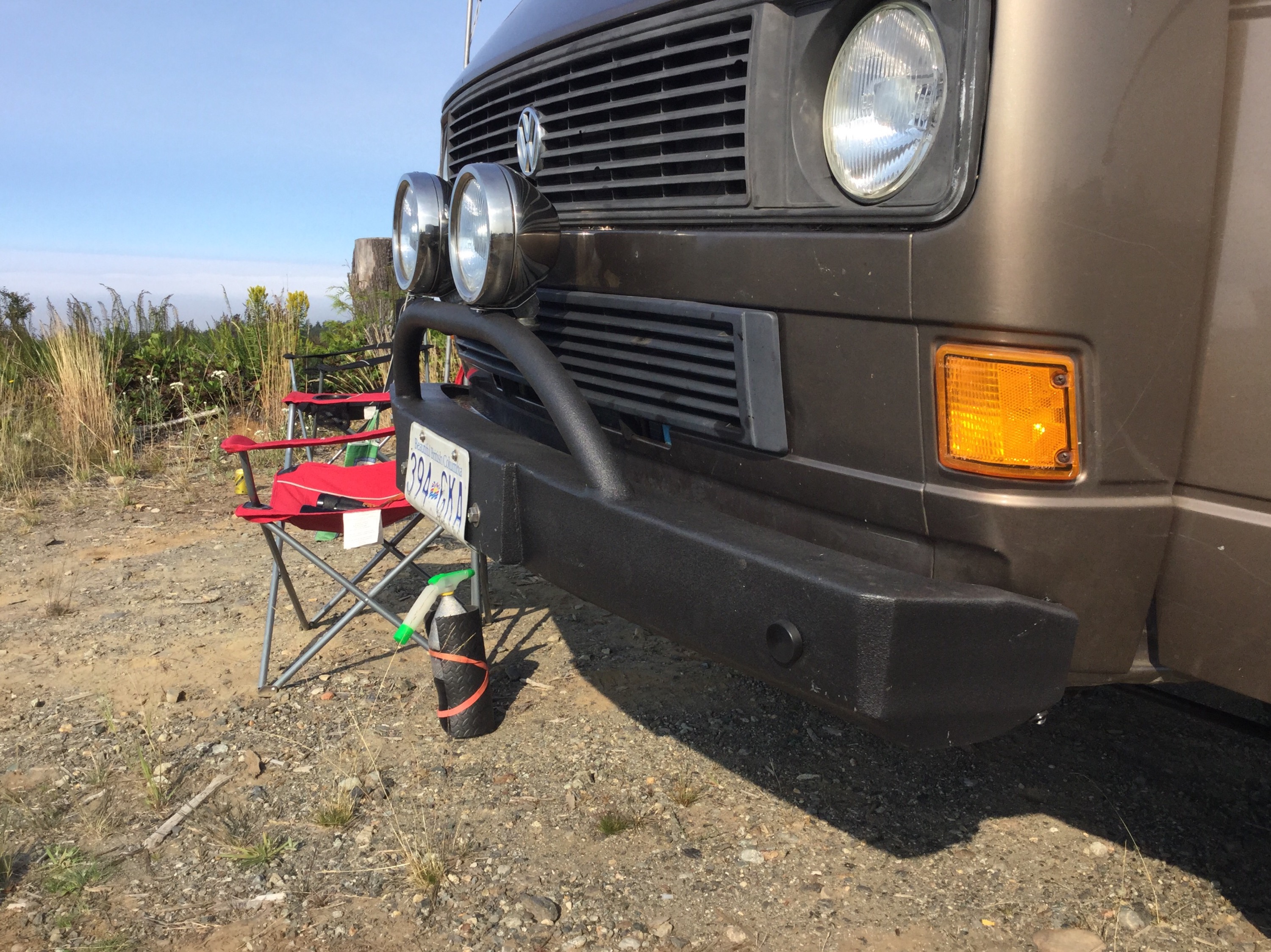
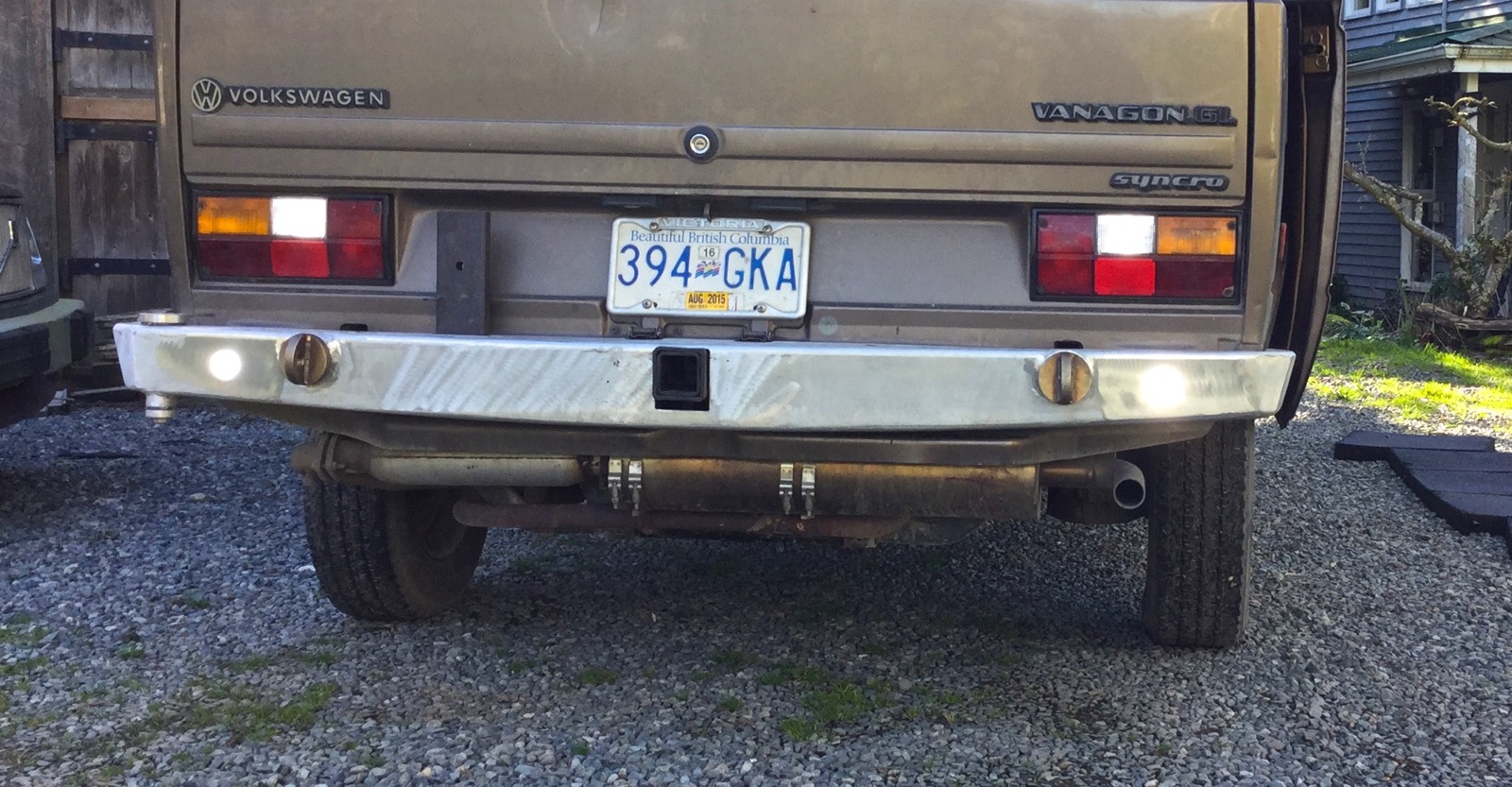
I mounted the light bar to what I call the light bar on my bumper ( getting confusing now ), power wire routed internally, ground wire attached to bumper. And I noticed that it’s missing one of the M3 socket headed cap screws on the face plate, sheesh.

Couple more pics of the ludicrous look.


Back to the wiring. Ran the power wire up into the dash, to a relay and fuse, and it’s switched on the second position of my fog light switch on dash. That’s why you see the aux lights on in the pics. They are on the first position of the switch.
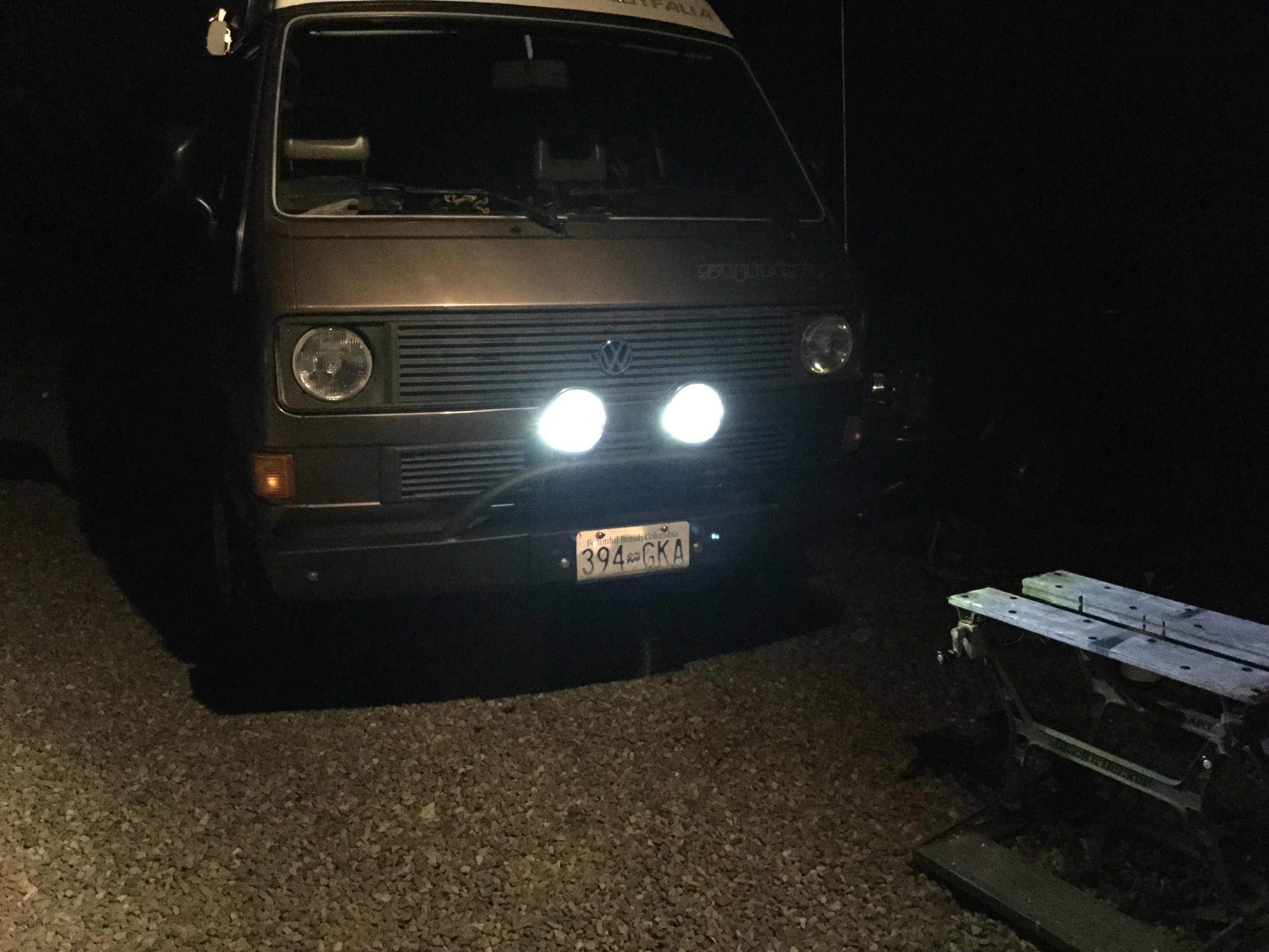
So how bright is it at night? It’s bright but not life changing bright. I took some pics but you know how that works, never really gets things right.
First pic is the aux lights alone. These are tired 55w bulbs and I have aimed the aux lights low and a little bit to the right. The aiming is little bit of an attempt to catch any suicidal deer.

And this pic the led light bar and aux lights on. The led bar could be aimed a tad higher. It’s hard to believe from the pics but you could drive easily with this light combo.

And in this pic I’ve added my main lights (high beam).

Am I happy with the light bar? Well yes, it’s fine. Good old high quality halogen spots would beat it, but for the power draw and the price I think it will do what I want it to do .
Vanagon – another ladder/tire carrier prototype
Posted by albell in vanagon, vanagon mods on April 10, 2016
Still haven’t got a production model yet, still trying things out. This one has offset tire position which I thought was a good idea, but looking at it installed I’m thinking it’s awkward.
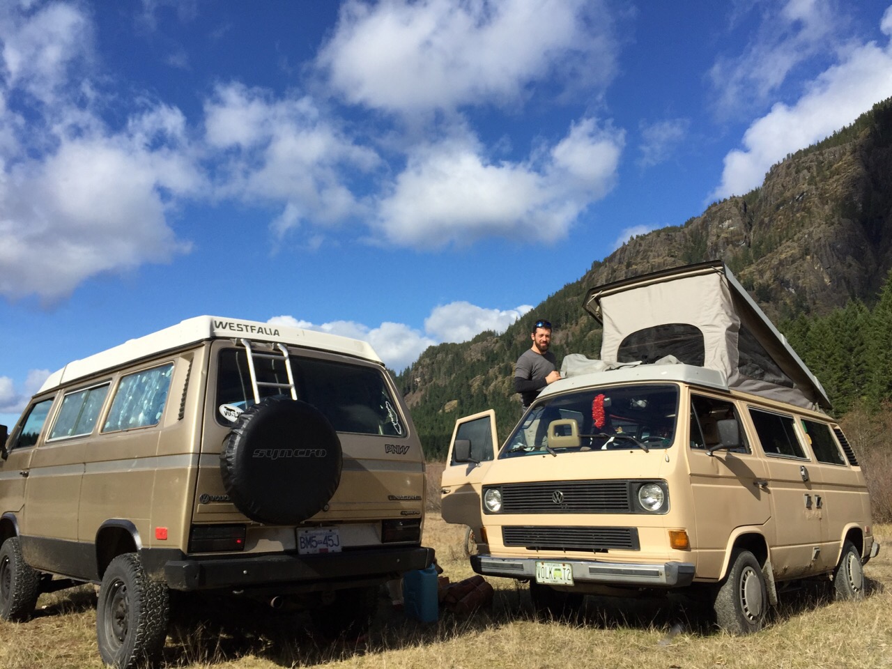
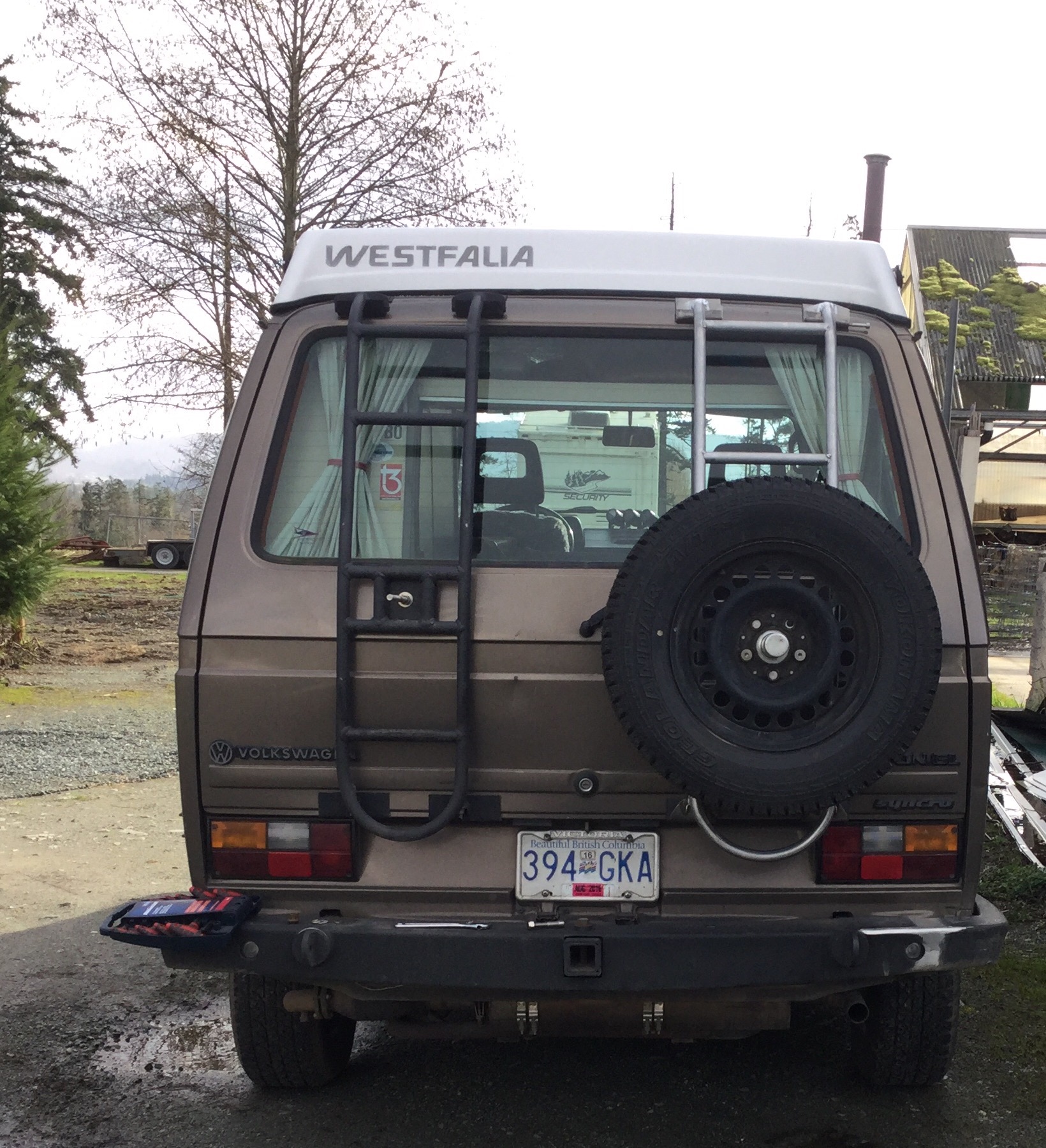
It’s on Nathan’s van. Pic of Nathan’s van beside my van kinda shows the offset and that the tire is a bit lower on the ladder. Oh and I did away with the curved bottom on this one.
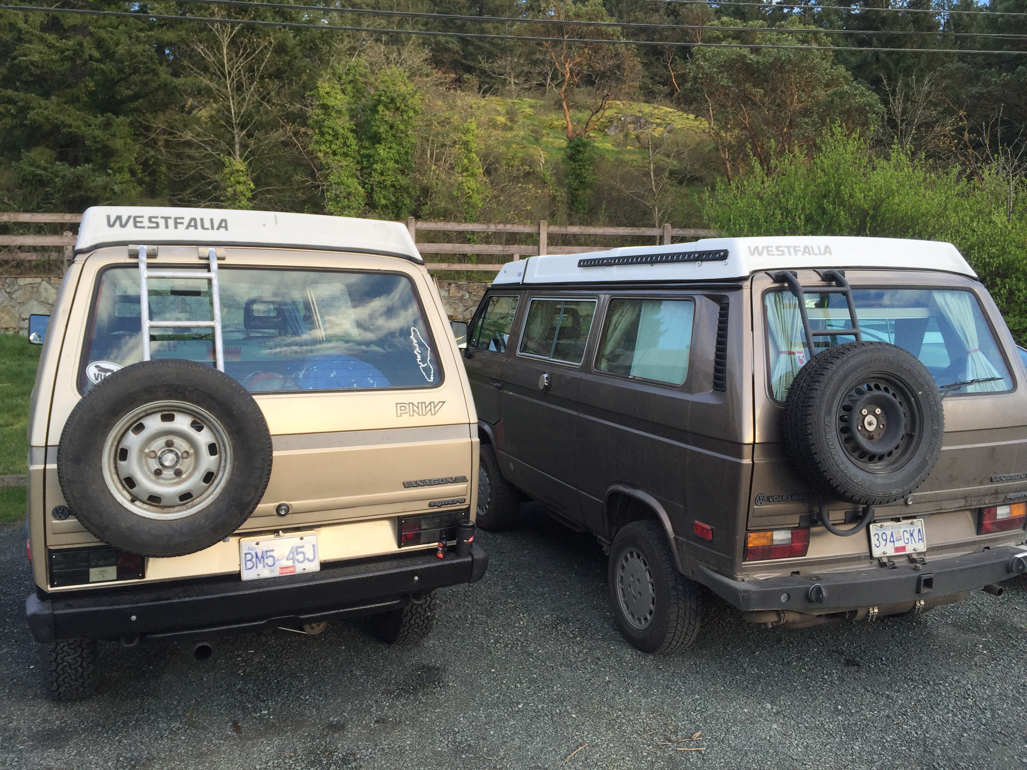
Yeah, that offset looks a little odd.

Vanagon – T4 grounding crown
Posted by albell in vanagon, vanagon mods on April 10, 2016
Hey, did you know you can just squeeze in a T4 grounding crown in the aft position of the pair of stock crowns just to the left of the fuse panel?
It’s tight, but it gets in there.
I mangled the stock crown a little getting it out. But look, look at the abundance of connections on the T4 crown 🙂
Not a great pic, but here is installed.
Vanagon – 2015 Dodge Caravan town and country second row seats
Posted by albell in vanagon, vanagon mods on April 7, 2016
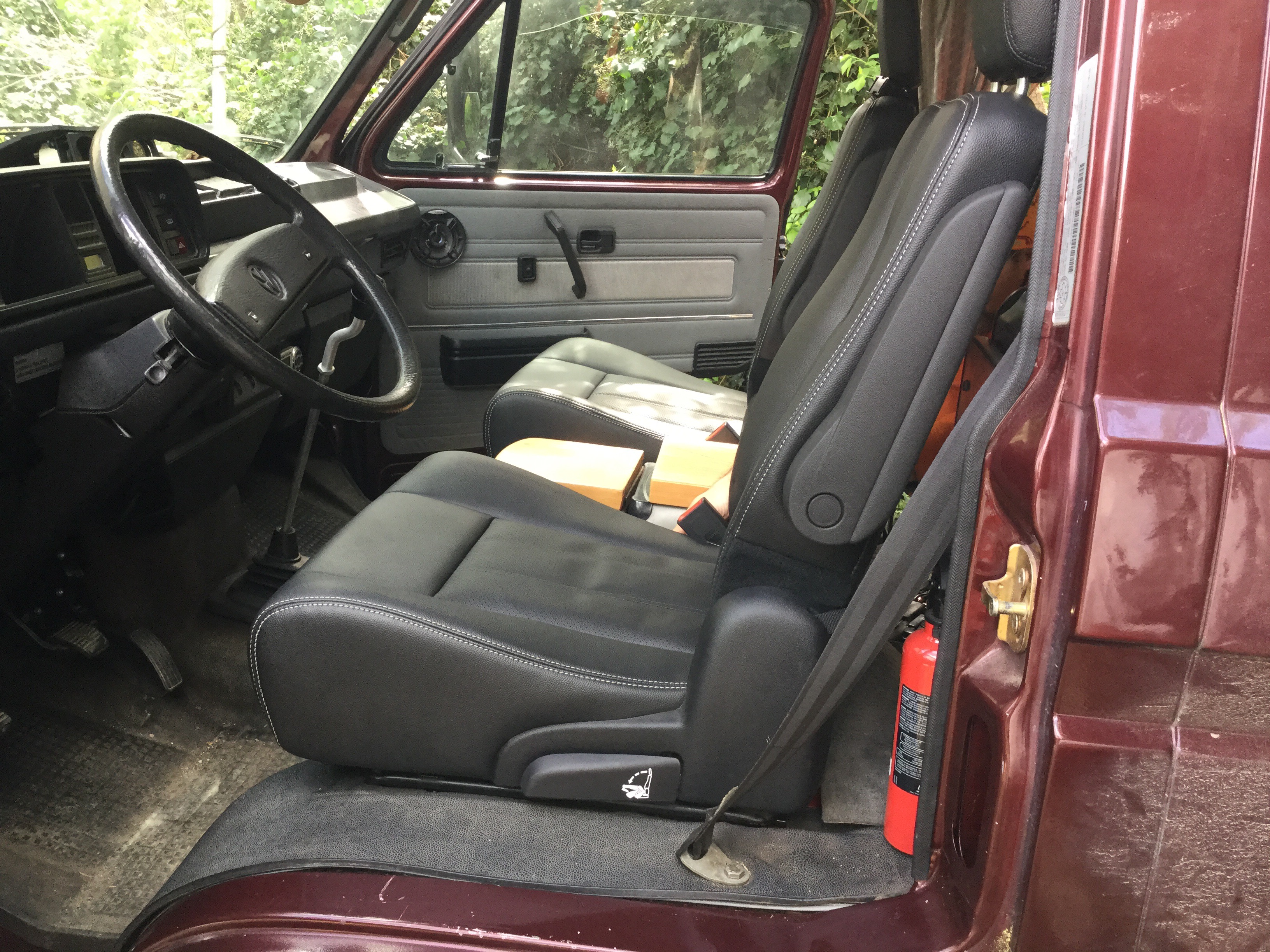
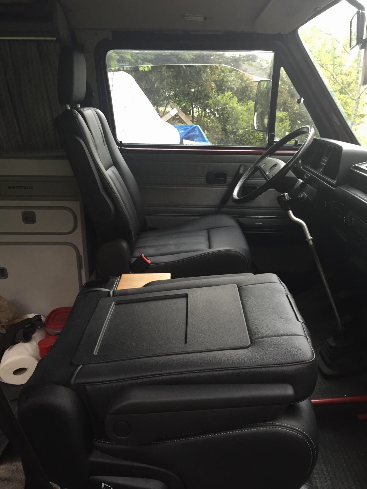
Addendum April 10, 2016. Drivers seat installed today. Simpler install, four bolts welded to stock swivel plate, 1×2″ steel box section fits onto those bolts, box section bolted to Chrysler seat. Pics at the end of the post. Oh, btw, sitting in the drivers seat is a big improvement over the stock seats. I’m 6-2, I still have a finger width or two head room to ceiling, and for some reason due to the seat adjustment or whatever, I get a much better view of the speedo and tach than I do in my van. This alone makes me want to have the seats in my van.
Addendum April 13, 2016. Some more pics taken by Simon of seats in his van, added at bottom of post.
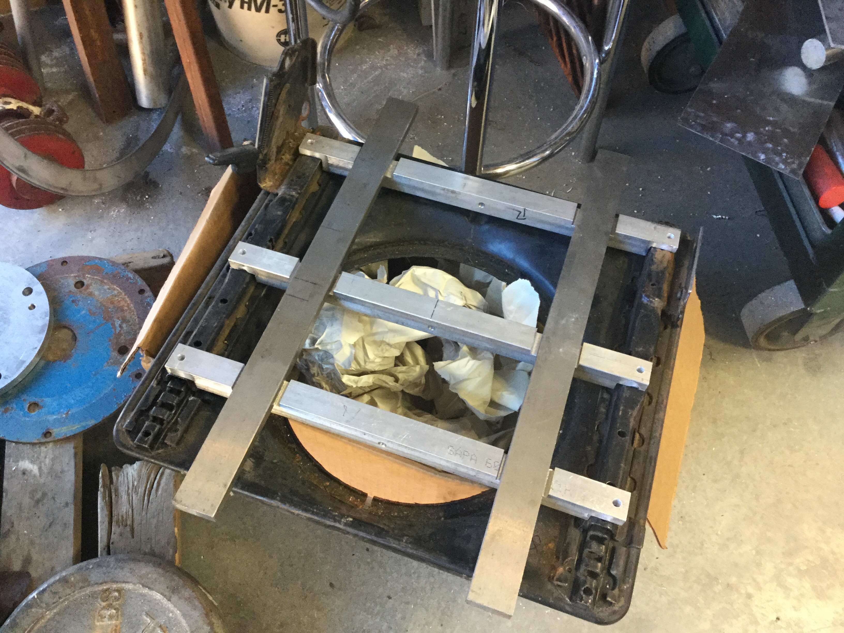
Addendum June 14, 2016. Added some pics of the aluminum rails I made to mount the passenger side seat.
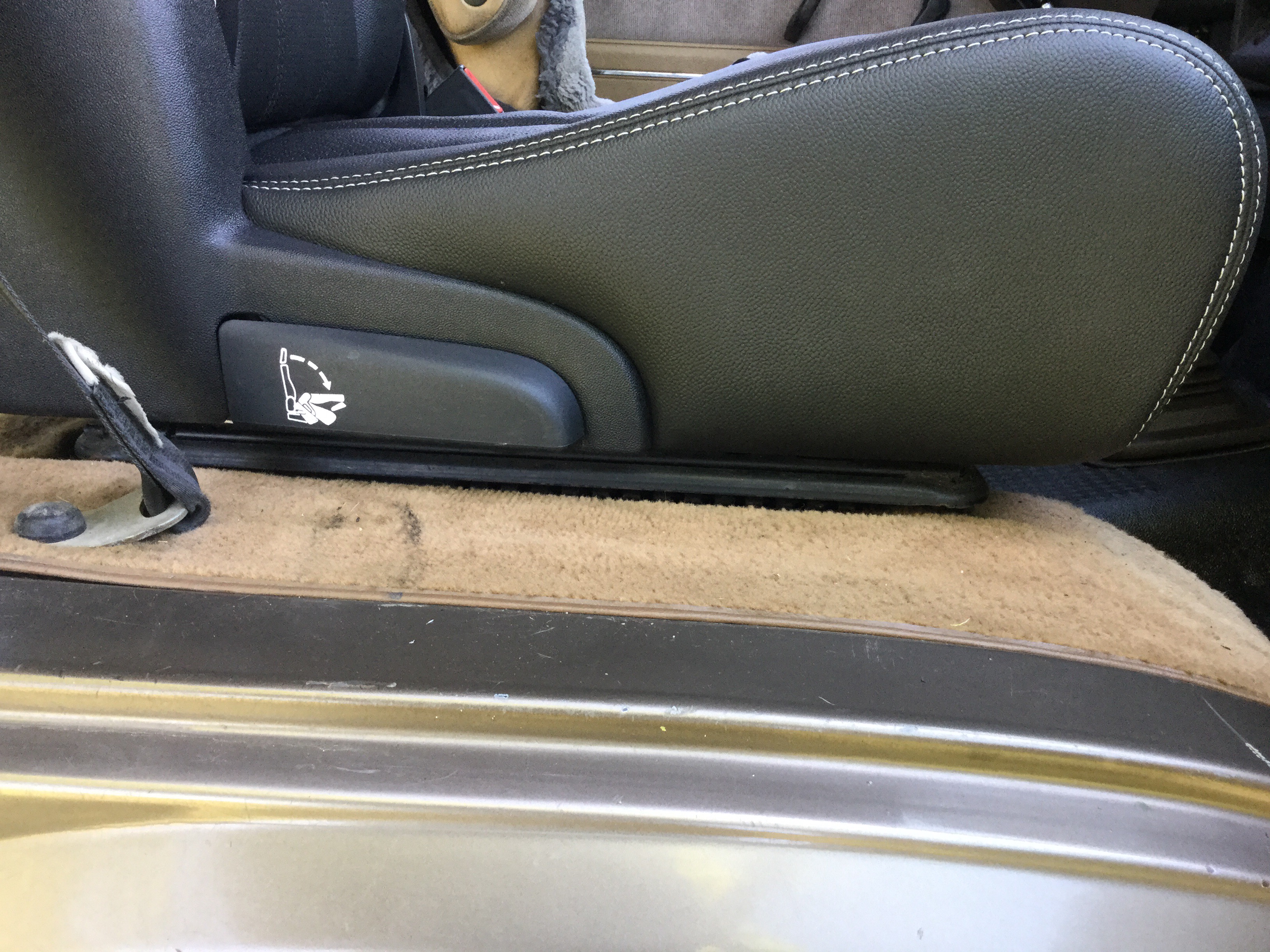
Quick post, I hope to show more details later. Adapted one of a pair of seats to fit on stock seat slider. There is a samba thread about this seat and the pioneer (link ) only used the Caravan slider mechanism in the install. Good fried Simon liked what he saw in the thread and bought a pair of seats and had the necessity of being able to move the passenger seat more, ie incorporate the stock sliders. With both sliders in action you can get a good range of fore and aft movement.
I just finished making the adapter and doing test fit in my van. The seat is more comfy than the stock seat. And it’s leather, and has heating elements ( connecting the heaters is a chore yet to be enjoyed).


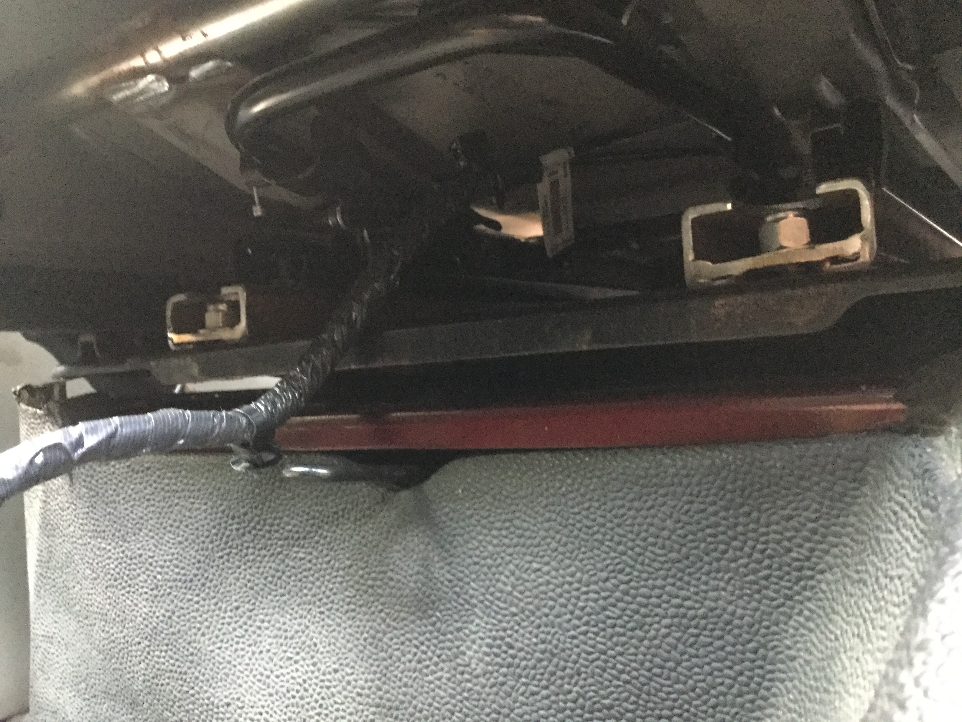


Here are some shots of the aluminum rails I made to allow stock seat sliders to be used. Note, the aluminum stock was left over scrap, the single holes in the vertical face have nothing to do with the install.
Laying on the stock sliders ( sliders salvaged from a spare seat, a couple of bars laid in the recesses just to show where the Chrysler seat rails will fit. I don’t have any more pics right now of the completed assembly including the slider release mechanism made to allow the stock slider rails to move ( the Chrysler seats have integral slider mechanism. Having the stock one too was really just to secure the stock rails). I’ll try to remember to get pics.

The longitudinal bars sitting in place. They have yet to be drilled to match the Chrysler seat bolts.
Another tire carrier
Posted by albell in syncro, vanagon, vanagon mods on March 6, 2016
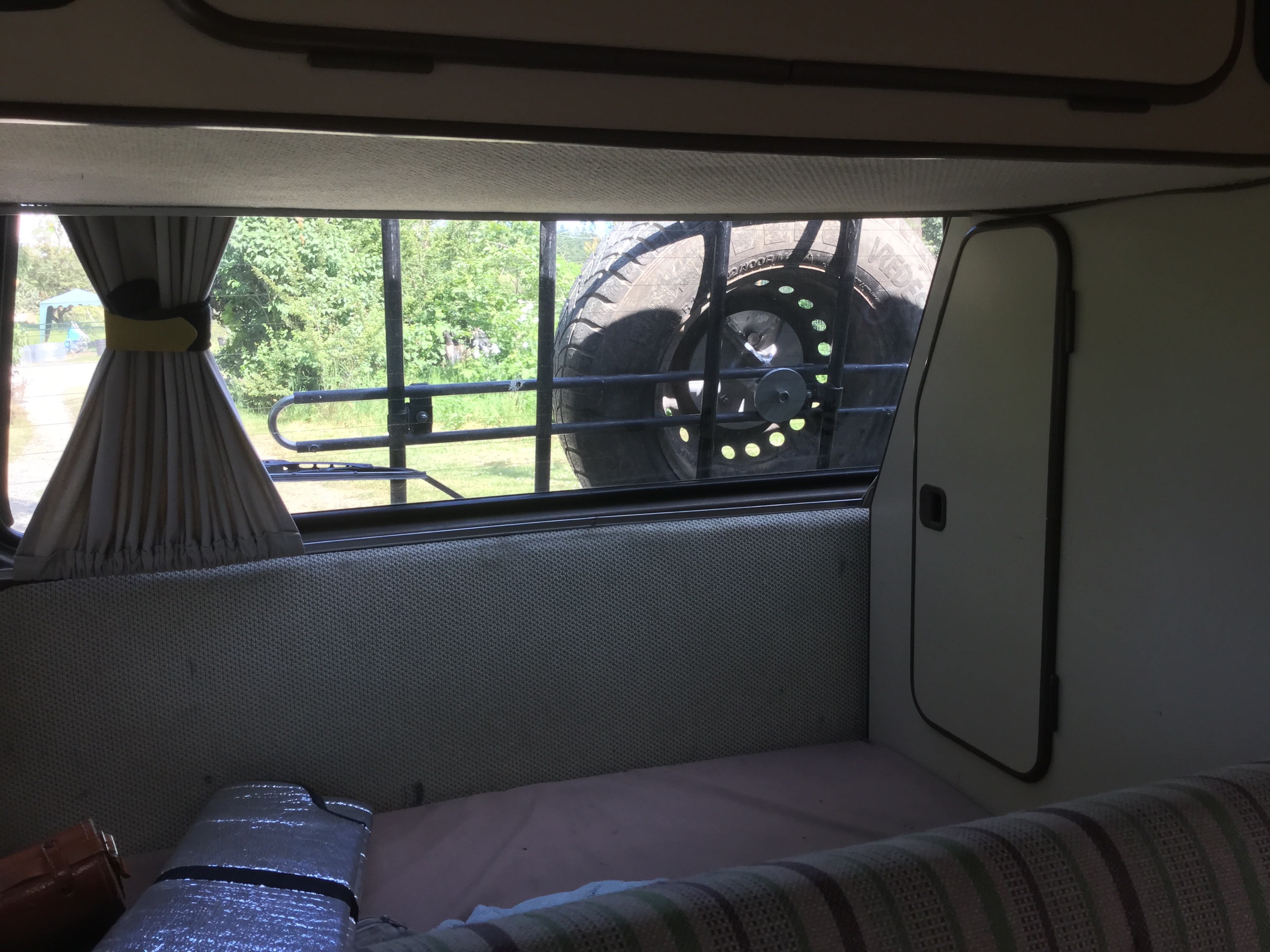
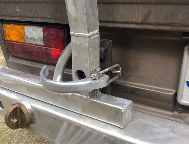
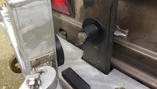
Made another carrier, for good friend Simon. Some changes made from my original. I think I have a much better hatch grabbing arrangement at the bottom. Little forward pressure on the door panel but lots up vertical grip. Tire is very solid to the ladder and the ladder very solid to the hatch. Also I repositioned the tire placement to be about 3″ lower than my original so less intrusion into the rear window.
Having the tire on the hatch is a compromise. You do need to have special hatch struts to make opening the hatch an easy process. Simon has a pair of very beefy 1250 N struts that raise the landed hatch with no effort.
The top hangers and the bottom grabber assembly is made from 0.120″ thick 316 stainless. Bolts are stainless. But the lug nuts and the mounting studs are steel.
I’m going to make some more, with some further refinements.
During the build, comparing tire placement with my original ladder.
Ditto.

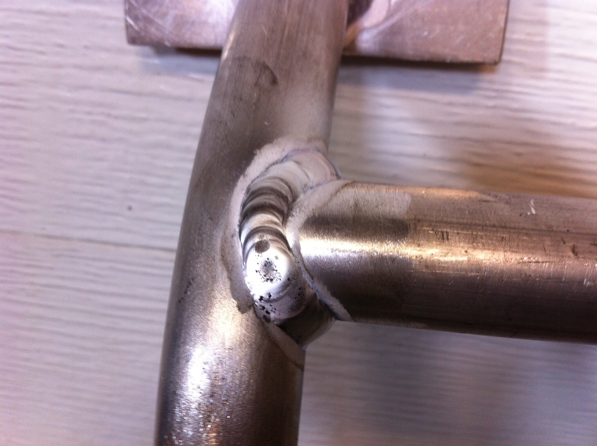
It’s 1″ tubing, 1/8″ wall thickness, 6061 aluminum. Joints coped and tig welded.
On Simon’s van. The stainless steel hangers and bottom grabbers have been painted, but the ladder itself untouched. Simon is going to paint it later.

It still works as a ladder with the tire on. Step up from the RMW bumper onto the tire.


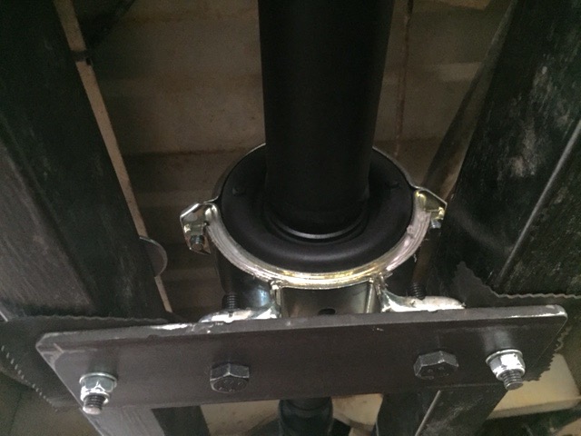
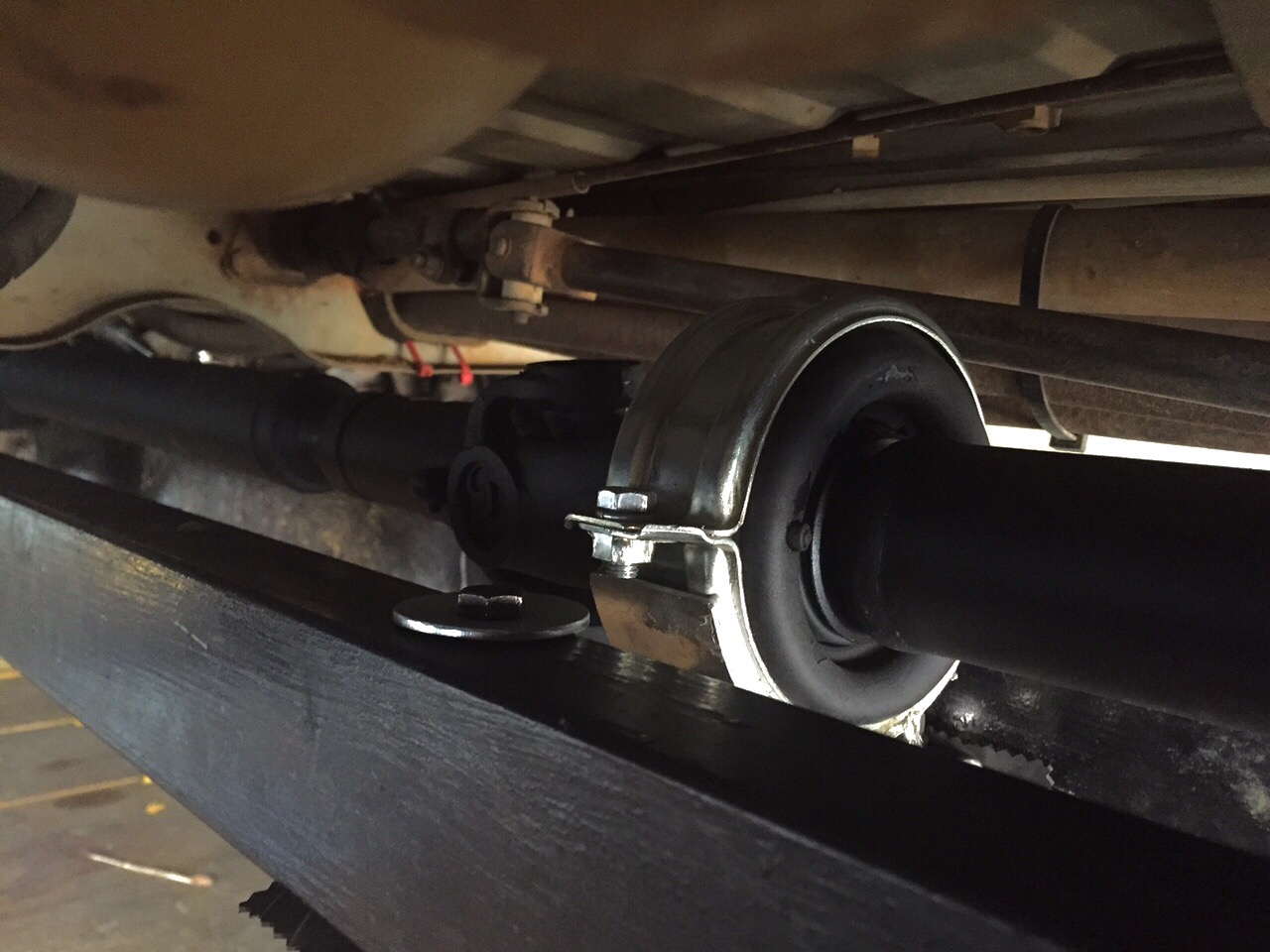
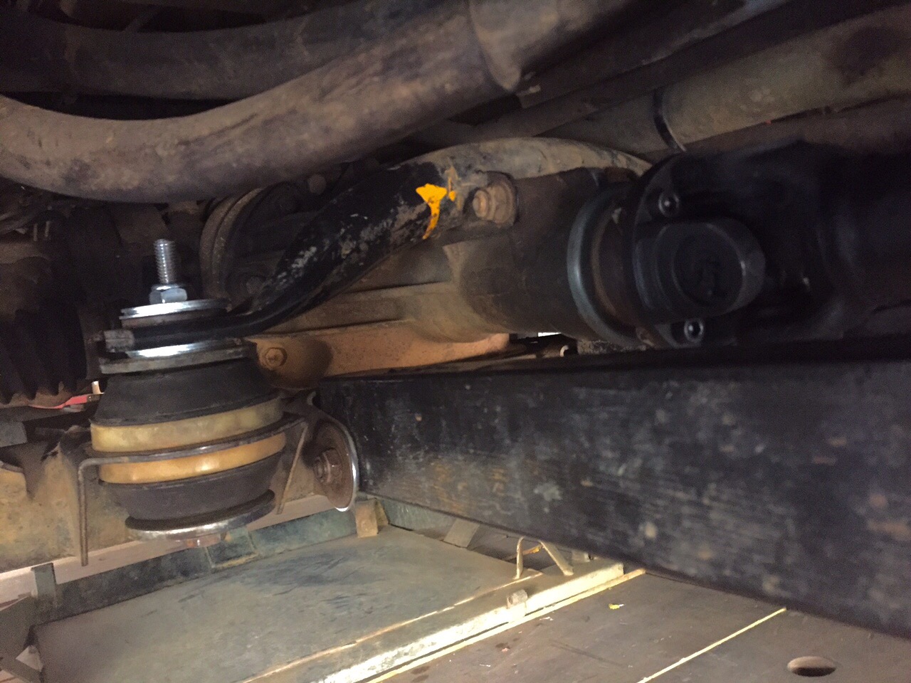
Syncro – propshaft with intermediate bearing support
Posted by albell in syncro, syncro specific repairs, vanagon mods on November 22, 2015
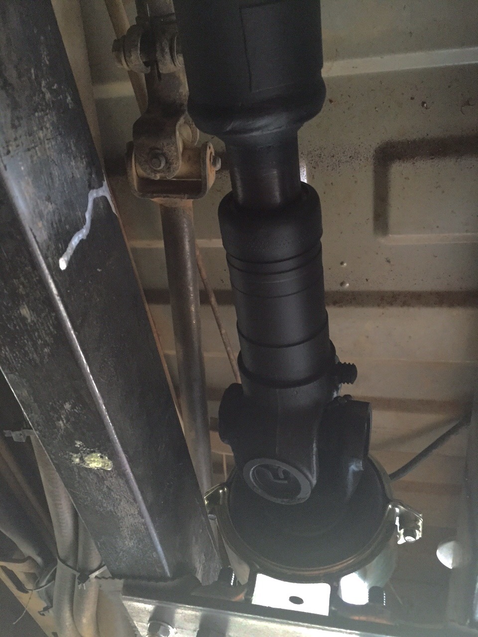
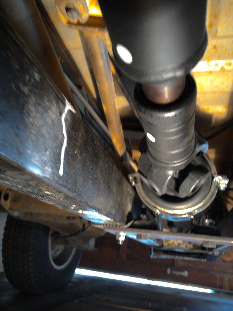
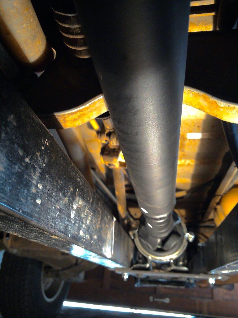
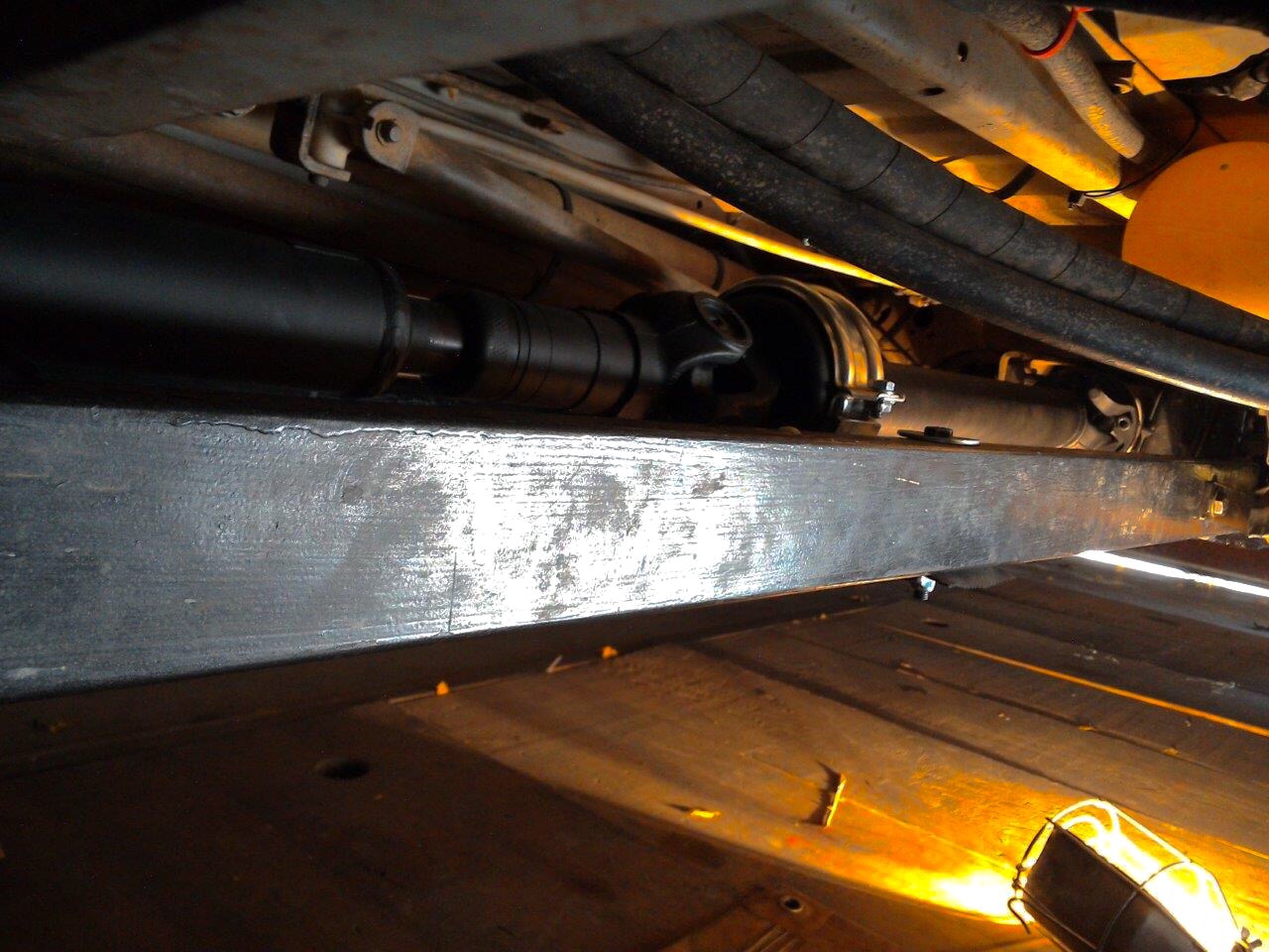
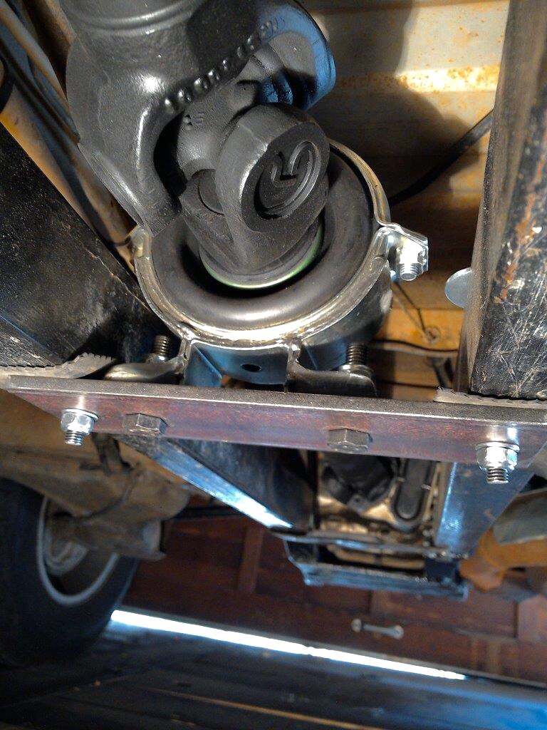
John B. sent along some pics of his new propshaft. He was having some difficulty in getting the stock set up running vibration free so he went this route.
Due to some errors on my side, I can’t find his emails where he described the set up. Until I get that info I’ll post the pics as is.


Addendum.
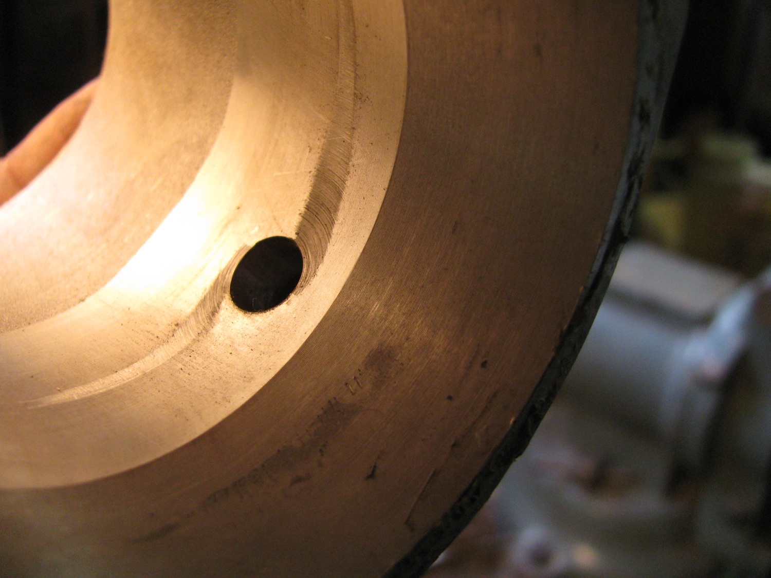
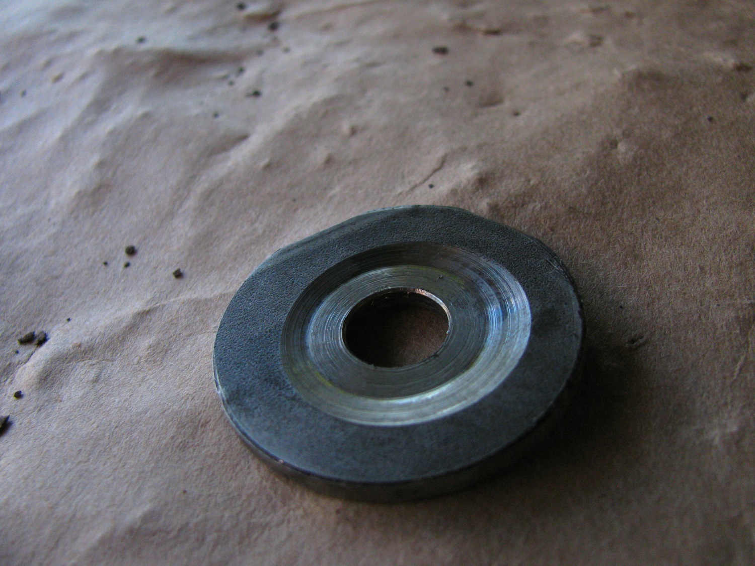
In reply to Hans’ comment about CV jointed prop shaft. A couple of pics. First is the flange of my spare propshaft. Approximate measurements make it a 74mm bolt hole circle, the recess is 47mm diameter and about 2.5mm deep.
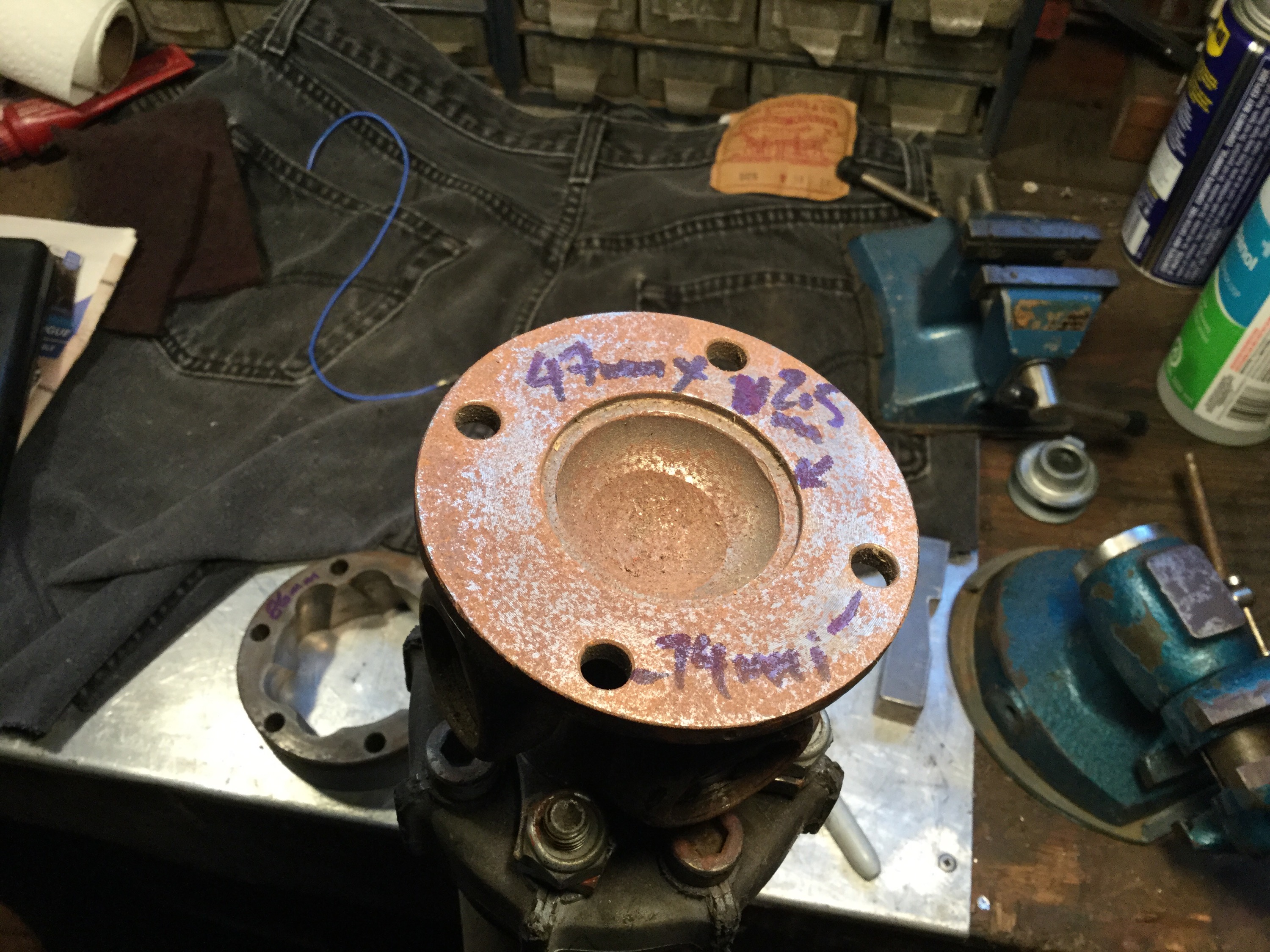
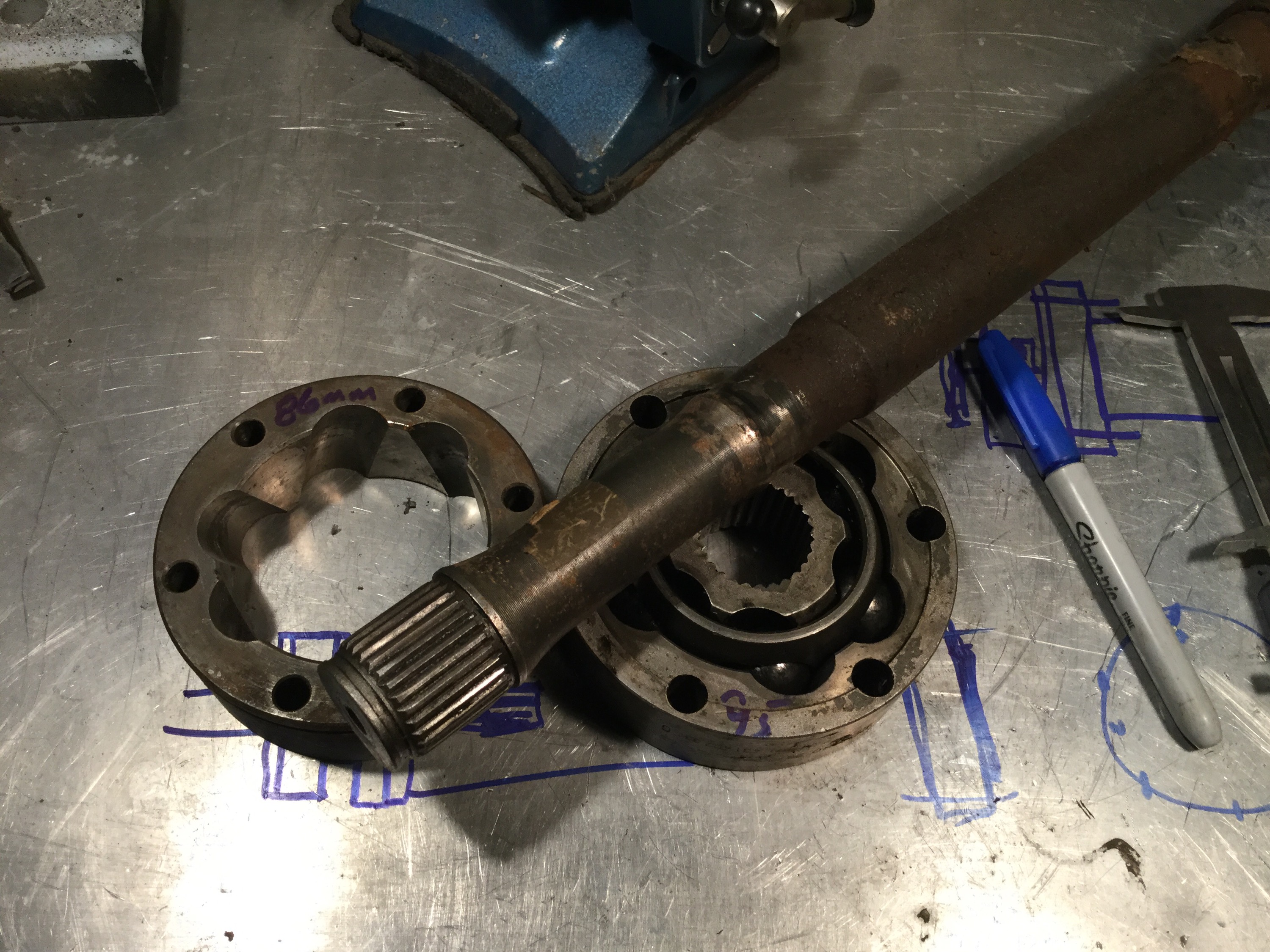
Stock 100mm diameter cv joint has a 6 on 86mm bolt hole circle.

A 108mm diameter CV joint, has a 95mm bolt hole circle.

I have the half shaft for that 108mm diameter CV joint. One could imagine cutting the spline section off and mounting it to a flange that mimics the stick propshaft flange, then the slides connecting to the 108mm diameter CV joint bolted to the propshaft. I hope you understand this is all just free thinking, just for discussion.
Vanagon – front bumper pics
Posted by albell in vanagon, vanagon mods on August 5, 2015
I’m declaring it done, well almost. Still fussing with ideas to cover the exposed bolt heads. I’m going to give it an 8/10. It is doing what I wanted it to do, but I really don’t like the end caps very much. I found it hard to enclose the “C” shape of the bumper because I carried the bottom angled section of the bumper right back to the standing seam on the body. It made for a big cross section to enclose at the ends. I added facets to the endcaps that really don’t do much for looks. Also noticed after painting how my casual approach to finish grinding and a little warping due to welding gave the top surface the hint of downturn towards the ends. Mostly this is a visual due to the sloppy finish grinding on the top edge. But now my eye is drawn to it and I get that pang of regret.
Oh well, that’s how it goes, I have to see the thing made then decide what I like and don’t like 🙂
The light bar worked out ok. Places the lights approximately in front of the metal section between the upper and lower grills. One could argue that the lights are too close together, but I’ll leave that conclusion until I aim the lights and do some night driving.
As for the lights, I did manage to shoehorn the 6.5″ H4 lamps into the housings. Right now I have it wired to the fog light switch and only connected to the low beam filaments in the lamps. I plan on connecting (yes, of course relayed) to the hi-lo stalk switch so I can have both high and low beam auxiliaries. The lamps had city light bulb holders in them. I replaced them with 2W led eagle eyes. I wired them to come on with key on, thinking they might make DRLs. Not quite bright enough, but certainly noticeable. The night shot shows them on, appearing more brilliant than they actually are. I’ll see if I can dig out some pics I took months ago showing the eagle eye install. I’ll update this post then.
Wiring to the aux lights runs inside the light bar and out behind the bumper. The nice flat top surface really makes it easy to stand on to get things on the roof. The paint is rubberized rocker guard paint. Yes, not bedliner. I thought it would be be a better choice for touch ups after the inevitable scrapes on rocks. Certainly less expensive than bedliner. About ten bucks a can, took two cans to do the bumper. Aluminum was prepared by scuff sanding and acid based aluminum wash. Then one coat of self etching primer and about three coats of the paint.
I should mention how I mounted them to the sub bumper. The stock mounting holes (M10x1.5 I think) got reworked with helicoils for M11x1.5. I made a stainless steel bracket, like two “C” shaped pieces connected by a straight section out of 1/8″X1.5″ bar stock. The “C” parts fit over the sub bumper and are held onto it by two bolts running vertically down through drilled holes in the sub bumper. The bolts hold the brackets in place and also pinch the sub bumper a bit, pretty solid. On the back of the rackets I welded nuts for the M13x1.75 bolts that go through the centre section of the bumper. Trust me, the bumper is on there solid.


Vanagon – soft shackles on tow points?
Posted by albell in syncro, vanagon, vanagon mods on July 30, 2015
It might be a good idea, it might not. 1/4″ Spectra soft shackle to be used on the rear tow points of my bumper. On this example I have yet to trim the tails, I need to give the shackle a good pull first. one nice thing is that they pack into small spaces unlike a steel shackle. Note: 1/4″ Spectra has breaking strength of 6,000 lbs. tests have shown a soft shackle doesn’t decrease strength (infact, it can be 175% of single line strength). But, 5/16″ Spectra tests at 9,000 lbs, might be better to use 5/16″.
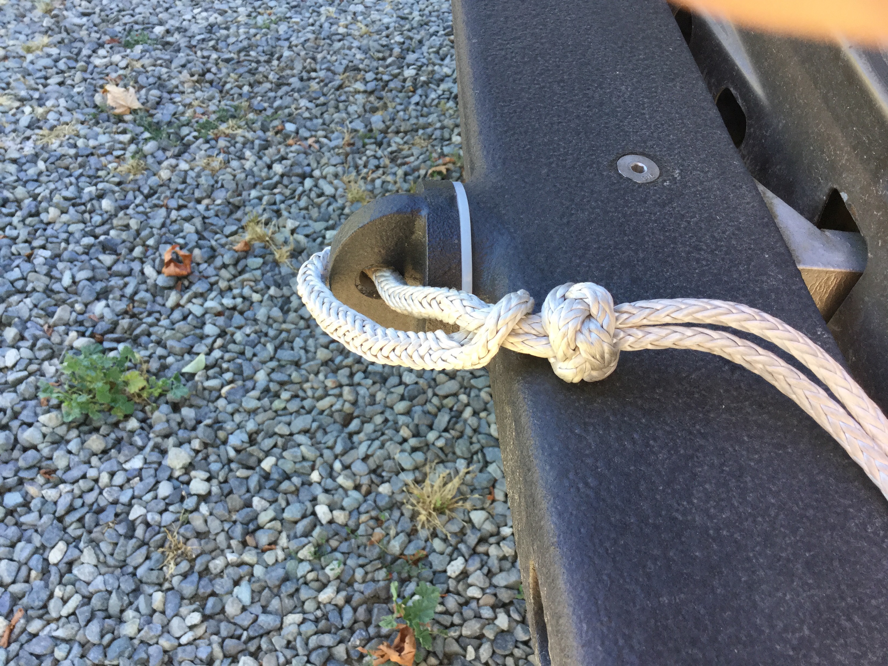
Here is link to instructions to tie this particular style.
Vanagon – aux battery, solar, and aux wiring diagram update
Posted by albell in vanagon, vanagon mods on July 28, 2015
Whoops! Uploaded the wrong diagram, hold on….fixed
I redrew my schematic to show changes made in the last year. I dropped the Doc Watson meter, added solar panel controller, and added large fuse at the big aux battery. And I added a 15A fuse on the small wire that runs from the ACR to neg return. It’s a safety in case of an internal fault in the ACR. Also, I corrected mistake in last diagram where the ACR was connected incorrectly to the aux fuse panel. Now you see it is fused at panel. I should make it clear that I do not have a power feed to the fridge cooling system. I may add that later, but I don’t miss it.

Vanagon – rear side marker light guards
Posted by albell in vanagon, vanagon mods on July 23, 2015
i made a few prototypes, aluminum with quick spray bomb paint. What do you think, silly, sensible, or none of the above?

Update, in a way.
Still fooling with the idea. Made this version to see how a swing away guard would work. The proportions are a bit screwy but I like it enough to to try again.


Vanagon – front bumper build pretty well done
Posted by albell in syncro, vanagon, vanagon mods on July 22, 2015
I’ll get better pics and notes when I wire up the auxiliary lights on that light bar.


Vanagon – hatch mounted spare tire carrier
Posted by albell in syncro, vanagon, vanagon mods on July 12, 2015
Last spring I finally gave up on my swing away tire carrier project. I couldn’t get it stiff enough for my liking. I’ll post something about that fandango and my new front bumper later. The stock location for the spare was taken over by the big assed battery so I have been using a paulchen rack to carry my spare. I really didn’t like that and last week I made a quick and dirty aluminum ladder type rack to carry the spare. I’m going to give it a bit of testing before clean up and painting, then I will post more on construction details etc.

Vanagon – some notes on new wheel install
Posted by albell in syncro, syncro specific repairs, vanagon, vanagon mods on June 26, 2015
i bought the Mercedes alloy wheels last year. They weren’t my first choice, I wasn’t really sold on the flat face look. But the price was right ($100 for 4) and I thought the offset of 25 might work out for me. The ideal offset would have been 30mm, but folks have successfully used ( without wheel spacers) wheels with offset of 37mm on the syncro. Mind you I think those wheels were narrower than 7″.
The whole subject of wheel choice can be confusing. Chris at T3 Technique has good information (link) and there is a very lengthy Samba thread on the topic.
With the alloys having an offset of 25mm I wasn’t concerned about clearance issues with suspension components but I was a little nervous about how much space there would be between the sliding door and the passenger side rear tire. As it turned out there is a good 3/8″ – 1/2″ space between tire and door.
Some time after I bought the alloys, good friend Simon bought a set of Mercedes 15″ steel wheels. 6.5″ wide, offset of 37mm. He offered them to me, we thought that maybe the black steel wheel look would work on my van. If they did both of us would use one of the alloys as a spare, if not then the steelies would be out spare. Simon needs a better rin for his spare.
I had one of each type mounted with tire and compared them on the van. The alloys won. The clearance between the steel wheel and both the front and rear suspension components was tighter than the alloy.
As the alloy wheels have a thicker cross section where the wheel studs locate I had to get longer studs. Well on the rear wheels anyway. The studs are a tad longer on the front wheels so I left them stock. I measured and determined I had 8.75 turns on the lug nut on the stud as it tightens up to the wheel. The thread size is M14X1.5 so that gives 13.13mm of engagement which I think is sufficient . Replacing the front studs on the syncro is a pain. Note that various alloy wheels differ in thickness in this area, some are quite thick.
I got the longer studs from Chris at T3 Technique, hands down the best source for wheel hardware. I had a spare set of rear hubs so I had the studs pressed in, sitting around waiting until I got off my duff.
Also, the lug nut seats on the Mercedes alloys were the small ball type, the stock steel wheels on the Vanagon use large ball seats. So I had to buy some new lug nuts and yes I got them from T3 Technique. Here is a pic comparing the stock Vanagon lug nut to the lug stud that came with the alloy wheels.

And one more thing to do. The Mercedes alloys are drilled for 12mm studs. The Vanagon uses 14mm studs. I enlarged the holes with a 37/64″ drill.
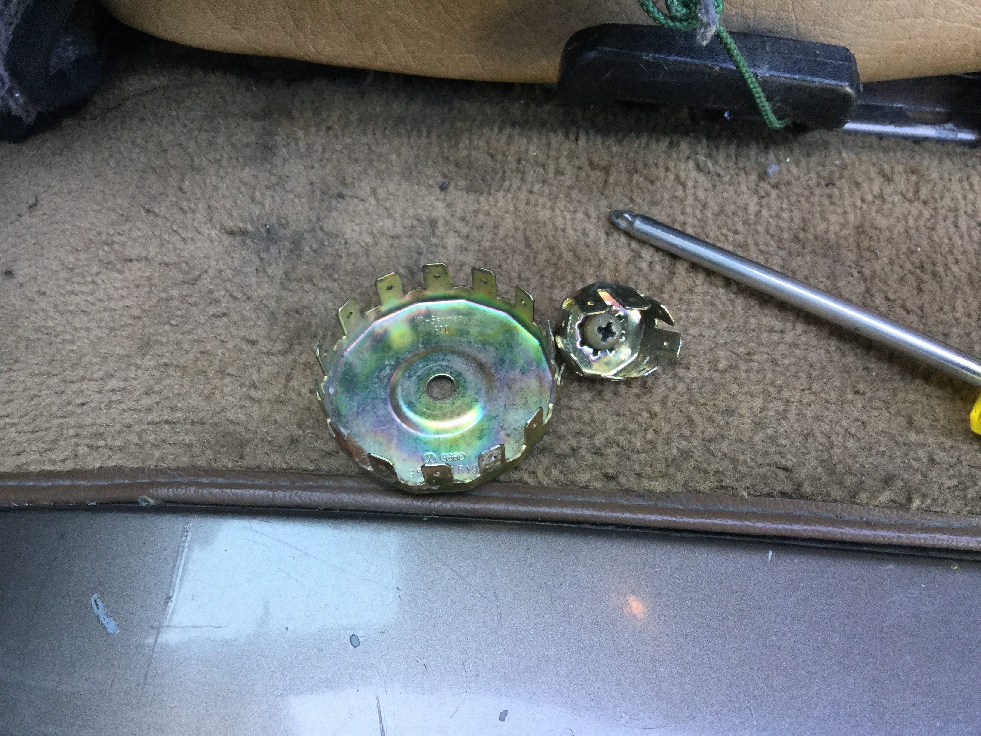
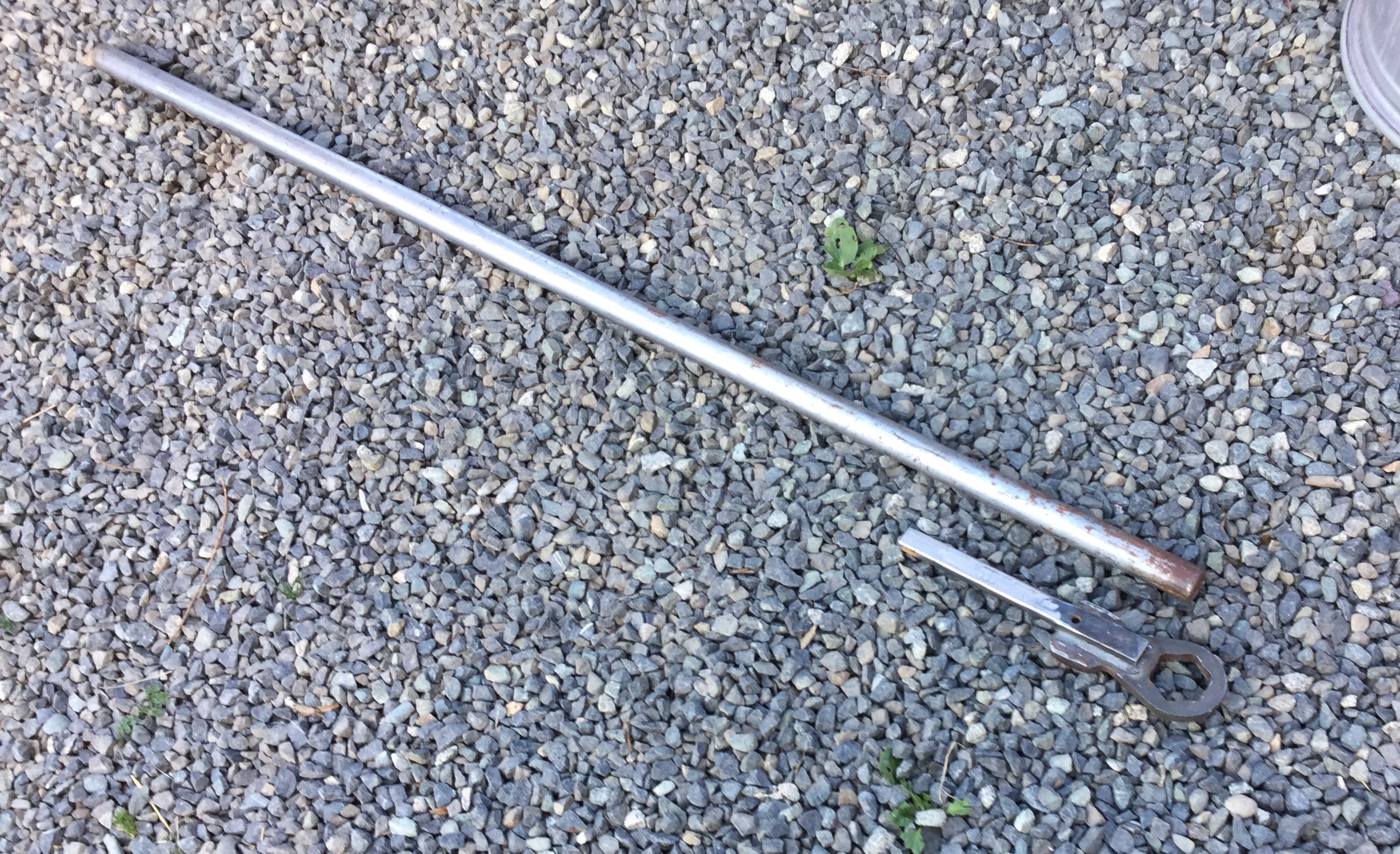
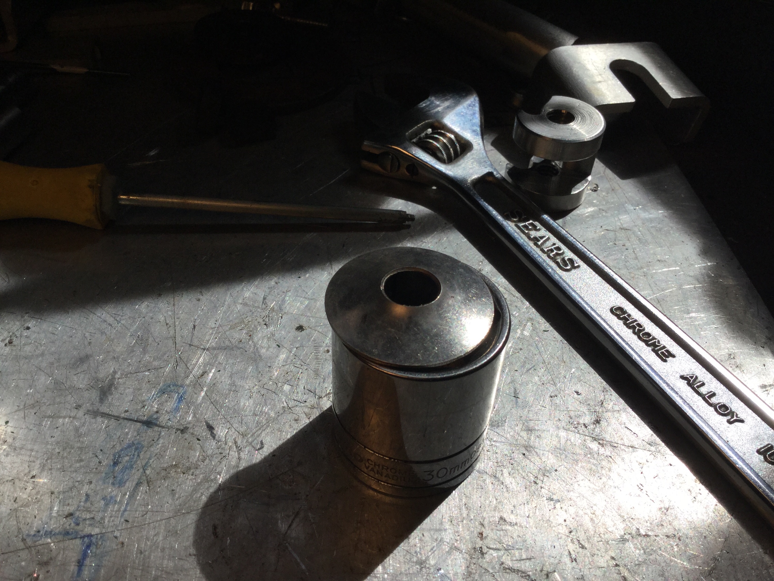
I had a bit of fun getting the hubs off the van. I’ve done this job a few times but this time the big 46mm axle nuts were very, very reluctant to come off. What I normall use is a 1 13/16 socket, 3/4″ drive but for the life of me I couldn’t find the 3/4″ extension and T bar for the socket. So I thought I’d be clever and modify the 46mm slugging wrench I had. Btw, I have a hard time using the slugging wrench in the way it is supposed to be used. I find it hard to get a good swing at it with the heavy hammer without hitting the wheel.
I welded a bit of 7/8 hot rolled steel to the wrench, and that spud fit into the 5′ steel tube I use as my might extension. Well, the hot rolled bent immediately. Ok, I cut it off and welded on a found section of bar stock. I had the notion that this particular bar stock was perhaps a stronger steel.
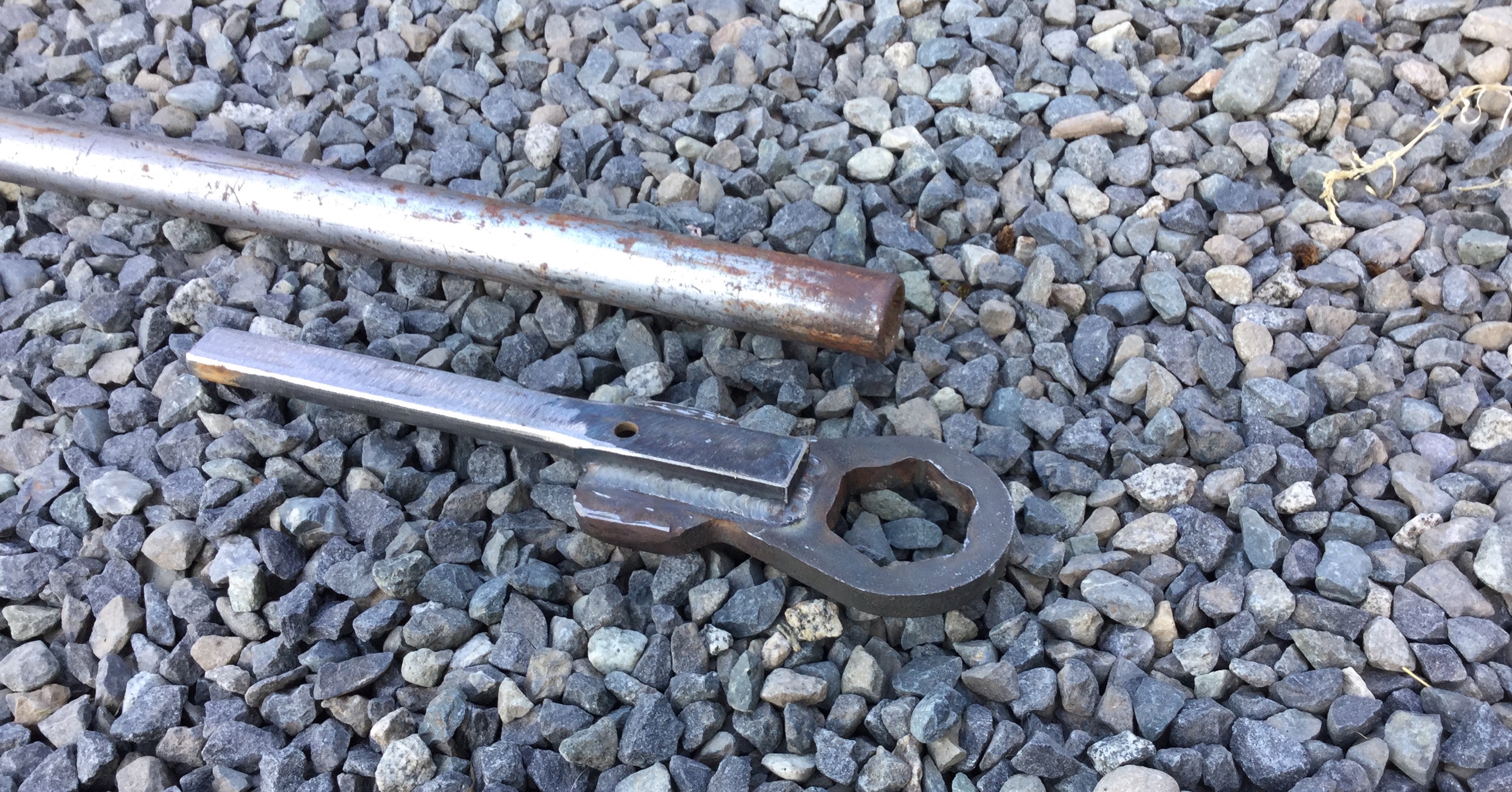
Why the heck did I weld it on with the hole at that end? I can’t explain this bozo move.
Well that shifted the rig hand side axle nut, but it bent a little in the process.
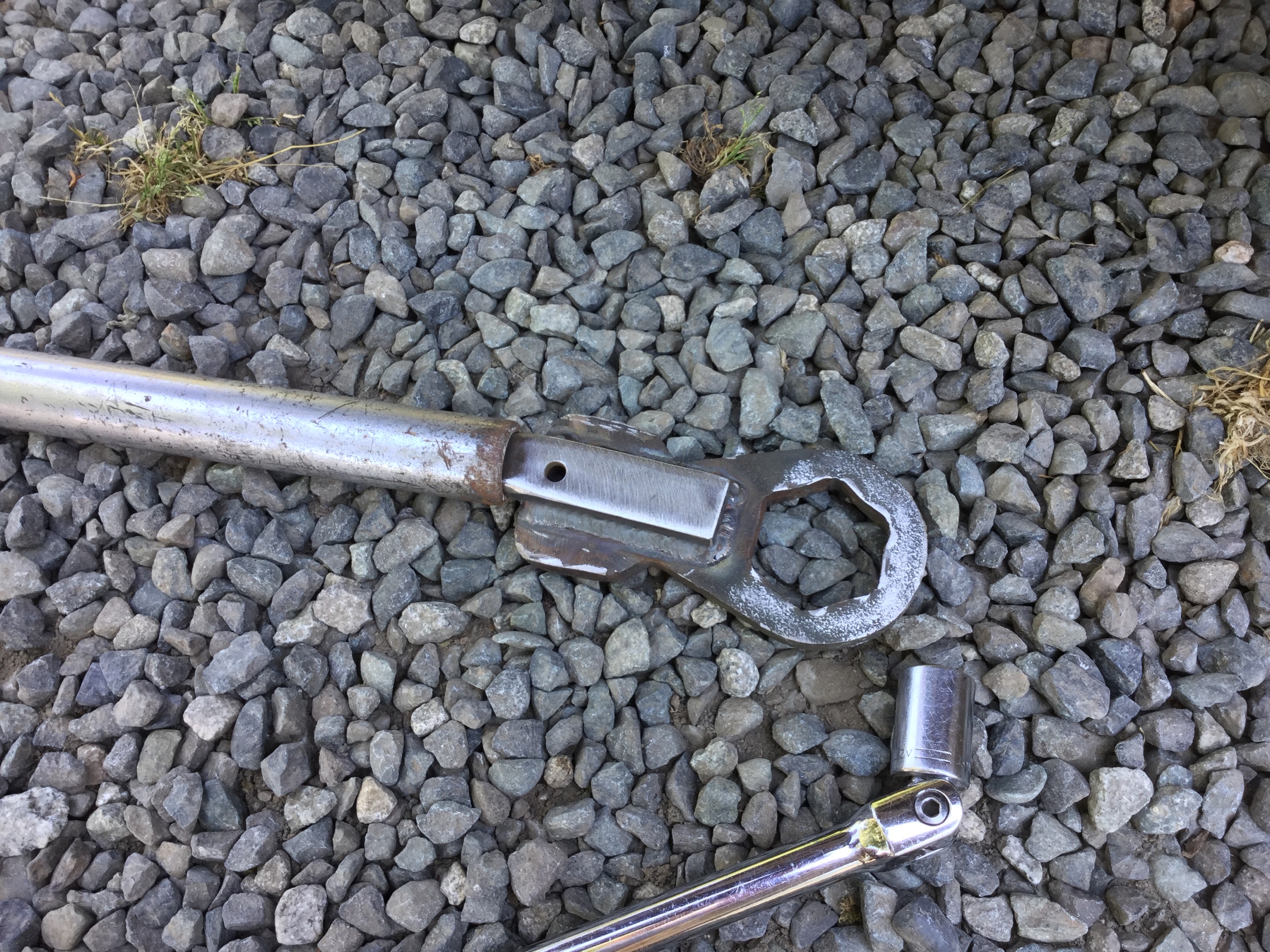
And the hub swapped.

But Mr Wrench (and my weld at the end) was not up to going after the other side.

I nipped over to a friend’s shop and he easily loosened the nut with his Milwaukee battery powered impact gun ( has 1100 ft lbs of torque).
Mr Wrench was still strong enough to re-torque the nut to the 365 ft lbs the bugger needs. I added a bit more weld in the hope that I can use him again sometime, in his new cranked conformation.


I’ve yet to get some good shots of how the wheels and tires look on the van. In the meantime here are some quick snaps of my van and good friend Simon’s van. Simon has South African Carat (?) alloys and Nokian WRC 205/70-15.


Vanagon – big battery installed
Posted by albell in vanagon, vanagon mods on May 24, 2015
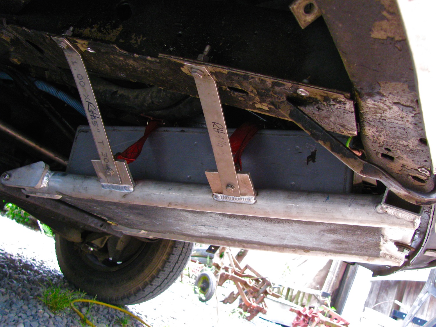
It took longer than making a baby but I finally have my big battery installed. I got this Northstar 200 AHr battery some time ago, I think I mentioned it in this blog post. The size and shape of the battery made it seem like it would fit easily under the rear seat but it just doesn’t ( without taking up more space than it needs, if that makes sense). I toyed with the idea, and went as far as making brackets, of mounting it up under the van between the door sill and frame rail but no, that didn’t look right. So I settled upon the admittedly dubious spot of where the spare tire sits. A couple of problems with this placement. Number one is that I now have to find a spot for the spare tire. Ah but what about my much talked about swing away spare tire carrier? More on that at the end of the post. The other dubious characteristic of this battery location is that it places 128 lbs forward of the front wheels. I’m a little worried that it might make a difference in how the van negotiates dips and ditches in logging roads. Skipping a head a bit, I have had the battery installed for a week and I really don’t notice any driving different on paved roads. I made a carrier for the battery quite a while back, crikey, it was a year ago, since then I welded in some locating brackets that the battery fits into, and some tabs on the side tubes for supporting brackets. The brackets are made from 1X1/8″ stainless and I bent them to fit to the van frame rails. They are secured to the frame rails by 5/16″ stainless bolts that I will someday change to 8 mm. The bracket to the tab connection is done with 1/4-20 bolts and instead of nuts I used stainless ring nuts. The rings are to secure nylon straps that cross the battery and hold it very securely to the tray. Ok, some pics of it installed. First pic taken from driver’s side, one stainless bracket not fastened. Gives you the general idea of how the battery lies. 
And on the passenger side. You can probably make out the red nylon hold down straps going up over the battery.
.
I had thought of making aluminum side splash plates but I was dissuaded by the changing angles and company curves needed so I used some scavenged treadmill material. I installed 1/4-20 riv nuts in the existing holes in the van frame and bolted the treadmill material.
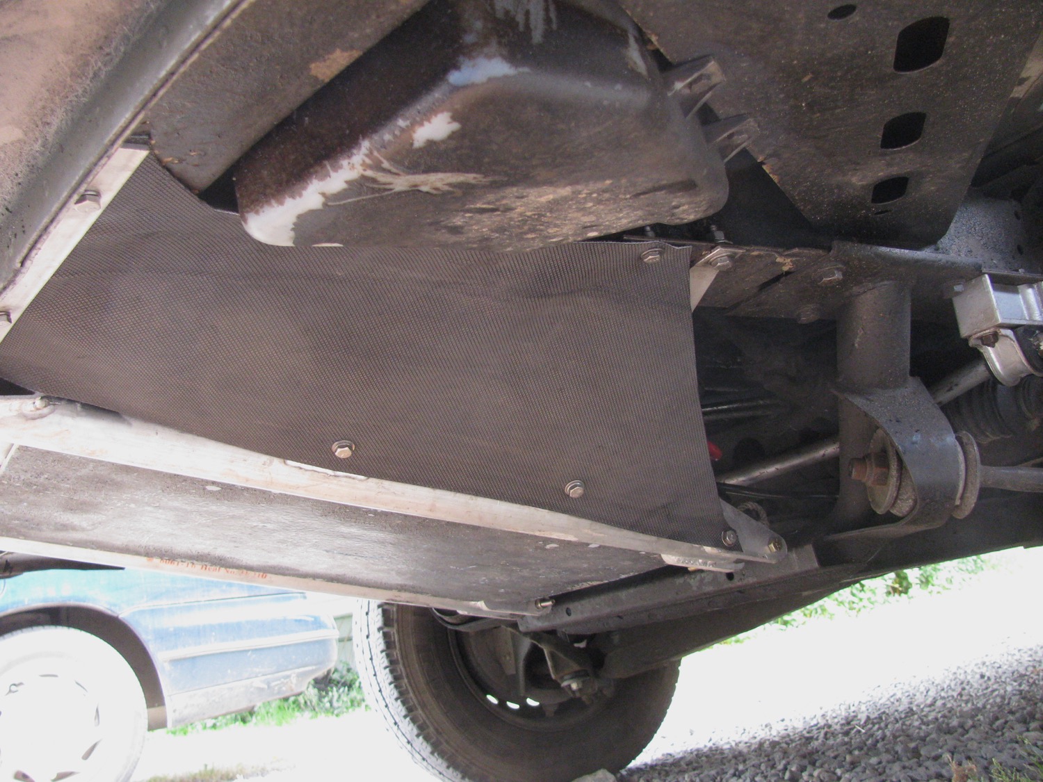
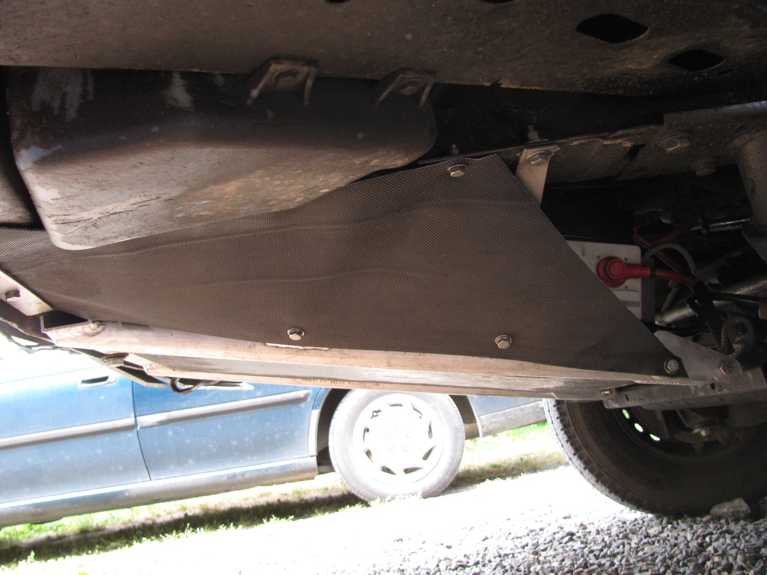
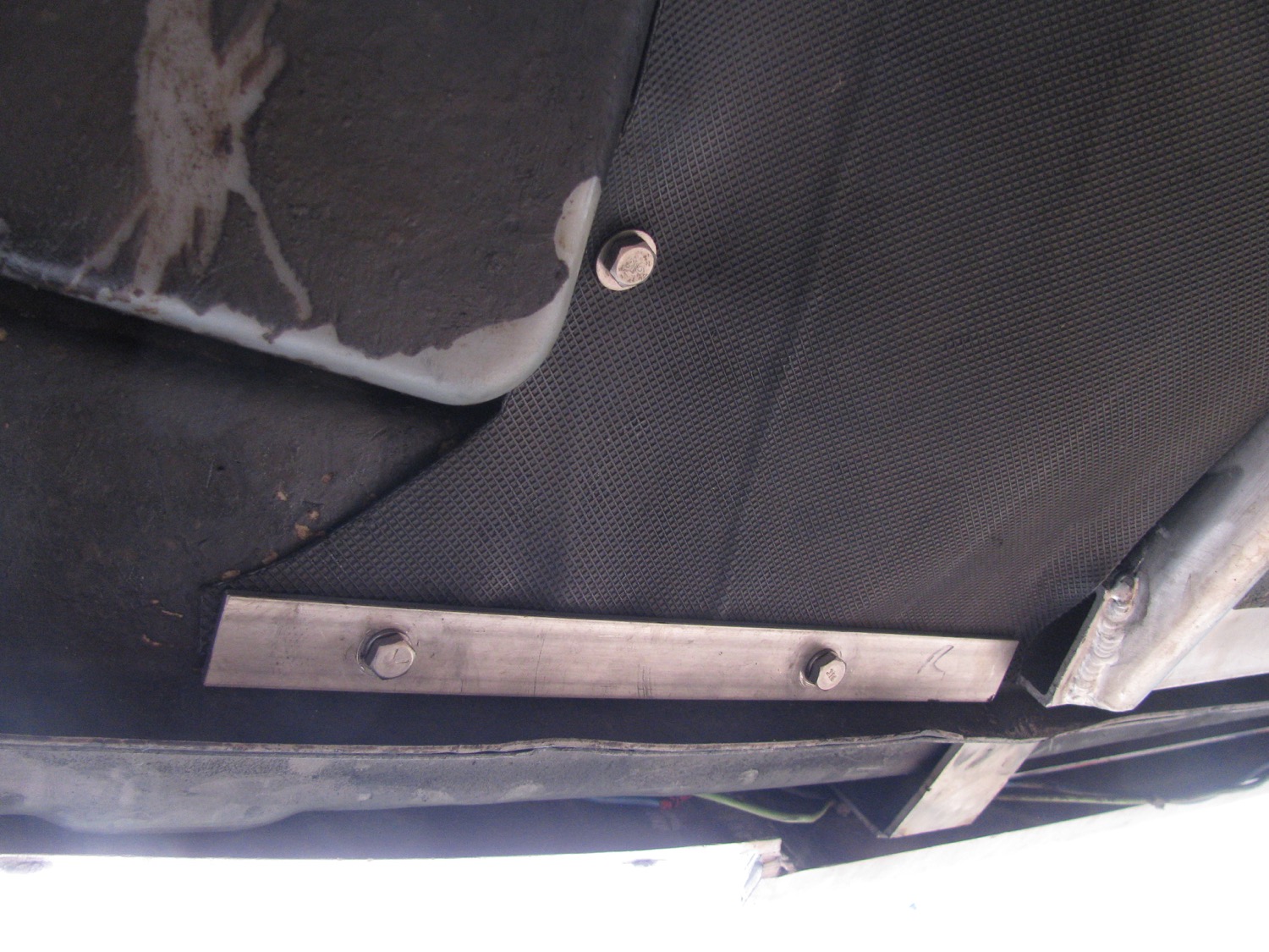
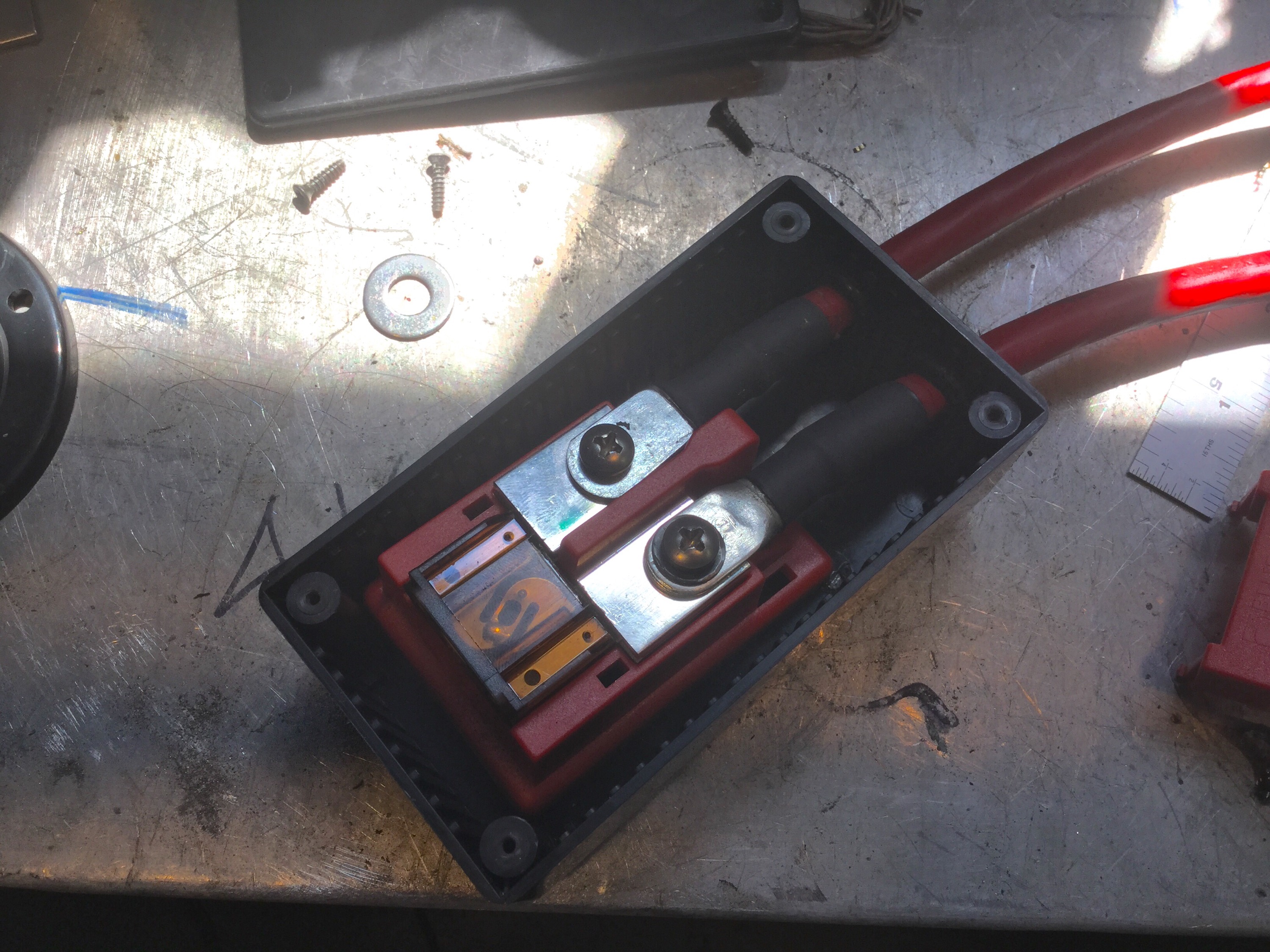
It’s not great but it’s not bad. It’s just there to reduce water splashing on the battery. Not shown in the pic are tubes leading from the battery vent up over the battery and on up to behind the front grill. When I did that I was thinking I was clever, I thought that leading the vents up high would prevent water getting into the battery if I happened to go through a deep puddle. But I found out later that the battery vents have a valve in them to prevent water ingress. A note on the wiring. I ran a short length of 4 gauge wire from the negative terminal back to the bolt holding on the transverse member supporting the front differential. On the positive terminal a short length of 4 gauge comes off the terminal and up into a black box (attached by Velcro) on top of the battery. In that box is a Blue Seas Maxi Fuse block, with a 70 A fuse.
Update: in the comments Marius wondered about battery cold weather performance. Here is a graph I found in one of Northstar’s documents .


 Then out of the box and through some plastic sheathing and a sealed bulkhead fitting into the battery compartment behind/under the driver’s seat. Then it continues on to connect with my Blue Seas ACR. I’ll write more on that when I tidy up the wiring, I’m going to change the auxiliary power distribution layout there. I was surprised and pleased to discover that when all is bolted up tight the stainless straps from the tray to the frame seem to support the entire weight of the battery. The bolts at the rear, where the tray hinges on, have no weight on them. So that pretty well sums up the installs the battery. As mentioned I will post more on the auxiliary power distribution set up when I finally fix the positions of the various components. So… The spare tire, where does it go? It’s time for a confession, I couldn’t get my swing away tire carrier to work the way I wanted to. I’m not going to explain all the things I tried, and I did try a lot of things. But I could not get happy with the rigidity of the set up. The tire vibrated in the carrier when I smacked it with my hand. It bugged me no end. I finally lost my patience and removed it, cut out the hinge from the bumper and welded the bumper back together and painted it. I’m going to make a hatch mounted tire carrier, don’t laugh… Yet. In the meantime I’ve pulled my old Paulchen rack out and I have the tire bolted on that.

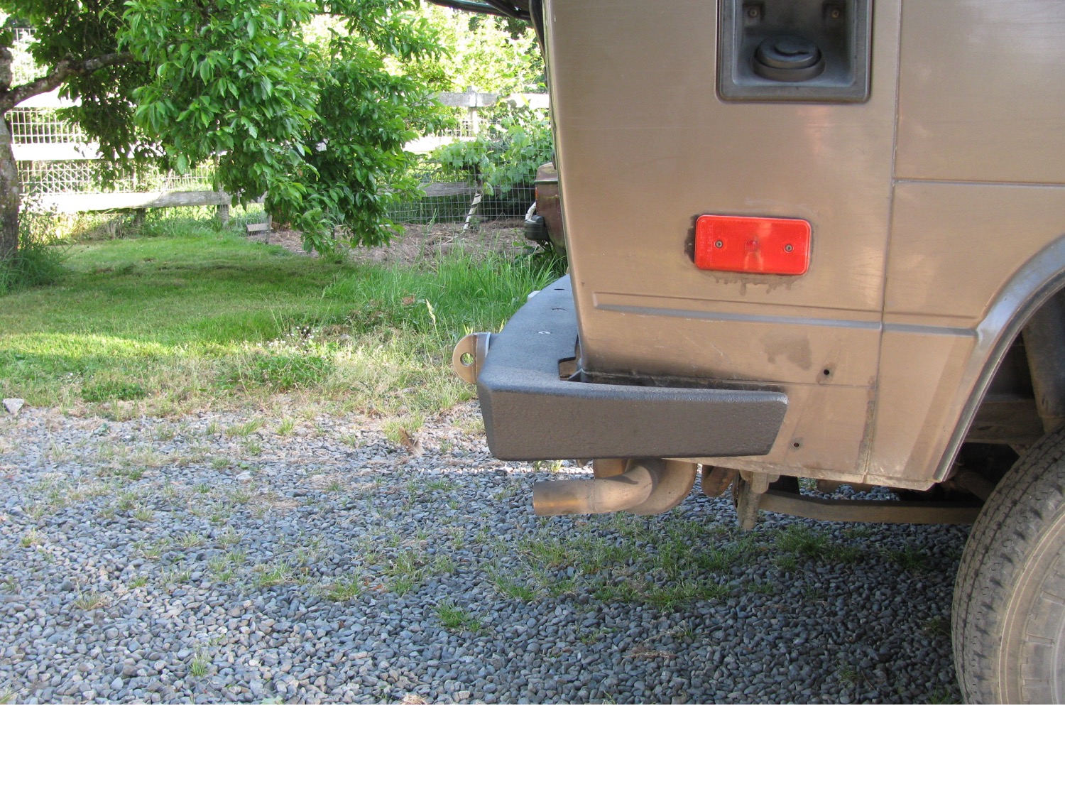
And the bumper… well its ok, but I’m not ecstatic about how far the end caps stick out, oh well maybe I can say it provides better side protection and its Mk I. And i still have to paint the tow loops and the receiver hitch.


Vanagon – kinda crazy sway bar mod to help install homemade drop links
Posted by albell in syncro, syncro specific repairs, vanagon, vanagon mods on April 25, 2015
This value of this modification to the sway bar is debatable. But hey, don’t let fear and good judgement hold you back from having a bit of fun. And god knows I’m not going to sit here and tell you this is an original idea, I’m old enough to know that someone somewhere has done this before.
I didn’t look forward to installing the sway bar drop links with Whiteline polyU bushing. It can be a bit of a struggle getting the drop link onto the sway bar. Mind you, Chris at T3 Techiniques makes it look easy in his video. By the way, T3 Technique is a place to buy polyurethane bushings and other suspension parts.
http://www.youtube.com/watch?v=7oXY68F8Uwo
I had thought about the notion of cutting the knob end off the sway bar then drill and tap a hole so a thick washer could be attached to replace the knob. But I didn’t like that idea for a few reasons.
So what I did do was this, I welded a 3/8″ stainless steel bolt to the end of the sway bar. Well I should say sploodge welded the bolt on, not pretty.
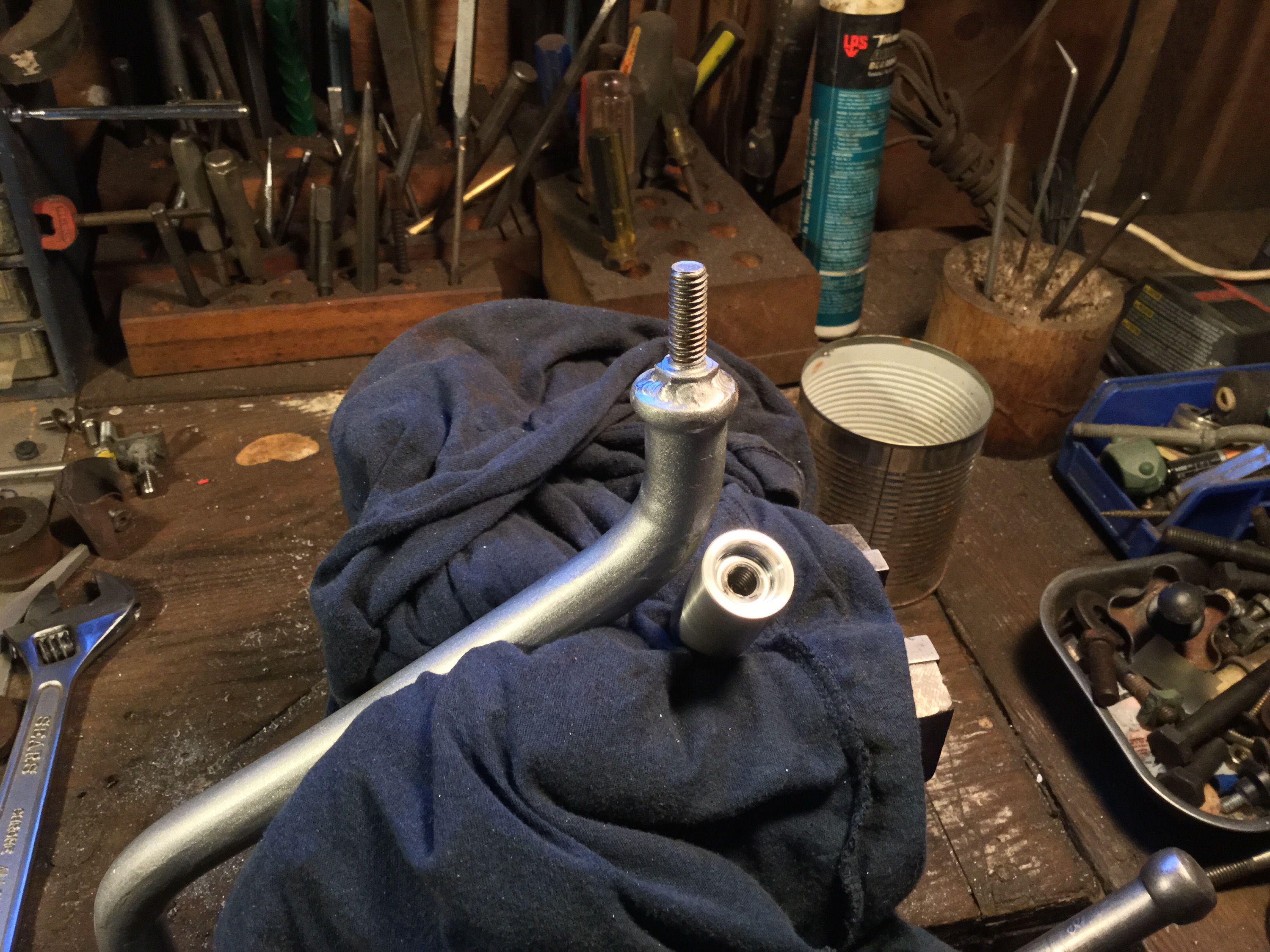
So what eh? Well now I made a bullet shaped tool, tapped for the 3/8″ bolt on the blunt end and tapped for 1/2 NC on the pointy end.

Some tubular spacers, lube, and a nut and the bushing ( already fully seated in the drop link by squeezing the two together in a vise) and hey presto, the bushing and link can be easily pushed on to the sway bar. Hey don’t rely on this pic for correct orientation of the sway bar bend to the sway bar, I was just doing a test run and didn’t take care. I did get it right in the final assembly… I think 🙂


i made a Delrin cap to fit over the exposed bolt. Tidies things up and may help to prevent the drop link coming off the end of the sway bar. This has happend with the softer urethane Powerflex bushings, maybe not as likely with the harder Whiteline bushings I have used, but hey, it’s another justification for this mod.


And of course I scraped the heck out of the paint on the sway bar installing it on the van.
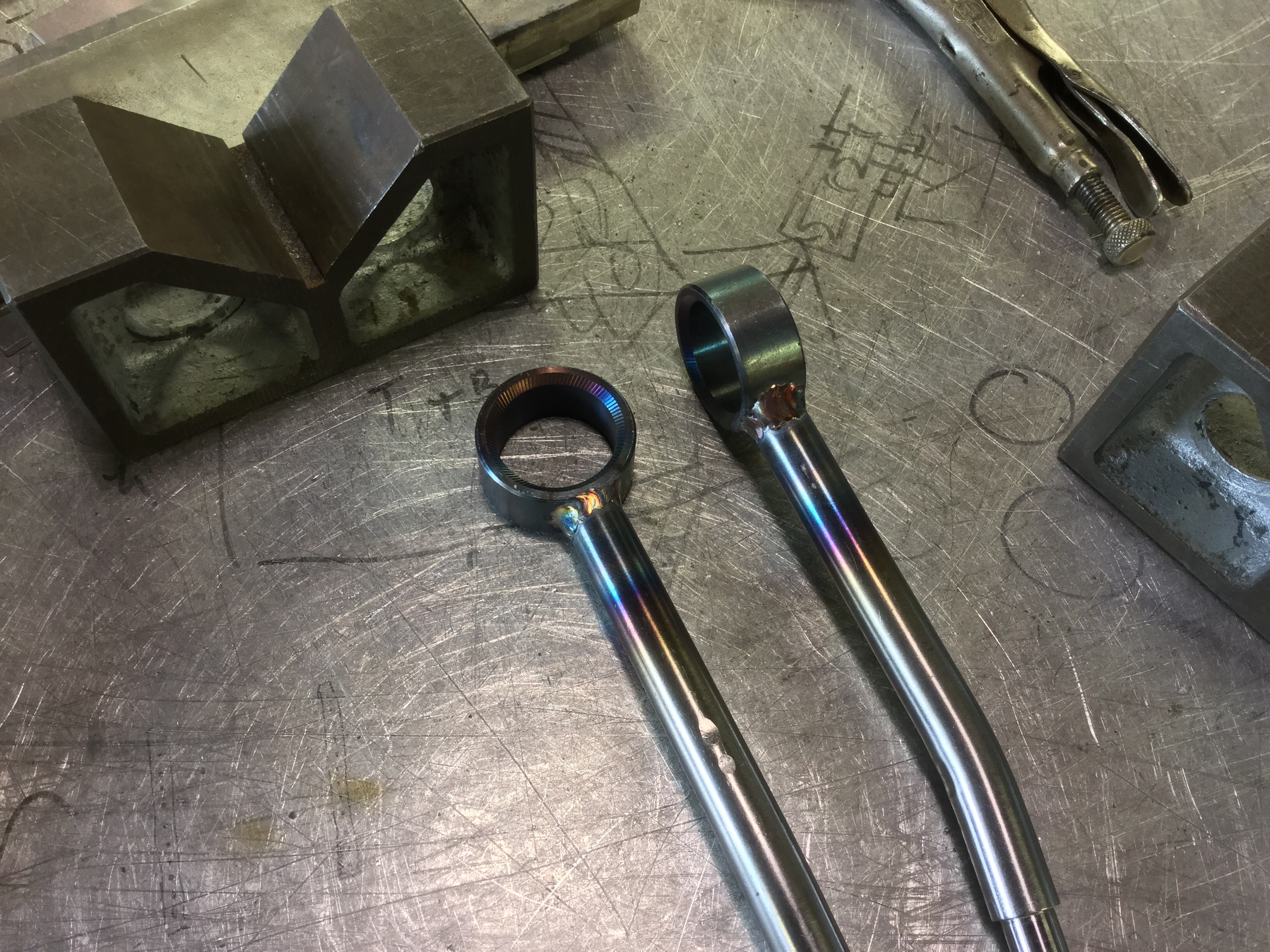
 I guess I should show hey finished drop links. I had machined them a while back, 3/4″ (19 mm) stainless rod and heavy walled ( sorry I forget the wall thickness) tubing which had ID of 1 1/2″ (38mm) very close to to the stock link. Threaded the end M12X1.5, and a section approximately 17mm in diameter where it passes through the drop link bushings. No spacer in this set up, we’ll see how that works out, but is not an original idea.
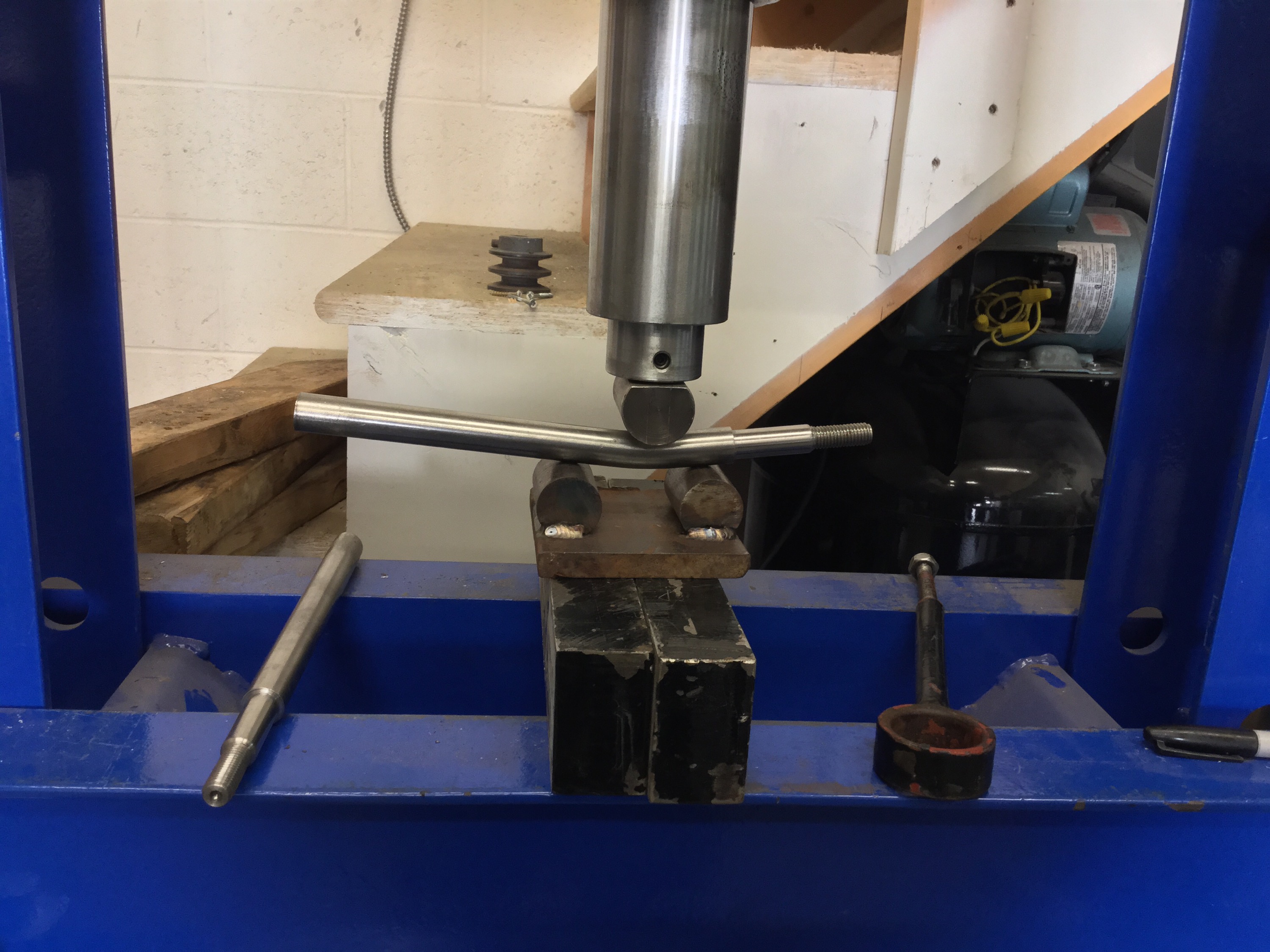
I bent them on a friend’s press using a quickly made set up that does leave some dimples in the bar. I think I took about 8 tons of force to bend them. I was shooting for 4 degree bend, but I went a degree or so more. I don’t think that will be a problem.
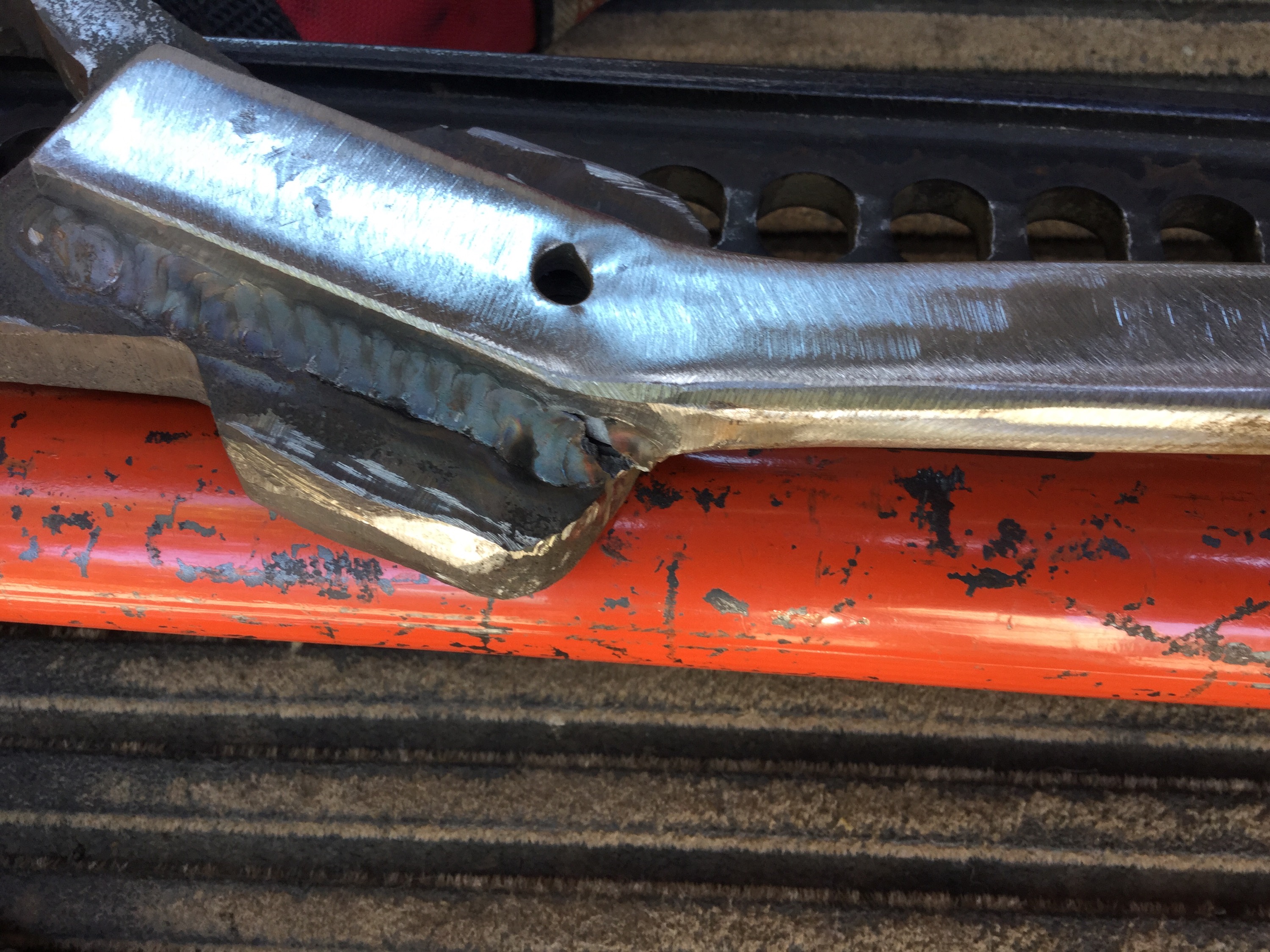
I cut them to length and ground a chisel point on the end. One root pass, then two straddling passes of weld, then I washed over with the torch. I got a bit of under cut on the rod, I could have done better but it will be strong enough. Notice the pattern on the ring portion, patented “Chattr-Mastr” finish on the bevel.


I used the cup washers I made a while back, but welded on a smaller diameter flat washer to the should of the drop link as I was worried that the enlarged hole of the cup washer would get pressed over the shoulder under hard use in the van. I think you might spot that washer in the pic of the sway bar install. I’m happy with these drop links, maybe not in the same league as Burley Motorsport’s, but ok for an amateur.
And another thing, with the bolt welded to the bar it is possible to make some little adapter so one could use a puller to remove the drop link from the bar easily. Ok, that’s a pretty weak advantage of this modification but I’m trying to find other reasons to account for the time and effort.
Vanagon – frustrating sidetrack
Posted by albell in vanagon, vanagon mods on April 19, 2015
Had a really frustrating week, seemed as though everything I touched went sideways. Most annoying was trying to eliminate vibrations in my swing away tire carrier. The latch pulls the swing away tight to the bumper assembly and I am pleased with how that finally worked out, but I don’t like the small amplitude vibration I get on the holder when the tire is attached. I think I am going to weld on a stiffening gusset to the upright and see if that will stiffen things up.
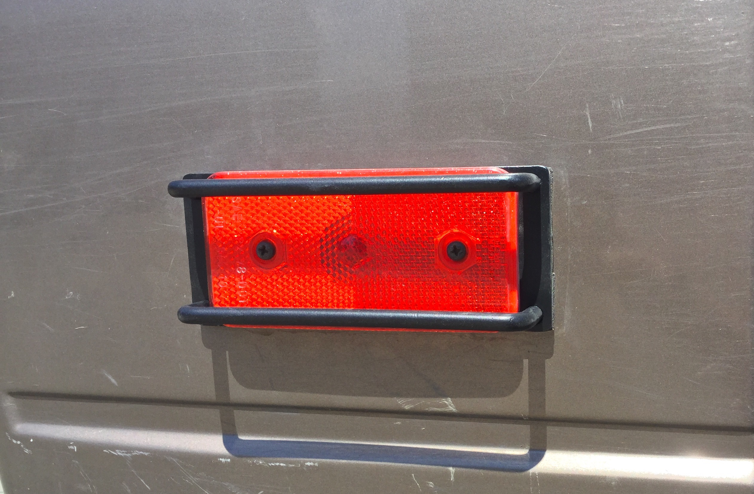
I bought a cheap rod bender from Princess Auto, this one here. It was on sale for 79 bucks. It works ok for what it is, and I thought instead of just bending random shapes while I try it out I would actually make something “useful”.
Well, I tried making a tail light protector and I soon realized that you REALLY NEED TO MAKE A JIG!
I’m showing you the result as a warning, think things out before you start merrily bending stock 🙂

The the tricky part was locating the little stand-offs accurately on the screw holes in the tail light. It’s obvious that the tail light is thicker at the top, but it also has subtle curves laterally and I was trying to match those curves and that made placing the little hollow studs for the mounting screws maddeningly difficult. You can see the nasty welds at those studs, result of tacking, checking, cutting, tacking, checking, cutting…
You really do need a jig.
And I think the guard would look a whole lot better if the vertical cross wires were not welded on top of the horizontal wire but welded to the middle of the section. I’m not going to try another until I make a jig, but even assuming I pop one off without pulling out my hair, these would be fussy and expensive Vanagon jewellery.
Vanagon – attempts at making cup washers
Posted by albell in vanagon, vanagon mods on April 6, 2015
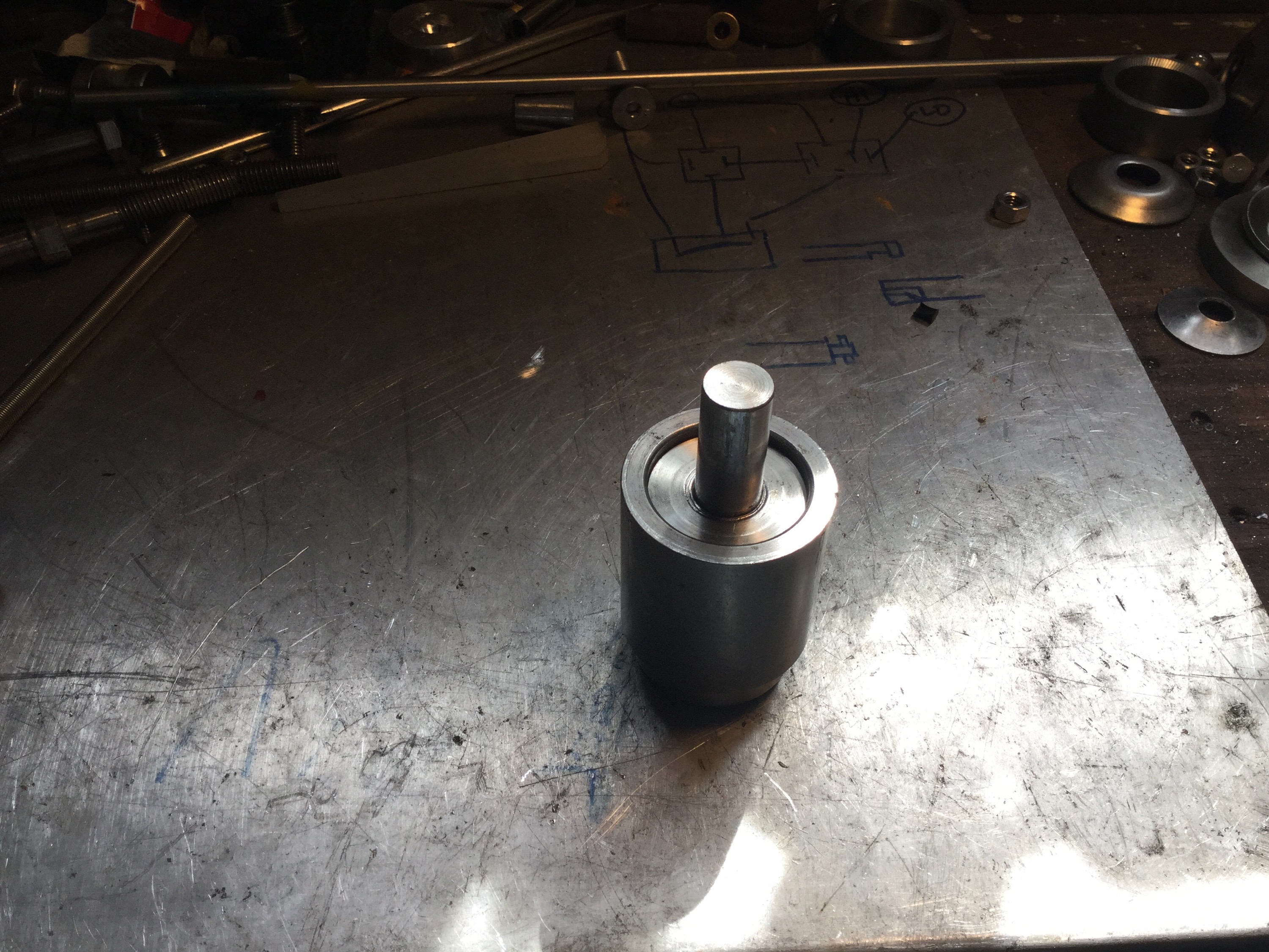
Not quite an unqualified success, but not a complete failure, I’ll settle for that. One of my sway bar drop links broke again and instead of the kind of repair I did previously , I decided to make new ones from stainless and beefier stock. I’ll detail that build when I have them welded up and bent. But I needed new cup washers and rather than buy them ( aren’t they around 13 bucks each?) I thought I’d have a go at making some from 2″ stainless washers. Here are my results.
First I tried pressing a ball bearing into the washer with a socket as a back up. You see on this test washer that it doesn’t make a good profile.

And on the 2″ washer.

So then I tried a different approach. Pretty self explanatory.


Useda friend’s press,applied between 10 and 15 tons of pressure. I also tried both ends of the male die, but the result wasn’t that great.
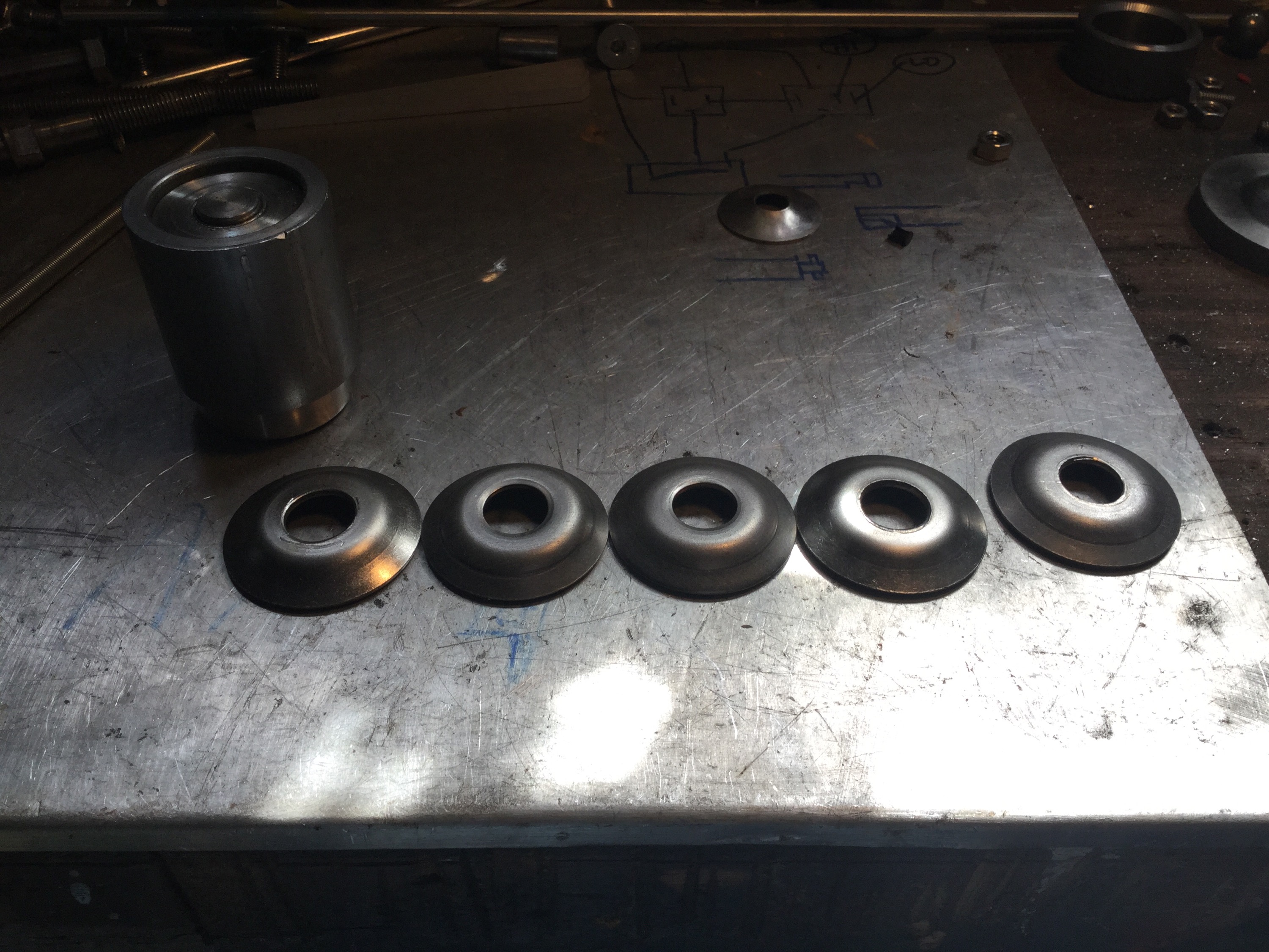

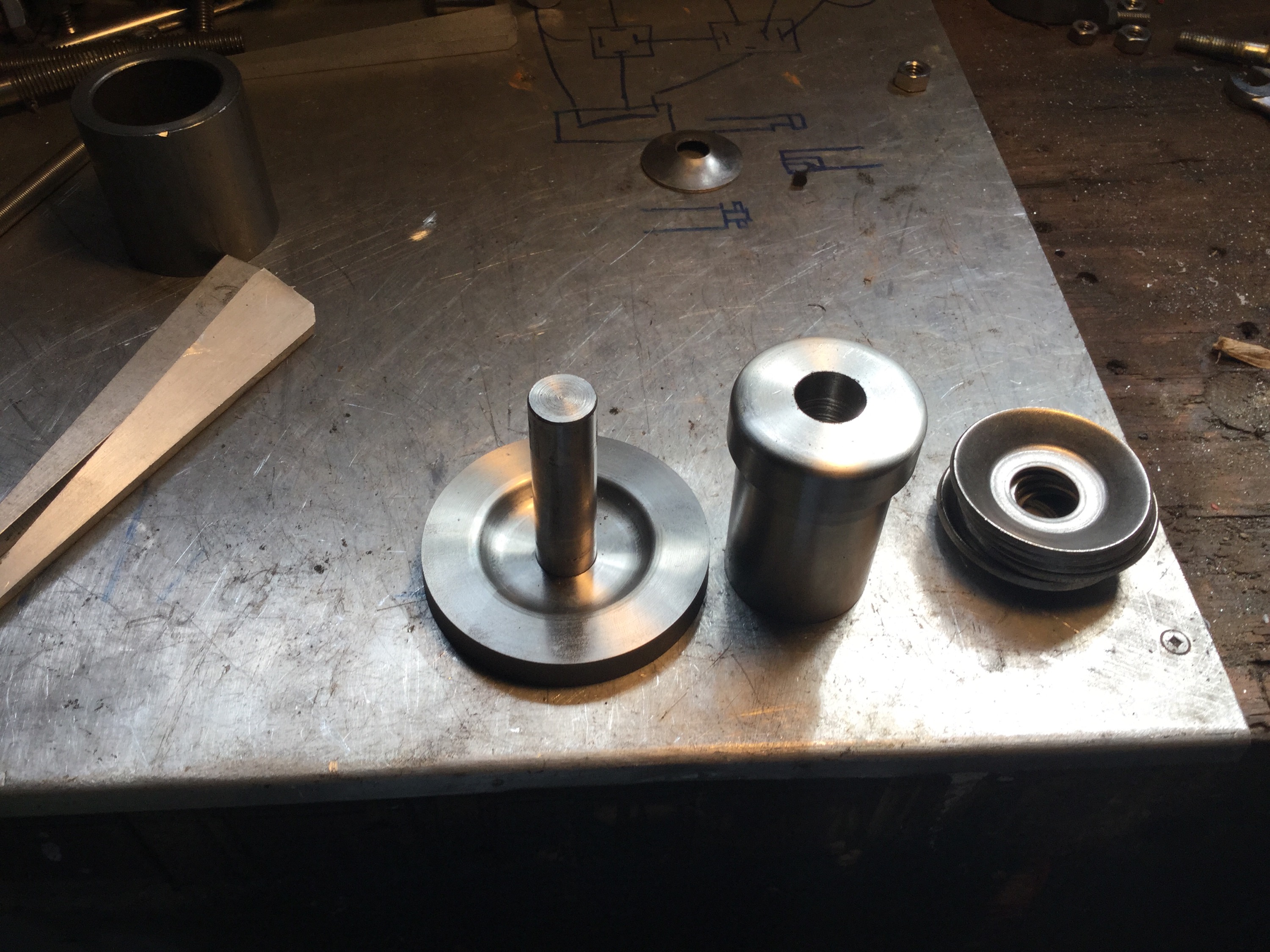
So I tried again. A quickly made female die with a rough profile of the shape I wanted, and a not very close match on the male.
 .
. 
Back to the press and…
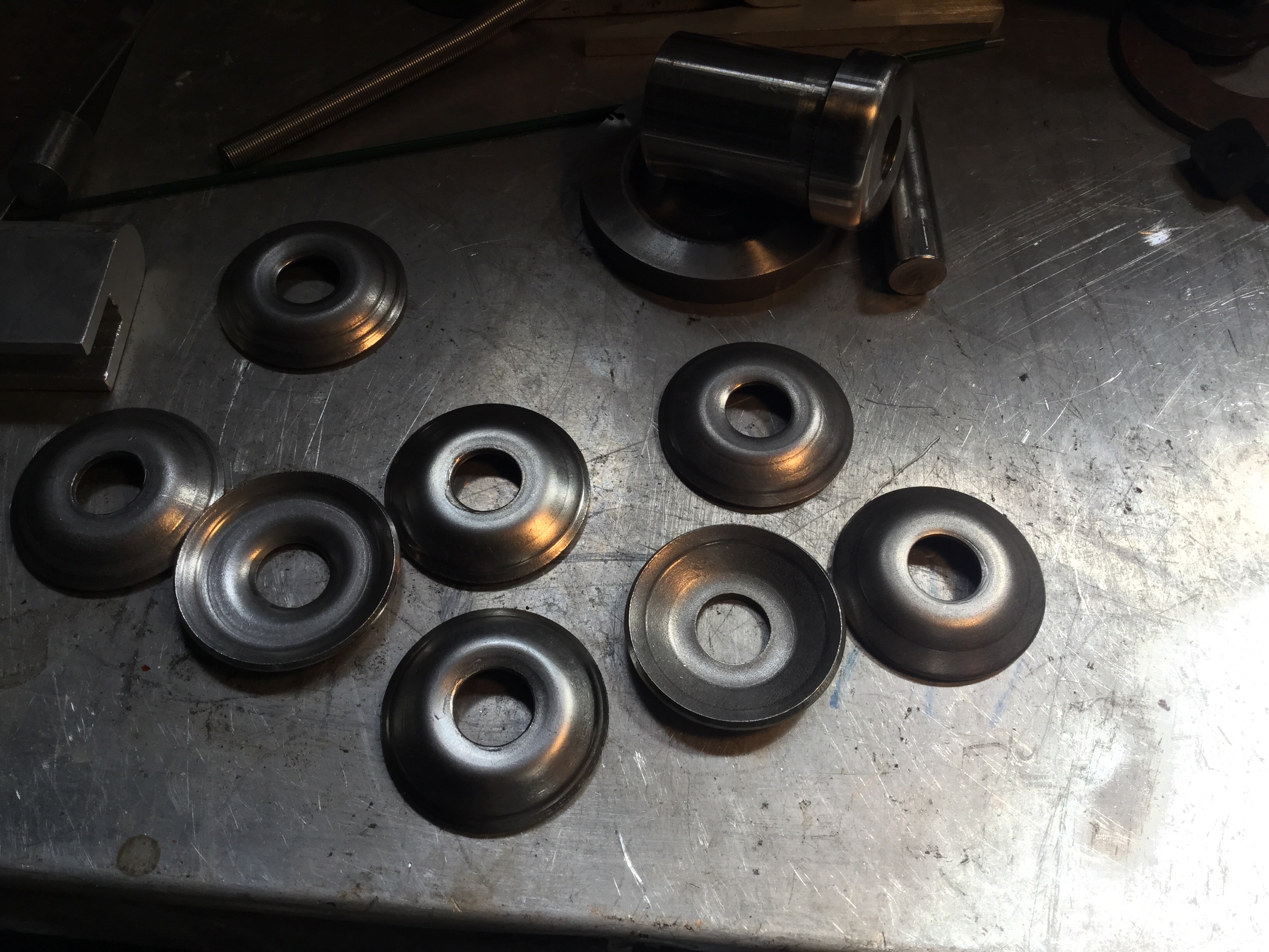
Well not great either, but I’m going to stop. I’d didnt do any research on how one should make dies for this purpose, i bet I am missing something quite obvious
The end of my unfinished drop link.

And with polyurethane bushings and the new washers. Hey, note that I have ground a rough radius on the inboard side of the bushings. This helps them fit into the recess on the lower control arm. No’ they aren’t quite that same as the stock washers. The stock washers have a larger un curved area and turn up more quickly at the edges. But I figure when the bushings are compressed when installed, the washers will make enough contact and still allow some lateral movement of the drop link.

Vanagon – rear bumper, swing away tire carrier latch
Posted by albell in vanagon, vanagon mods on April 3, 2015
As I’m now using geological time scale in describing the progress on my rear bumper build, this latest update comes very quickly after the back up light install.
I needed to make a latch that would secure the swing away carrier tightly, but yet be reasonable easy and quick to use. I tried four designs, my designs, conclusively crappy designs. This, my fifth attempt would be my last, next stop would be buying a de staco type draw latch.
I still had the Delrin cone and socket arrangement that was for my first design. The cone and socket does work well to locate the arm to the steel back stop that is welded to the bumper subframe. So I kept that and made a draw latch.
Reinventing the wheel.
But I learned a bit while doing it. It’s interesting how the effective lever arm changes on an offset hole draw mechanism like this. The pivot points, effective distance, changes from about 3/4″ when draw hole ninety degrees from the pivot to zero when draw pivot are inline. This gives great mechanical advantage when closing the latch, and the over centre part helps keep the latch closed.
I occurs to me that describing all this is a bit of a mug’s game. Maybe some of you think that I should have bought a latch and be done with it, a very valid point. Some of you are probably not very interested in some damn latch – just show the finished project, an equally valid point. And some might think I’m boasting about making the darned thing. It’s that last suggestion that bothers me.
You could make the case that writing any kind of blog is a tad egotistical. But believe me, the best thing about writing this kind of blog is finding out that you might have helped or at least nudged someone in the right direction.
Ok, enough blether.
I made the handle from 1″ thick aluminum. Part of some offcuts from the water jet guy. Had a nice curve and I continued the curve ti make the working end. Drilled holes for the pivots, slotted the end for the fixed pIvot ( that attached to a little bracket that was made from some 1/8″ thick stainless, mounted to the carrier with 1/4-20 bolts, helicoil inserts in the carrier).
I turned and milled a bit of stainless to hold the bail ( the moving pivot) and the bail is a bit of 5/16″ stainless rod that I bent into a U shape and threaded the ends.
I used some 1/8″ stainless plate and 1/4″ rod to make the little catch on the backstop that hooks onto the bail.
I was worried that there wouldn’t be enough give in the mechanism, so I stuck in some hard rubber washers under the nuts on the bail. You can see them in the first two pics. I found that there was enough flex in the backstop latch that the washers weren’t needed.
Ok, the handle and fixed pivot.


And mounted on the bumper. 
See how I have to use some spacers to match the thIckness of the cone and socket bases to give the upright of the carrier a bigger surface to pull against? I’ll try and make a nicer version of the spacers, maybe one piece.
I have to make a plug for that hole. Also a fair bit of grinding and sanding to be done before painting. But hey, I’m making some headway.
Oh, and I have yet to weld on some sort of tab thing on the end of the handle so I can pin it to that curved tube as a safety or even a lock.
Vanagon – carpaccio flooring
Posted by albell in vanagon mods on March 26, 2015
My old floor, shown here in this post, was really getting a bit beat up. It lasted close to 15 years taking quite a bit of abuse so I can’t complain. When I put that floor in way back when, I had it in mind to face it with cork and I still hope to do a cork floor someday, but I found something at work that tempted me.
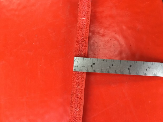
The stuff came to us protecting some stainless steel weather bouys. Approximately 3/4″ thick, the material is closed cell foam and quite stiff. I’m thinking its polyethylene, but it sure isn’t soft. It is very tough, the surface seems resistant to catching sharp edges. It also has strands of some sort of fibre embedded, to reduce tearing I guess.
I cut it up into strips and installed between the seat rails.
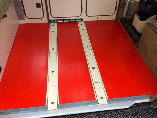
Pretty bright eh? But most of the time I have some of those interlocking foam pads on the floor.

And all covered by an inexpensive bit of carpet from Canadian Tire.

Here is a close up of a scrap of the foam.
You know, having that bright colour on the floor makes me want to have a brighter coloured throw rug.
St. Paul with sword and Bentley.
Vanagon – the ongoing rear bumper build – back up lights
Posted by albell in vanagon mods on March 25, 2015
It’s getting embarrassing, but I still haven’t finished the job. What is stalling me is a latch to hold the swing away tire carrier very tight against the back stop. I’ve made a few latches but none have combined the two key features of holding it tight and being very easy to use. The rest of the bumper is finished but still unpainted. Recently i added back up lights to it.
For the last year I’ve had the bumper installed and a 4″ halogen aux light bolted to the top for a back up light. I put a 100W H3 bulb in it and yes, it does light things up. A bit obnoxious in parking lots, but really useful out in the bush. But that was just a temporary thing, I now have my real back up lights.
They are a pair of 10W LED units bought from Deal Extreme. Here is the link to the product page. They are pretty nicely made little units. I cut a couple of holes in the bumper, welded on some mounting brackets on the inside and installed them.
First the before shot. Note that in this shot I have the stock incandescent bulb in the right taillight, a new LED bulb in the left taillight.

The aux light covered up, showing the improvement in lighting the LED bulb in stock taillight.

Ok, aux light removed, internal mounted LEDs installed. Daylight pic.
And night shot.

I like them, they work well. I am probably going to wire them to a spare switch I have up front so I can disable them in the city.
Vanagon – rear table socket
Posted by albell in vanagon, vanagon mods on March 24, 2015
Ok, this is not the most astounding modification of a westy, but it is a nice little touch. I was looking at the hole in the cabinet where the rear table leg goes in and I thought that it should have some sort of trim on it. I had the distinct idea that later westies did have trim there, but I found out later that my friend’s ’91 westy doesn’t. So I have no idea how the thought got into my addled brain.
I made a trim ring from some black Delrin.

Ok, that’s all well and good, but fellow Vanagon mailing list member Stuart wondered if I could make a leaking off plug for the hole as he doesn’t use the rear table. I had a little bit of some sort of South American hardwood that I had been hoarding for, I can’t belive it, 30 years, and it seemed like the right stuff to use for the plug. Stuart thinks it’s Cocobolo, and it might well be.

Vanagon – Westy rear seat head rest sockets
Posted by albell in vanagon mods on March 24, 2015
Fellow Vanagon mailing list member Stuart M asked me to make some sockets to affix to the westy rear seat so that the stock plastic insets could be fitted and then spread rests installed. I think there was a factory part made to do this, and I believe it involved cutting out a little of the plywood in the seat back. Also , some folk made steel tube versions of what I did. I believe ther is a Samba thread on that, yes there is, it’s here. As I work mostly with aluminum, I made a couple of pairs out that wonderful metal 🙂
I don’t know if you can make it out, but the slots on the top of the tube are of different width. That’s because the plastic socket has two rails down each side and the rails are different width. And i suppose its obvious that with this hack you have to sand off most of the plastic rails leaving just a little bit to engage the slots.


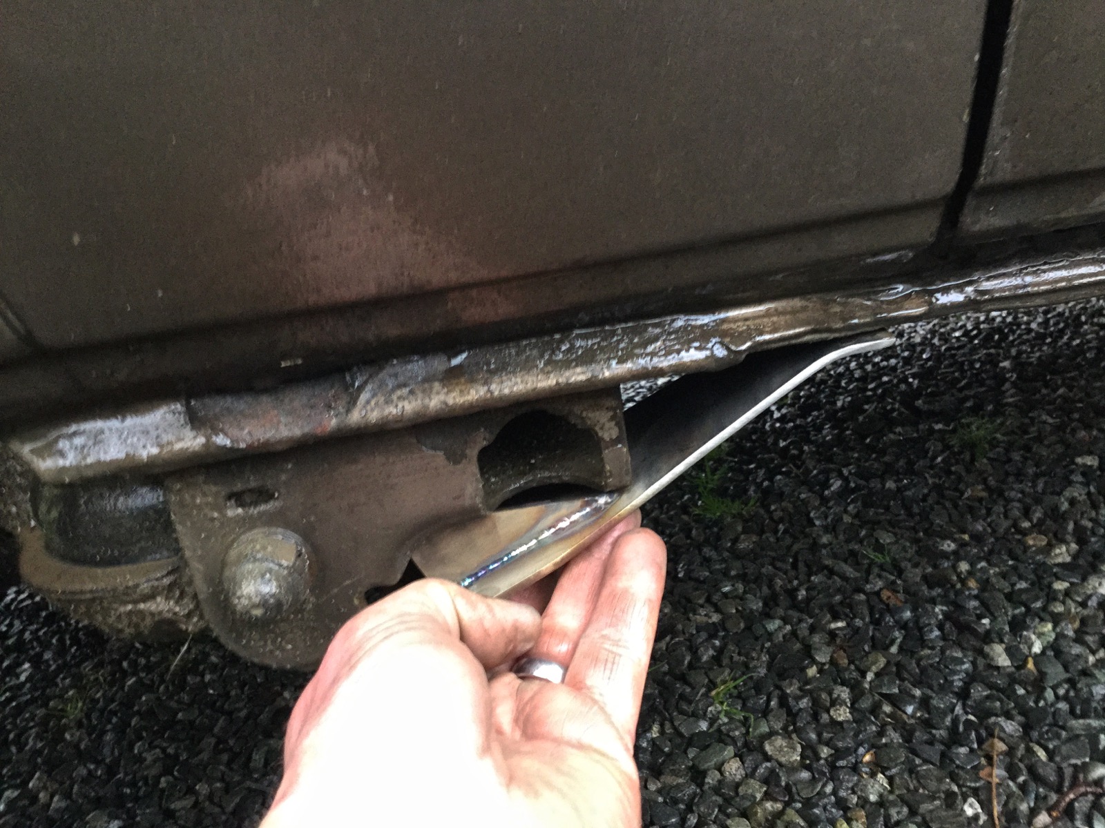
Vanagon – rear jack point/trailing arm protector
Posted by albell in vanagon mods on March 24, 2015
I’ve had a copy of the VW publication “Journeys under difficult conditions” since the early nineties. It’s a guide to modifications and tips for vanagon and LT owners who are planning on taking some rough trips. You get the impression that it is mostly centred on trips to North Africa, but the body protection modifications are pretty universal.
I only have a photocopy of the document, but I think it has been uploaded elsewhere. Maybe syncro.org.
Anyway, I finally made something from the plans. It’s a simple little thing meant to protect the rear jack points and trialling arm outer mount from damage. I made it from 316 stainless and just cut the stock with an angle grinder and zip disk. I made the bend in a vise, you can see the bend is not as crisp as it would be if i had used a press brake. But it fits up fine.


Vanagon – quick peek at my front bumper build
Posted by albell in vanagon mods on March 24, 2015
i still haven’t completed my rear bumper, I have it installed but unpainted and struggling with a good latch for the swing away tire carrier. I’ve tried a few ideas, but not happy with any of them.
But that hasn’t stopped me from starting a front bumper. Here is a picture when I was deciding on hole placement for auxiliary light mount. Btw, made from 1/4″ 6061 aluminum, that flat section in the middle is 3/4″ thick. As much as it looks like it, the flat section is not for a European style license plate but rather to mate with a replacement for the stock tire carrier – the forward end of the carrier will curve up in front of the bumper. Link to that carrier here.

Vanagon – quick throttle body re-bush
Posted by albell in vanagon, vanagon mods on September 13, 2014
A few years ago i tried re-bushing a spare throttle body using Delrin as the bushing material. I couldn’t get the throttle action smooth, it seemed as if the Delrin had a stiction property that I just couldn’t over come either by sizing the bushing or lubricating. So I laid the project aside and forgot about it.
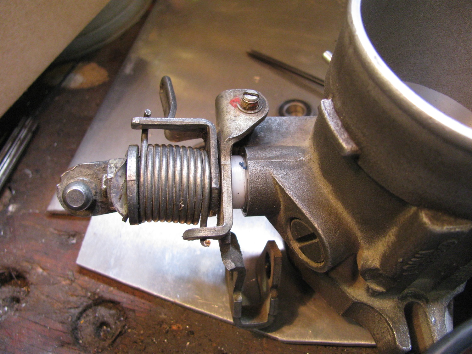
Then this last summer I noticed some play in the shaft of the throttle body installed in the van. There was enough play to make adjustment of the throttle position switch very fussy. So i though back on my previous experiment and I thought I’d try making bushings again, but this time out of HDPE.
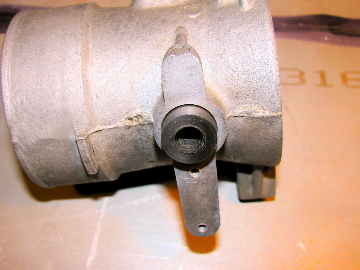
First let’s go back to my spare throttle body, the one I re-bushed with Delrin. I have a blog post here showing it before I started screwing around. I even went as far as cleaning up the wear marks in the bore and making a new butterfly plate to compensate for the now enlarged bore.


See the Delrin bushing?

And on the other side, the throttle position switch side.
My daily driver one on the left, the re-furbed one on the right.

Not the larger cam on the one on the left. This is the newer, revised throttle position switch system.

It appears like a lot of space around the butterfly, but it really isn’t that bad. I can’t recall the gap size (I measure with wire).

It kinda looked ok to me.

The dried up seal on one side.

And the other.

Wear in the bore from the butterfly.

I decided to leave bore and the butterfly untouched. I chucked up a hunk of polyE and turned and reamed a couple of bushings.

Recessed on the throttle position switch side.Why? because the switch plate has little locating tabs that fit into the hole.


Pretty well flush on the other side.

Gosh, i can’t recall for sure the butterfly shaft diameter, maybe it was 8 mm, yeah I think so. I do have an 8mm reamer. Anyhow, I did think about bearings instead of bushings. But the bearings I had on hand had a larger OD and that would have meant taking the throttle body to work to use the milling machine; tedious set up and then a boring head.

Assembled. I have to say the action of the butterfly is smooth as silk, much better than the Delrin. Come to think about, I wonder if I reamed the bushings the last time?
The throttle position switch now is easier to set, there is no wobble in the butterfly shaft.
Vanagon – front suspension bushing work
Posted by albell in syncro specific repairs, vanagon, vanagon mods on September 12, 2014
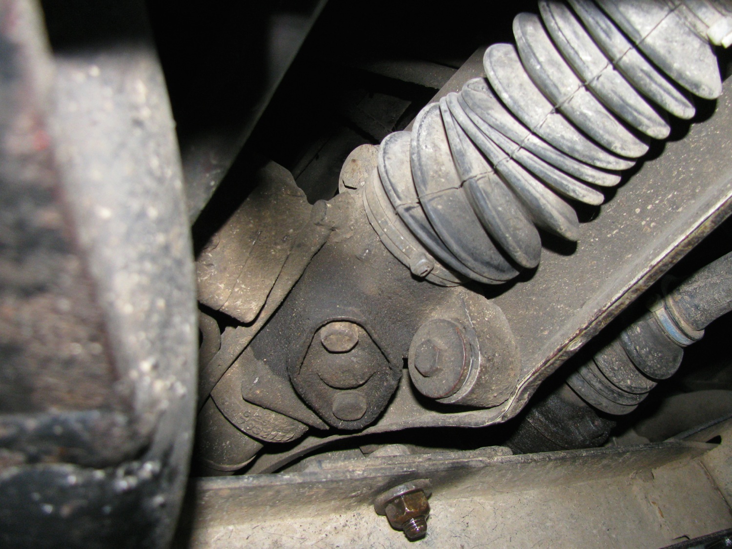
About a month ago i replaced a few bushings on the front suspension of my ’86 syncro. They were they sway bar to body bushings, the sway bar drop link to control arm bushings, and the steering rack bushings. I replaced them with Whiteline polyurethane bushing from Chris at T3 Technique. I can whole heartedly endorse Chris for his great customer service and products.
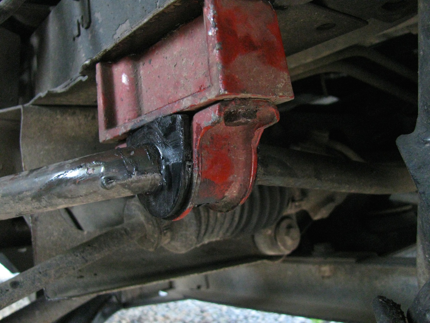
So first the easiest, the sway bar to body mount bushings. Here is a pic of the one of the original rubber bushings.
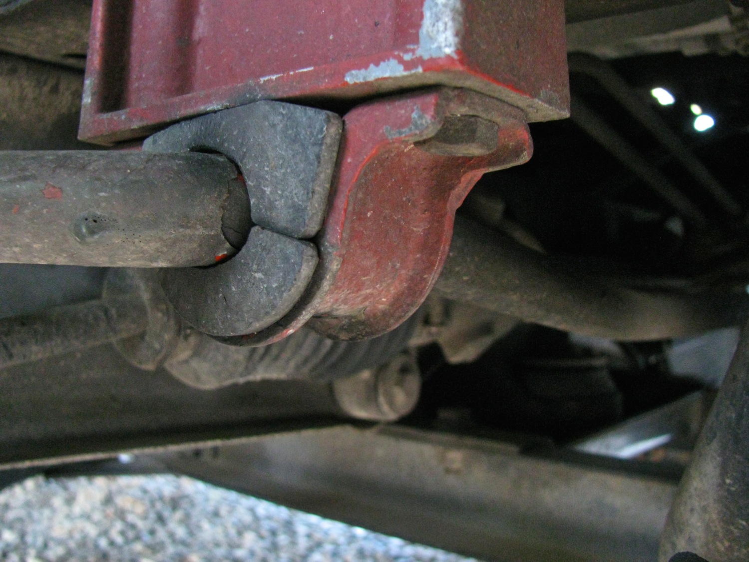
A couple of 13 mm head nuts and bolts and the mounting bracket comes off. Note the spacer used in the syncro bracket.
New bushing comes in pairs, and with a sachet of grease. Grease is important in polyU bushings. They do have a reputation that they squeak, so you must grease them up with s low wash out grease. T3 techniques sells a couple of greases, and I bought one of them, Accrolube. I didn’t know when i ordered that the Whiteline bushing come with their own grease. So you might see in the pics that i have used both the black grease from Whiteline, and the blue Accrolube. Note that the Whiteline package has instructions on where to apply the grease, important for bushings that undergo twisting motions.

Pretty easy install.
Next up are the drop link end bushings. You can read all about what I had done to the drop links a few years ago here and here
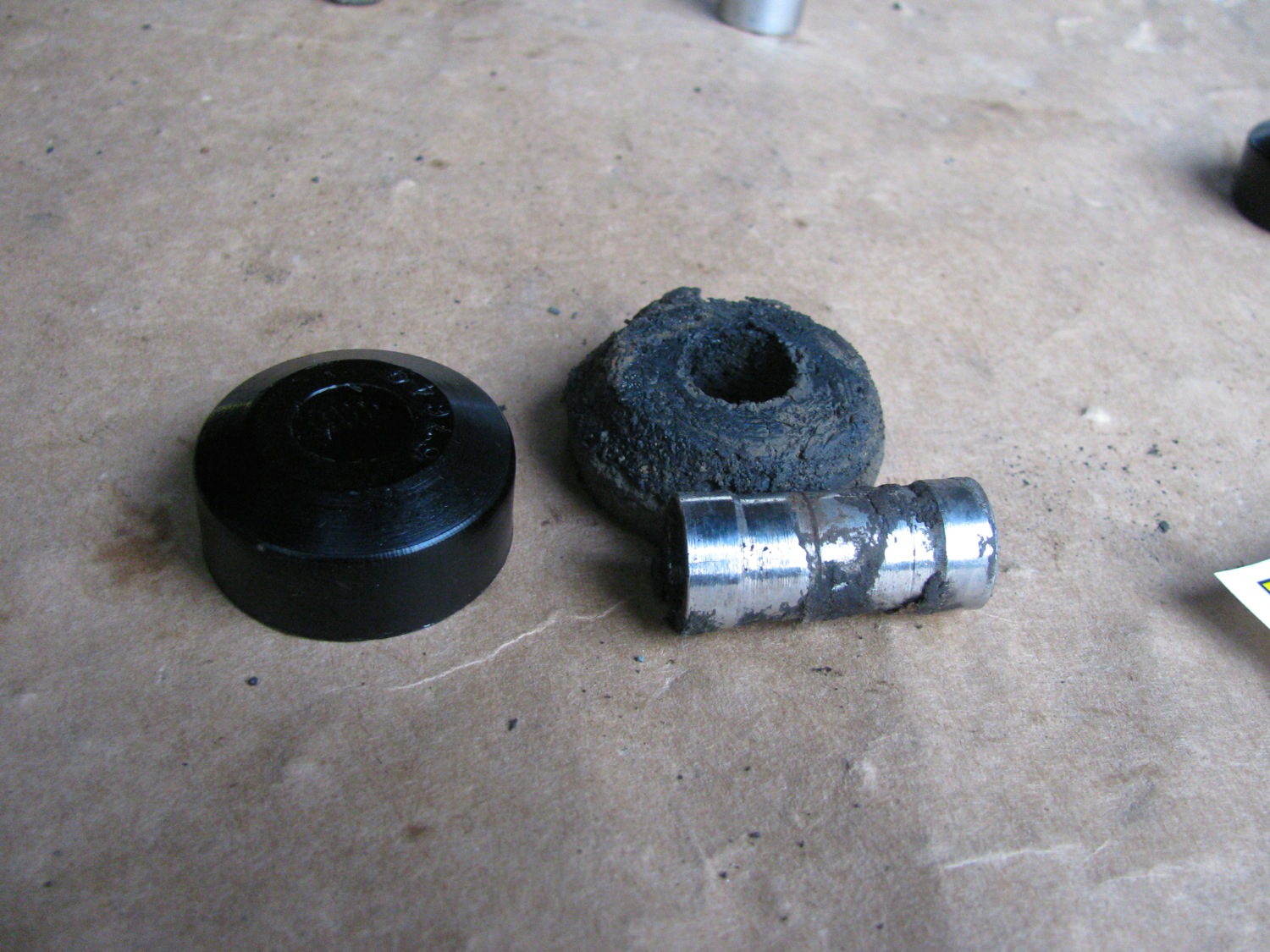
So far all the work has been done with van on the ground, but after I removed the nut at the end of the drop link I jacked the van up so that the drop link pulled up and out of the lower control arm. Be careful or course, block the van, support it etc etc. the drop link will come up out of the hole and then you can pull the sleeve and the topside bushing off. Look at that old bushing, that old home made bushing 🙂

The homemade sleeve is holding up fine. Interesting grease residue marks in the middle, showing the edges of the bushings? also note the shape of the new bushing. It is flat one one side, domed on the other. The domed side goes into the control arm recess, the flat side faces the dished washer. The flat side really should be slightly domed or at least bevelled, I think. Chris agrees. I modified the bushings on the other side, ground a bevel on them, but of course didn’t take a pic. I think the bevel roughly matching the curve of the dished washer would allow a little more articulation in the joint.
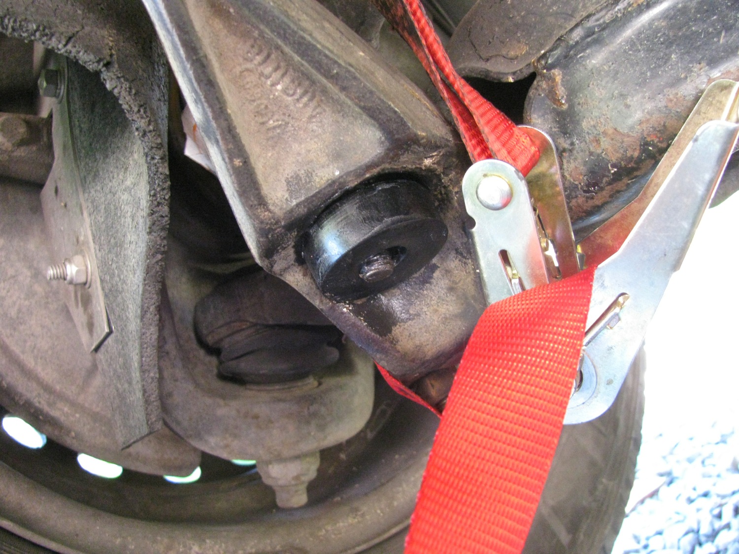
Now the install of the new bushings. Dished washer on the drop link first, convex side facing bushing, then a bushing with sleeve installed in it and the drop link inserted in the control arm. van lowered off the blocks so the drop link is pushed in the control arm. but the new bushing is tight and not much of the other end sticks out. So even with van fully lowered, wheel on the ground, not enough drop link is exposed to get the other bushing installed.

So i rigged up a ratchet strap and pulled the drop link down. Also disconnected the sway bar to body bracket. Even then it was a bear to get the lower bushing installed.
I certainly couldn’t get my dished washer installed so I pulled the bushing in as tight i could with a plain flat washer and the nut. I would do the nut up tight then remove it, put on the dished washer and try the nut…. just wouldn’t catch the threads. My home made stainless washer was too thick.
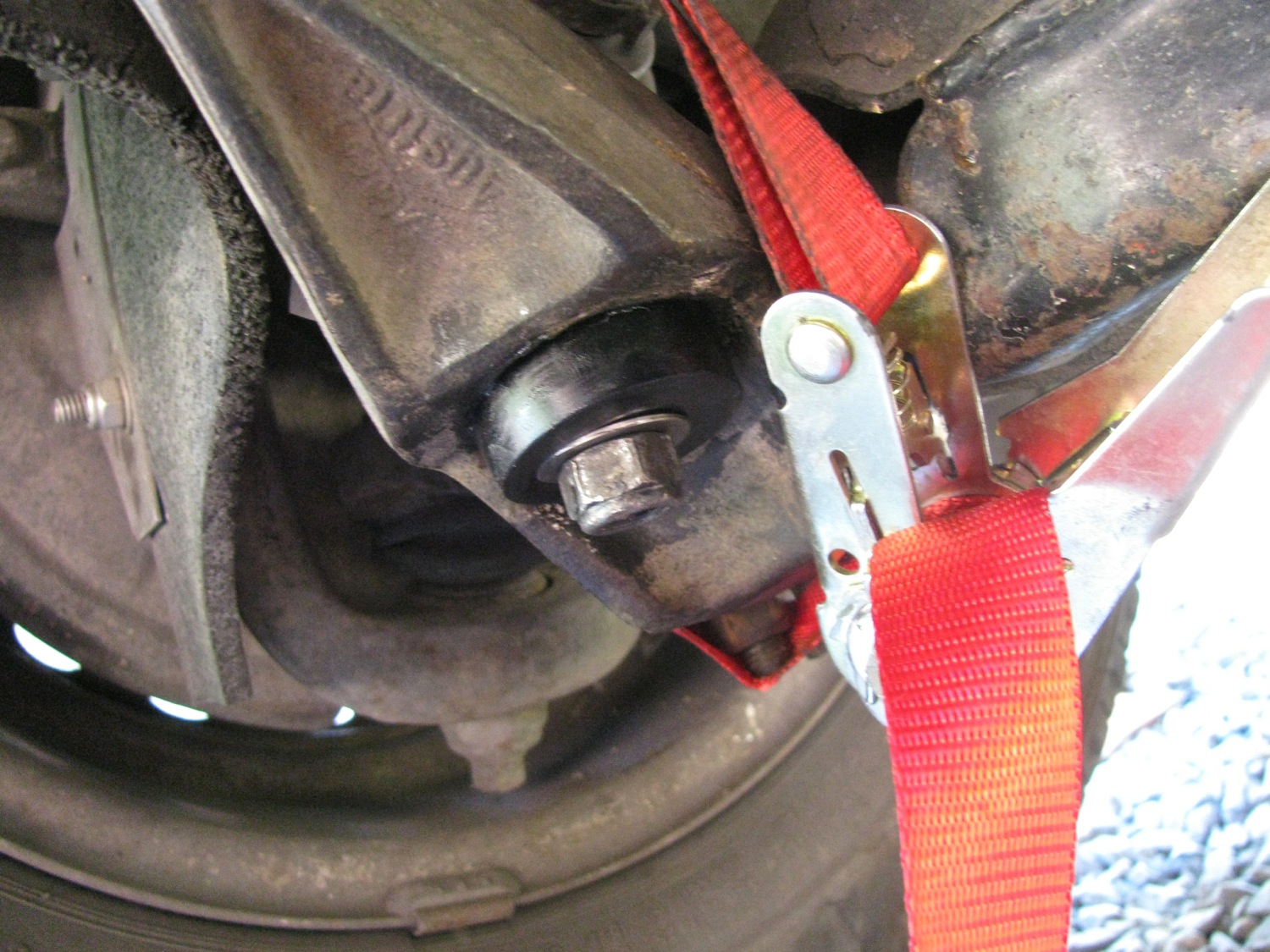
So i turned a recess in the washer and after a bit of a struggle and a lot of cursing, i got the washer and nut on. The other side was a tad easier with the modified bushing. But this part of the job took me a couple of hours.
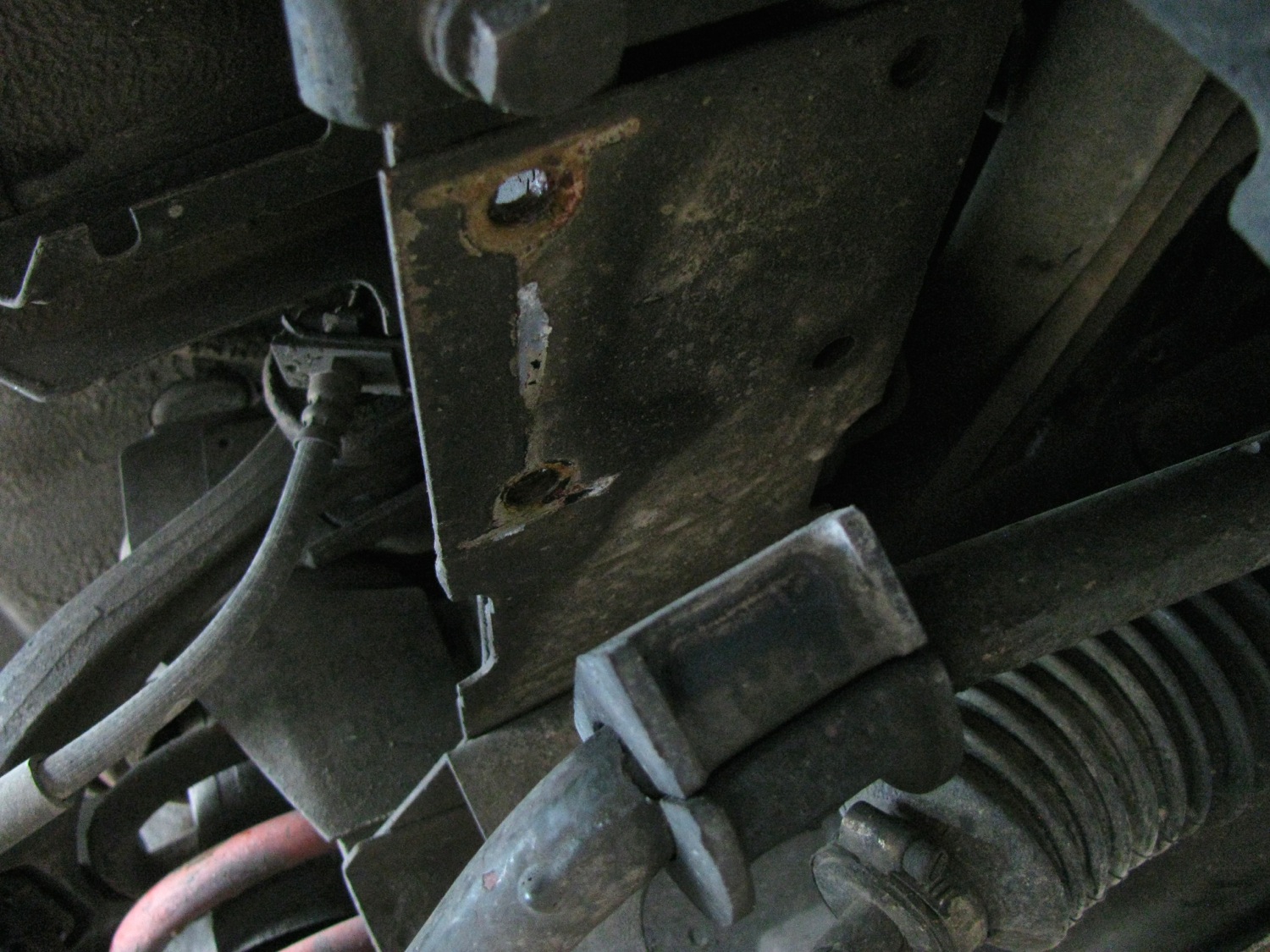
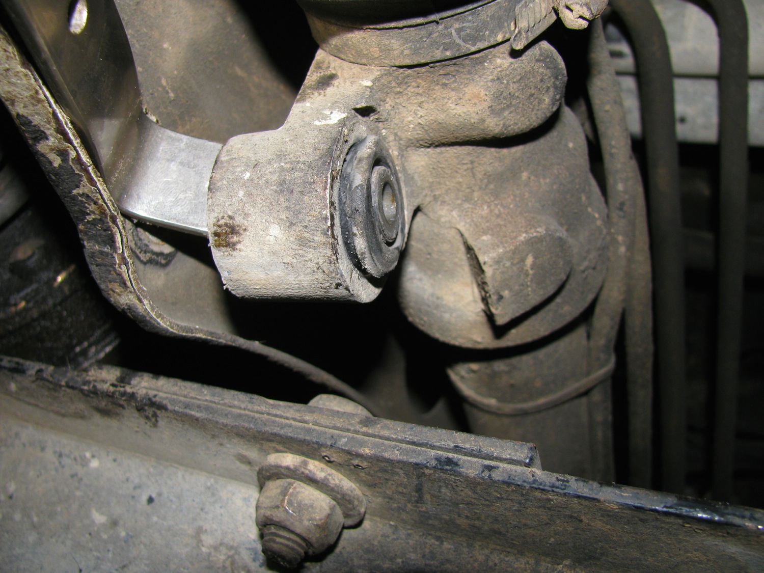
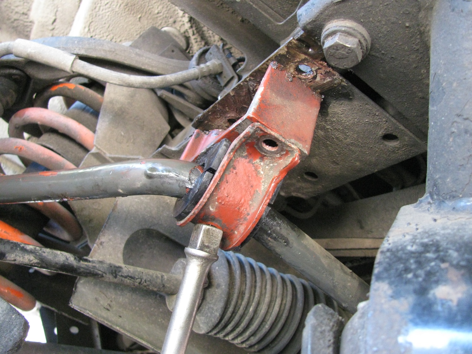
Now on to the steering rack bushings. There are four of them, upper and lower, left and right. Here you can see the lower on the right hand side. The bolt goes throughout the bushing and frame member and there is a stover type nut on the end. I would advise you to soak the nut side with penetrating oil a couple of days before you do this job, there is a fair bit of exposed thread on the bolt and they can be rusty.
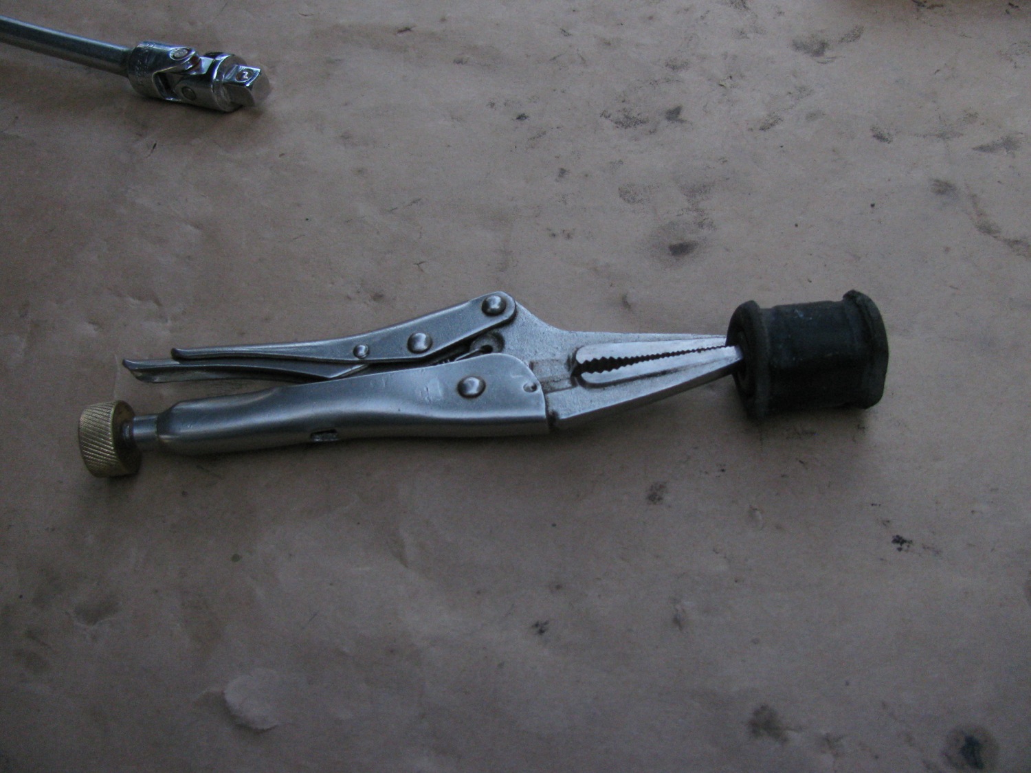
I started by loosening all four bolts, but not all the way. Then had at the lower left side bushing. I removed that bolt, oh careful, there is s slim washer under the nut. The with a slim small pry bar i pushed the bushing out from behind. Remarkably it came out quite easily. On a couple i grabbed the bushing with needle nosed vice grips to ease its passage.

They seem to be in pretty good shape.

The new bushings are two piece with supplied sleeve.

Pretty easy to install. I did one at a time but didn’t tighten up until all installed.

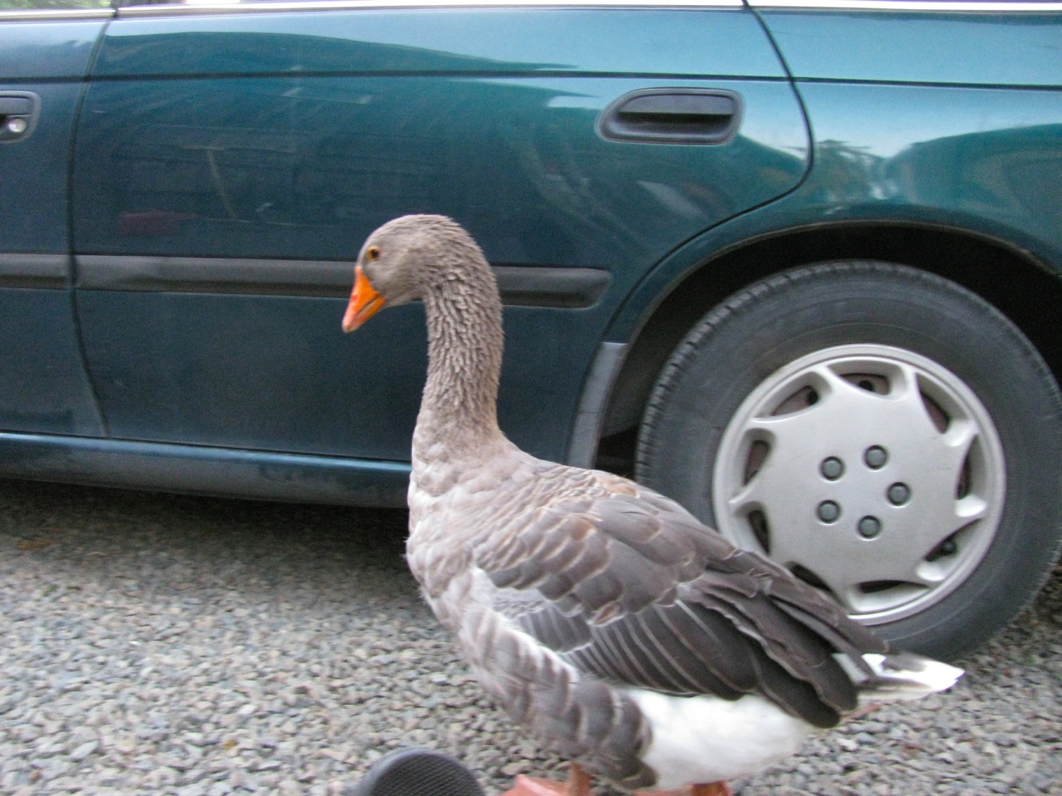
Yeah, supervisor was checking in.
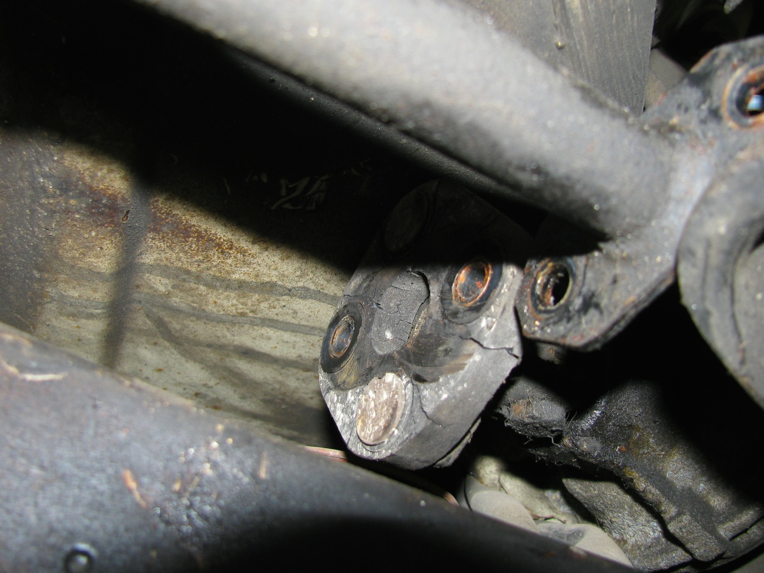
Now on the driver’s side the steering rod (from steering gear box to steering rack) prevents the steering rack from being pried forward enough to both pry out the old bushings and install the new bushings. I disconnected the coupling at the forward end of the rod and loosened the slimed coupling at the u-joint in the rod. It was only later, looking at the pics did I notice the cracks in the rubber coupling, sheesh, another thing to replace.

Wrench access on the driver’s side is a bit restricted, so it take a little longer. But these bushing took less time to install than the drop link bushings.
So the verdict? I could really notice the steering response improvement, especially at highway speeds. I’d recommend the rack bushings even if your existing bushings are in good shape.
