Archive for category syncro
Vanagon rear wheel bearing replacement
Posted by albell in syncro, syncro specific repairs, vanagon on April 16, 2011
I noticed some play in right rear wheel (jacking up van and trying to move wheel, 12 and 6 o’clock positions) and a whiny noise when driving which changed in loudness on turns. I figured it was time to replace the bearings. These bearings seem to last a long time but there is a limit I guess. For another good description of this procedure have a look at the English translation of the German IG16 wiki entry. To start here are a couple of exploded diagrams showing all the parts. 
 It makes a lot of sense to take out the axle at same time so that you can re-lube the CV joints and also press the stub axle into the bearing housing on the bench. But I didn’t do that as I was short on time. If you do want to take out the axle, undo the transmission side CV joint when you still have the wheel on the van, unless you are using air tools, so that you can brace the wheel when undoing the CV bolts. First thing is to undo the 46 mm castle nut on the wheel. It’s on there tight (275 – 350 ft/lbs) so you need to do it with the van on the ground and the wheels chocked. Normally I use a 3/4″ drive socket and a long armed drive with some steel pipe as an extension. But this time I tried out one of those “slug wrenches”, I was given one a few months ago. The idea is that (after removing split pin on nut) you attach slug wrench to nut, use a 1/2″ socket wrench drive to apply some force, and at same time whack the slug wrench with a short sledge hammer. Its a bit awkward, the wrench lies close to the wheel so ou have to aim carefully so as to not hit the rim. But it worked, the nut came loose.
  Once the nut is loose, you then loosen wheel nuts, jack up and support van securely, and remove wheel. Then remove nut and the brake drum should come right off easily. Perhaps you might need to back off brake adjuster if the brake shoes hang up on a lip if your drums are old and worn.
 Next step is to undo brake line from the brake cylinder and cap it with a bleeder nipple rubber cap. Then remove the 13 mm bolt that holds the brake cylinder to the bearing housing. Then remove the 2 bolts (15 mm?) from the brake shoe holder at the bottom. I then removed the clip that holds the parking brake line to the underside of the trailing arm so that I could keep the parking brake line attached to the brake mechanism. The brake assembly and backing plate *should* pull off the bearing housing. However, it is located on the housing by one dowel pin on the brake shoe holder at the bottom. The dowel was stuck in there tight and I had to tap it out with a small brass drift and hammer. Don’t use a steel drift to do this, it will mushroom the dowel.
 See the dowel pin below the bolt holes in above pic? Wet area on trailing arm is due to some rust busting liquid I squirted on exposed threads on the 4 bolts holding the bearing housing on to the trailing arm. With the parking brake line detached from trailing arm it is possible to to pull off brake assembly from stub axle and lay to the side on the ground.
  Now remove the 4 bolts (17 mm?) that holds the bearing housing onto the trailing arm, and then the housing should pull right off the stub axle.
  Pretty ugly in there eh? Caked on dirt and some rust. I took the bearing housing to the bench for disassembly.
 The grease seals were stuck in tight, I had to put the housing in the vice and use a longish pry bar to pop them out.
  Above pic shows outboard grease seal removed and the inner race of the outboard bearing removed (it just falls out). On the inboard side, after the grease seal is removed there is a circlip to take care of.
  After circlip is removed the inner bearing can be removed by driving it out with a brass drift from the outboard side. The spaced sleeve in there between the bearings can be shoved to the side so that you can get the drift onto the bearing race. It took a bit of “drifting” to get the bearing out. If you have a press then you know how to do it better. Once that inboard bearing is out, the spacer is removed and then the outboard bearing outer race can be driven out. In my case that bearing was really stuck in tight. I used an old disk brake caliper piston to drive the bearing out, was a lucky good fit.

 There is a spacer in that gob of grease.
  Cleaned up the housing a bit, especially the bearing seats.
 All the parts arranged.
  Inboard bearing greased and carefully tapped in using that plastic headed dead blow mallet. Picture shows bearing started in housing, not fully seated.
  Bearings were tapped in carefully (a press would be better), the circlip inserted in the inboard side, the spacer installed and the grease applied liberally around the spacer, and the grease seals carefully installed. Again, picture shows bearing started, not fully seated.
  Now at this point, with the housing reassembled, if I had taken the stub axle off the van it would be pressed (or carefully tapped) into the bearings. But what I did was take the housing out to the van, slip it onto the stub axle making sure I didn’t damage the grease seals and that the spacer lined up on the shaft, and I pushed the housing onto the stub as far as I could. I bolted the housing to the trailing arm, then I used the brake drum and the big nut to slowly draw the stub axle into place. This method worked well. Oh, before I put the housing back onto the trailing arm I cleaned out the dirt and loose rust from inside the arm and shot a whack of Fluid Film in there.
  Then its a matter of putting the brake assembly back on, re-attaching the brake line (was a pain, I had to loosen the slave cylinder on the backing plate to get the thread started on the union), then the brake drum, big nut snugged up but not torqued, the wheel, and then get the van off the jack stands. Torque the big nut to spec (see diagram at beginning of post for torque specs), split pin installed, lug nuts torqued, and its done. No play in bearing when the wheel was grabbed, and the whine when driving was gone. I’m guessing that most Vanagon owners will only have to do this job once, or maybe twice, in the van’s life.
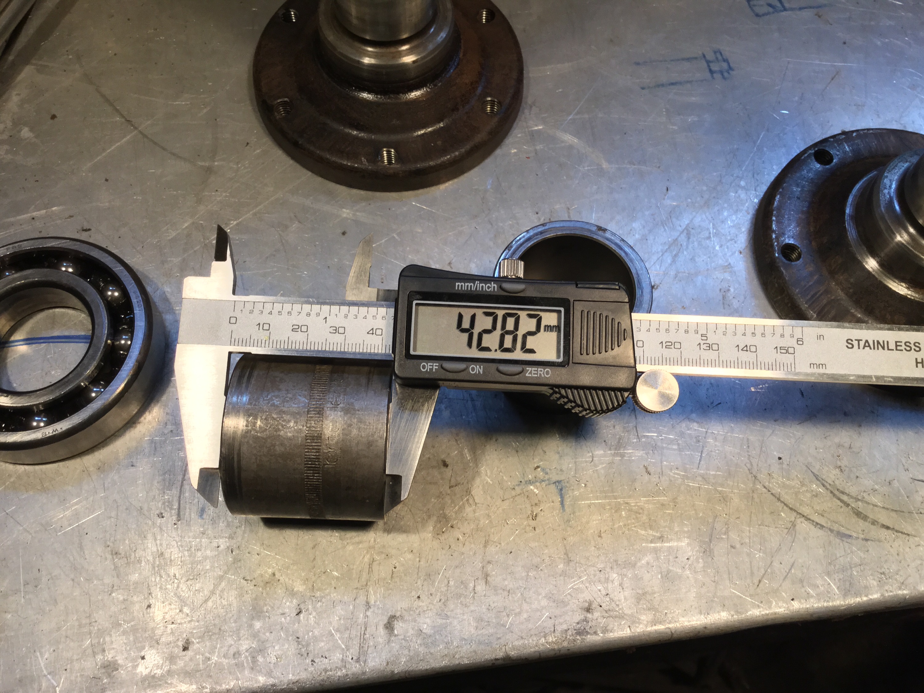
Addendum, April 30 2015, some measurements for Josh 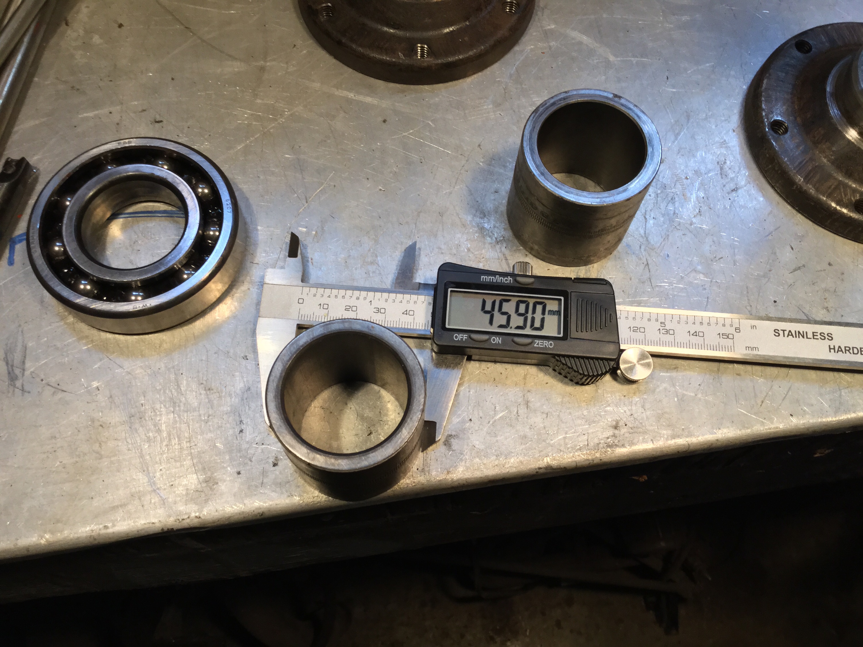


Another logging road trip
This time with visiting Vanagon mailing list pundit David B. We headed to Port Renfrew, then north on that paved road to Lake Cowichan. From there it was logging roads to Nitinat and finally Sarita, a dry sort and booming ground on the south shore of Barkley Sound. Next day we headed west to look at the Pacific at Pachena bay, then north east to Port Alberni and got to see some nice machines behind the scenes at The Alberni District Museum and Historical Society , the Maclean Sawmill museum, and a quick peek at 2 Martin Mars water bombers at Sproat Lake. Then back to Victoria on civilized roads, stopping to look at the big Douglas Firs at Cathedral Grove.
The pics are a mix of mine and David’s.
Quick and dirty Westy table fix
Posted by albell in syncro, vanagon, vanagon mods on March 30, 2011
The old westy table I have in my syncro was loose where the metal base attaches to the tabletop. It used a form of captured nuts in the table top to secure it to the base, and those nuts were loose in the wood, and the holes were chipped and enlarged. I had used some glue to help hold things togther but that was a short lived solution. I think the newer Westy tables have a better system of attachment.
So I set about doing a quick fix. I had some scrap 3/4″ thick PVC sheet:

What was I thinking years ago when I painted that base yellow? I need to repaint it. I cut the PVC to size:

And countersunk some 1/4″ bolts:

Then some PL Premium polyurethane construction adhesive ( the poor man’s Sikaflex) to glue PVC to table:

Now I really do have to get rid of the yellow.
Gordon River trip
Last week my son and I headed out to explore a bit of the Gordon River watershed. The river starts close to Cowichan lake but flows southwest to Port Renfrew and the Pacific. We headed out from home to Port Renfrew then made our way “upstream”. This is the first bridge across the river, near Port Renfrew. Yes, the water was clear and this colour.


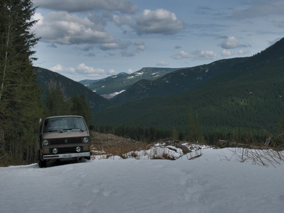
We headed on, exploring various logging spurs to see if we could find a camping spot that had a view, and had some snow. The problem we encountered was that when we found snow on those spurs, it was heavy corn snow, got deepish quickly (20 – 30 cm) and with the steep grades we really couldn’t make much headway.

We ended up at a spot in a recently logged area, about 50 meters below where the snow started.


Well, we had a bit of a view and no shortage of table material.

A word about logging in this valley. I’m guessing most of the watershed, was logged by the middle of the last century. It would have been mostly Douglas Fir and Western Red Cedar, big trees. Now what you see is second growth, Doug Fir, Hemlock, some small cedars. The biggest stumps I saw were about 60 cm diameter. That section in above picture had around 50-60 growth rings. Here are some pic of the recently logged area, showing some old grey stumps from the first cut.


Next day we headed on, again being foiled by steep snow covered spurs, and we decided to try to get to the trail head for Mount Sutton. We found the access road on the north side of the river to be choked with alders. This road starts at the site of the old Gordon River logging camp, which at its peak (1950?) was one of the biggest camps on the island (google map ref). Pretty well nothing remains of the camp now, but if you dig around this site you can find some info and pictures of how it used to be. One strange relic remains, a Mk III Cortina under a fairly large section of cedar log.


You have to be alert for logging trucks, there was about one every 10 minutes.

We headed back west, “downstream” and explored the road that, on the map, leads to the Gordon River Caves. It was another steep and snow covered spur, but we did manage to find a small waterfall and have lunch.


Further west we drove up the north side of the valley, again through logged areas, up steep (measure 29 degrees on one section) spurs, and again foiled by heavy snow. Saw elk tracks though.

We backed down a few meters and found a room with a view.

And some old wolf scat.

It started to rain that night, and the next day. We drove east, “upstream” and came out to civilization near Honeymoon Bay at Cowichan lake. One benefit of traveling on active logging roads is that they are graded often.

It was a fun trip with a few more dents added to the syncro.
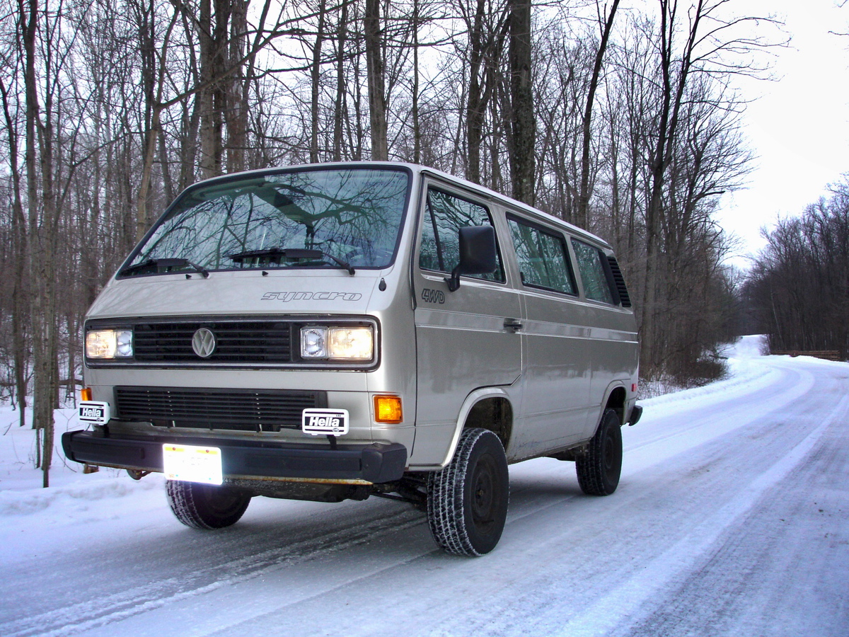
Syncro and Ohio winter
Brett H. sent me this picture of his syncro. Its a good looking van, must ask him about the aux light mounts.
Vanagon syncro propshaft balanced – verdict
Posted by albell in syncro, syncro specific repairs on February 16, 2011
As I mentioned a couple of days ago, I had my prop shaft balanced and I finally have it installed. I drove about 10 km with the front diff. mounts loose to allow it to “settle in”. Today I tightened them down and I can report that the propshaft is pretty smooth. Of course your kind of hyper vigilant in this sort of situation, and I can feel a very very slight vibe at around 60-70 kph, a little like having deep lugged tires. I’m happy with the result.
Vanagon heater hose insulation
Posted by albell in syncro, vanagon, vanagon mods on February 15, 2011
While I was under the van installing the newly balanced propshaft, (prelim. verdict is good, but I haven’t tightened up front diff. mounts yet. Letting things find their happy place), I wrapped the heater lines to the front heater with some pipe insulation. Why did I do both the feed and the return? Well to be honest, I didn’t know which was which. I still haven’t figured out the coolant path through the added hoses that the Webasto heater brings to the party.
The pics make it look like the hoses hang low, but they don’t. White cable ties are all I had. Who cares anyway, its under the fricken van!


Update, 13/05/2011. I’m not happy with the way the insulation is handling the abuse under the van. For one thing, the foam under the cable ties has compressed so that the ties needed tightening. Also the foam is ripped in places, from road debris. I need to find a tougher material to put down there.
Syncro propshaft balanced
Posted by albell in syncro, syncro specific repairs, vanagon on February 14, 2011
I finally had my propshaft professionally balanced by local driveline rebuilder/balancer. The tech took off the factory weights, welded on new ones (washers) and also took out a slight “hump” in the shaft. It was balanced to within 0.001″ run out at each end. I repainted the bare spots and I’ll install it today if the rain stops.

What’s the connection?
One of those tiresome quizzes… what’s the link between this picture of Duncan Hamilton/Tony Rolt driving Jag C type (#18) in the 1953 24 hrs le Mans and a Vanagon Syncro?
")
Doka Magnum Edition
You’ve probably seen these pictures elsewhere, but here they are again.
More info, from T3 wiki, thanks for the heads up Ooznak:
- „Magnum“ (DoKa) hat nichts mit dem Multivan „Magnum“ zu tun und wurde ausschließlich nach Schweden geliefert. Als besondere Merkmale hatte das Modell die Rechteck-Doppelscheinwerfer des Caravelle Carat mit der in Schweden vorgeschriebenen Scheinwerferreinigungsanlage und Stoffsitze mit Sitzheizung.
Google translated as:
“Magnum” (Doka) has nothing to do with the Multivan “Magnum” to do and was only delivered to Sweden. As special features of the model had the square twin headlights of the Caravelle Carat prescribed in Sweden with the headlight washers and heated seats with cloth seats”
Mmm, but the Doka in the slide show has round headlights…
H6 Subie powered Syncro
Seen in passing. Nice van, but I’m surprised at how low the oil pan appears.
Bleeding failure
After refurbishing the pedal assembly I had to bleed the brakes. The rears went ok, but I broke the bleeder nipples from both front calipers. I swear I didn’t wrench hard, was a short wrench and the buggers sheared of easily. Here is pic of the front right, stub of bleeder gnarled a bit as I had a go with vice grips.


I tried spiral type bolt extractor but no luck. I then started to drill, carefully, not full diameter which is 7 mm, and not full depth. I was worried about damaging threads and also the conical base of the hole that forms the seal with the conical point of the bleeder. I then hit it with lots of heat, hoping the shell of the bleeder would separate from the body. No such luck and I got more frustrated and drilled wider and deeper.


I ran a tap down the hole and managed to get some threads restored, but in the end I drilled out too deep and damaged the conical seat at the base of the hole and a new bleeder screw would not seal. Double bugger. Tomorrow I am off to the local wreckers to get a couple of used calipers. What a pain.
Vanagon dash removal, pedal assembly repair, and heater core flush
Posted by albell in syncro, syncro specific repairs, vanagon on February 1, 2011
I’m just about finished with this project. I decided to pull the dash and have a look at both the heater core (I didn’t have as much front heat as I thought I should have) and to fix a squeaky clutch pedal. Removing the dash has been covered elsewhere, a good reference is on Ben’s Place website. Once the dash is out, the heater box can be removed (clamp off coolant lines). One tool that makes this possible is a phillips bit socket on a long extension. Some of the screws holding the heater box to the van can be rusted in tight, so take care. The heater box is then split along the seam, there are spring clips to remove first (and welded plastic tabs if box has not been split before). Then the heater core comes out and I cleaned it inside an out with a hydrofluoric acid based aluminium cleaner. I diluted the cleaner, it was a pretty strong stock solution. Flushing with the cleaner produced a lot of black sediment, I’m hoping that getting rid of that stuff will improve the heater’s performance.
Dash off and heater box out:

Core before cleaning:

The other side:

And a shot of one side after cleaning and installed in box:

Also took the opportunity to squirt some oil on one end of the heater fan. It did feel easier to spin after even this casual oiling:

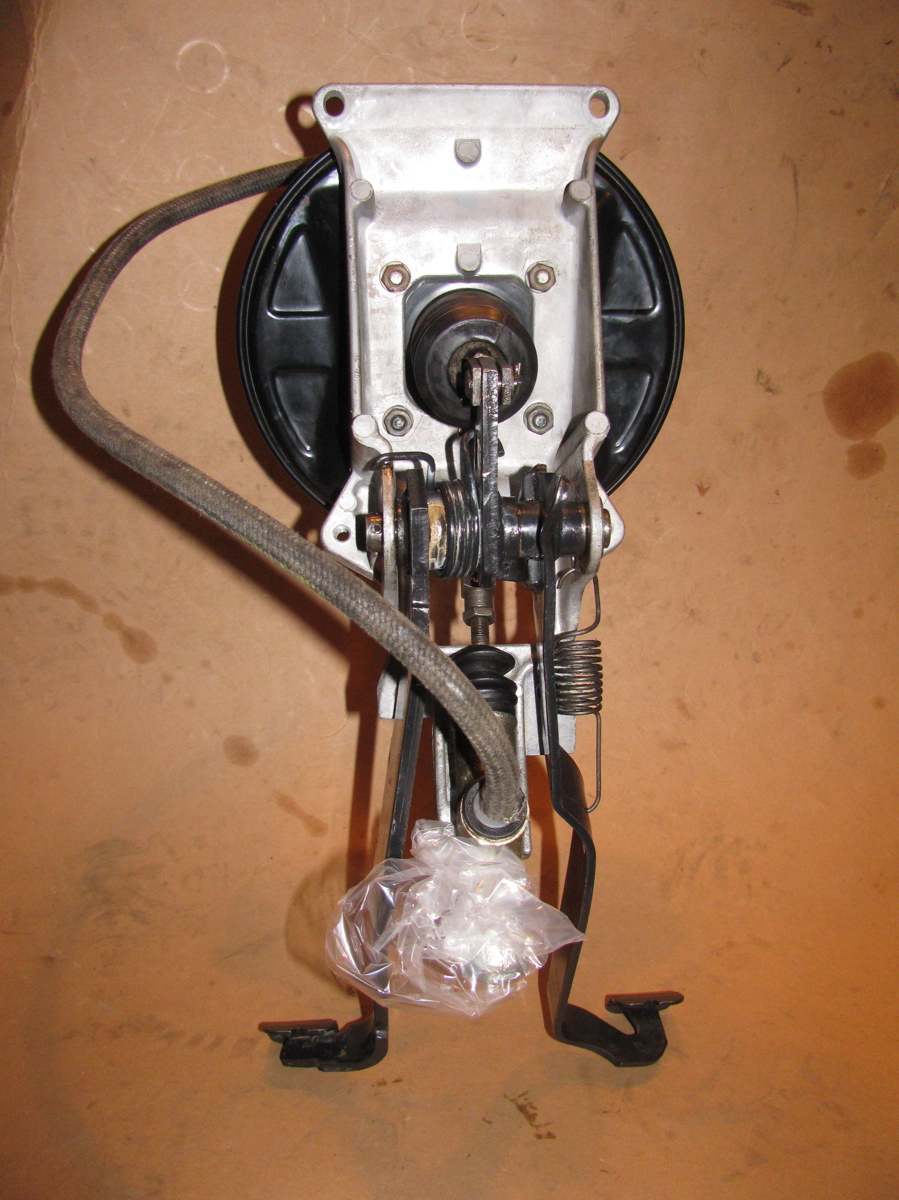
With the dash off its relatively easy to pull the pedal assembly out (after draining brake fluid etc). I have a spare assembly that I rebuilt and talked about in this post, but I decided rather than swap over the units I would rebuild this one. As in the other one, this assembly had a worn hole in clutch pedal and worn clevis pin.

But also, the clutch rod was bent. Wonder how that happened? Maybe previous owner had replaced clutch master cylinder and didn’t insert pin correctly and the first time pedal was depressed it bent the rod before it popped into place?

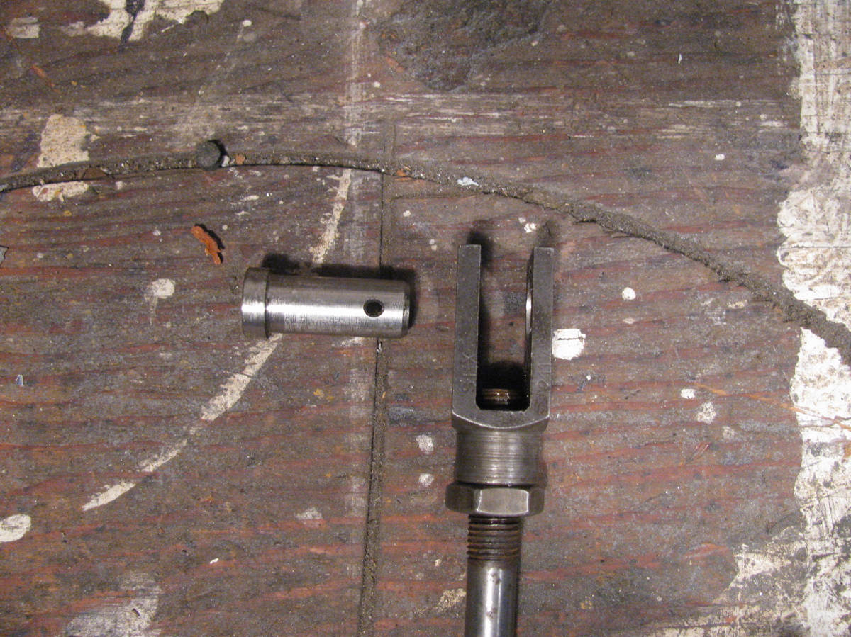
I took the chance and straightened it out, then I enlarged the hole in the clutch pedal and clevis to make it round rather than oval, and turned a new, oversized, (and roughly finished) pin.

Cleaned everything up, greased, and reassembled.

The pedal feels a whole lot better. Now the chore of putting it all back into the van. Nothing special to report here except to note that it is easier to reattach the clutch line to the clutch master cylinder if the mc is disconnected from the pedal bracket. Oh, and a heat gun is needed to soften the plastic vacuum line to the brake booster to get it off, and to put it back on. The dash is back in place and tomorrow I’ll be reconnecting the electrics and flushing the hydraulics.
Vanagon clutch and brake pedal assembly
How can I introduce this? Why not just say that after some time the Vanagon clutch and brake pedal assembly wears a bit at certain points and its a bitch to repair in the van.
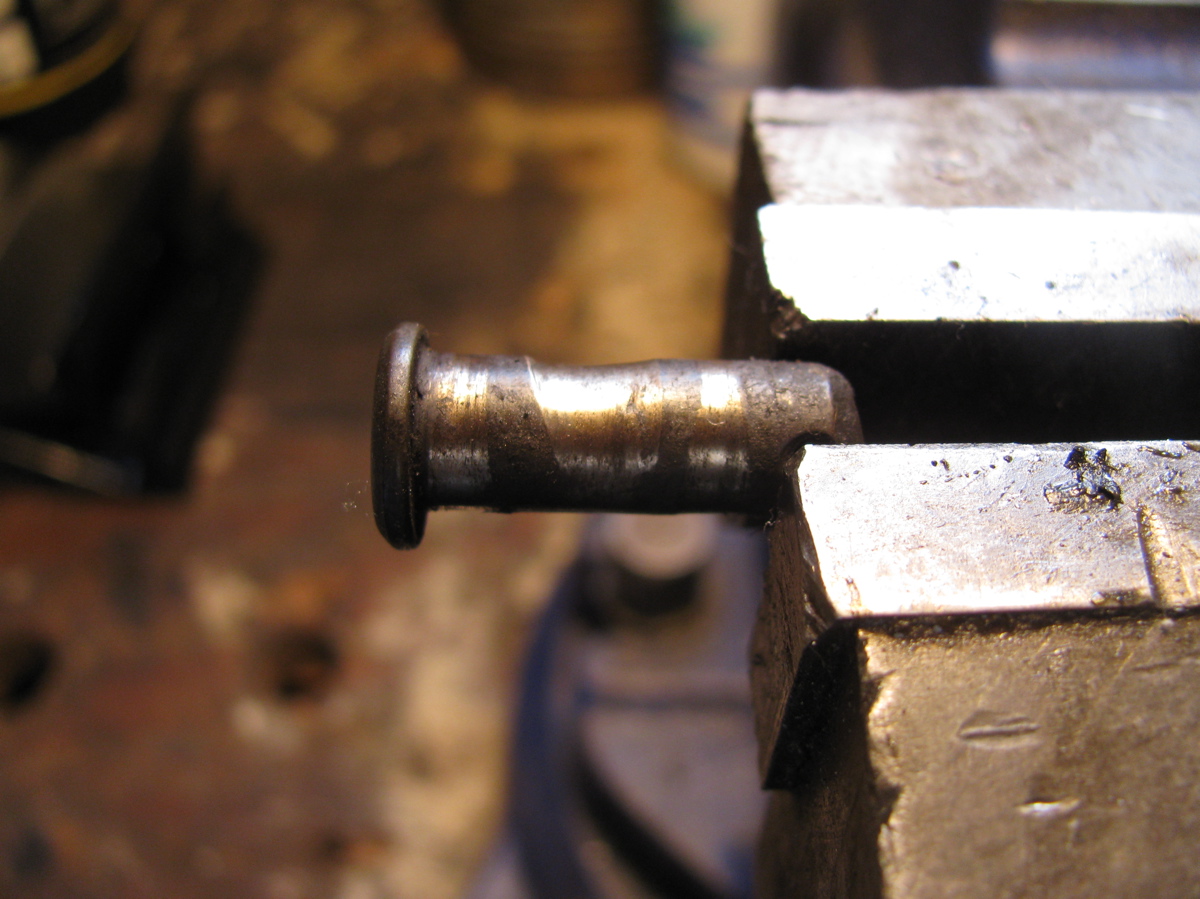
My ’86 syncro has a squeaky clutch pedal and I know why… the metal arm of the pedal has a hole in it where a pin connects it to the clevis of the clutch master cylinder slave rod, and this hole wears into an oval over time. The pin also gets worn. The result is a less than smooth and silent clutch pedal.
I happen to have a complete assembly taken from my dearly loved ’82 westy that I could work on and refurbish.
On the ’82’s clutch pedal the hole was indeed oval and the pin worn (pic of pin in vise is the original worn one). So I drilled out the pedal hole to make it round again (others have filled in hole with weld and redrilled to stock size), also drilled the clevis hole, and I made a new pin out of some stainless stock. Like an idiot, I forgot to take before pics. But the series of after pics show the disassembled assembly and the whole shebang together again. A close up of the clutch clevis and pin included.
One day I’ll swap it into my syncro (it probably means dash removal, but some rumours of being able to get it up and out via binnacle are about). Maybe before I do that, I’ll swap the brake booster for a larger one from an E30 series BMW (see Herman’s blog linked to the right for details).
Oh I should add, if you are like me and can’t be arsed to pull dash to get pedal assembly out for refurb, or at least greased, then you can try scrootching under the dash to get at the bugger. If you lie across the floor, or half in, half out the drivers door, you can reach up with one hand and feel where the clutch actuating rod/clevis connects to the cross pin. You might have to move the clutch pedal with other hand to really get at it. If you put a blob of grease on your finger you can try to massage it around the pin.


Viscous coupling rebuild
Posted by albell in syncro, syncro specific repairs, vanagon on August 16, 2010
In German, on this site http://www.2wd-goes-syncro.de/. Videos showing a VC being taken apart, cleaned, and new fluid added. Well worth a look.
Camperisation Part 2
Posted by albell in syncro, vanagon, vanagon mods on August 11, 2010
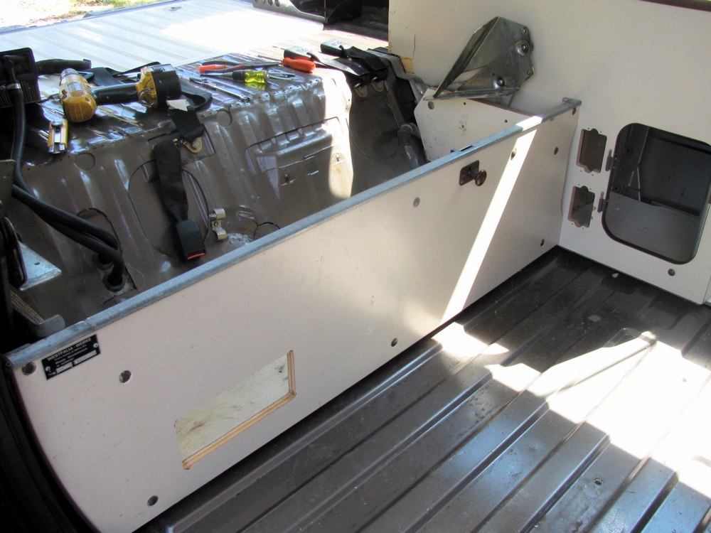
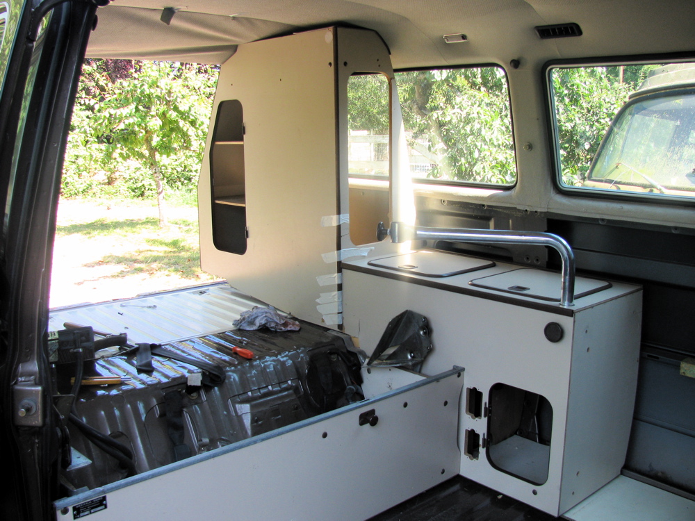
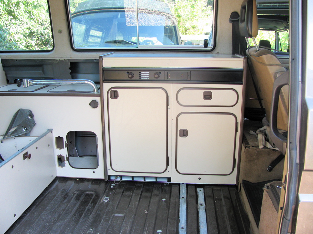
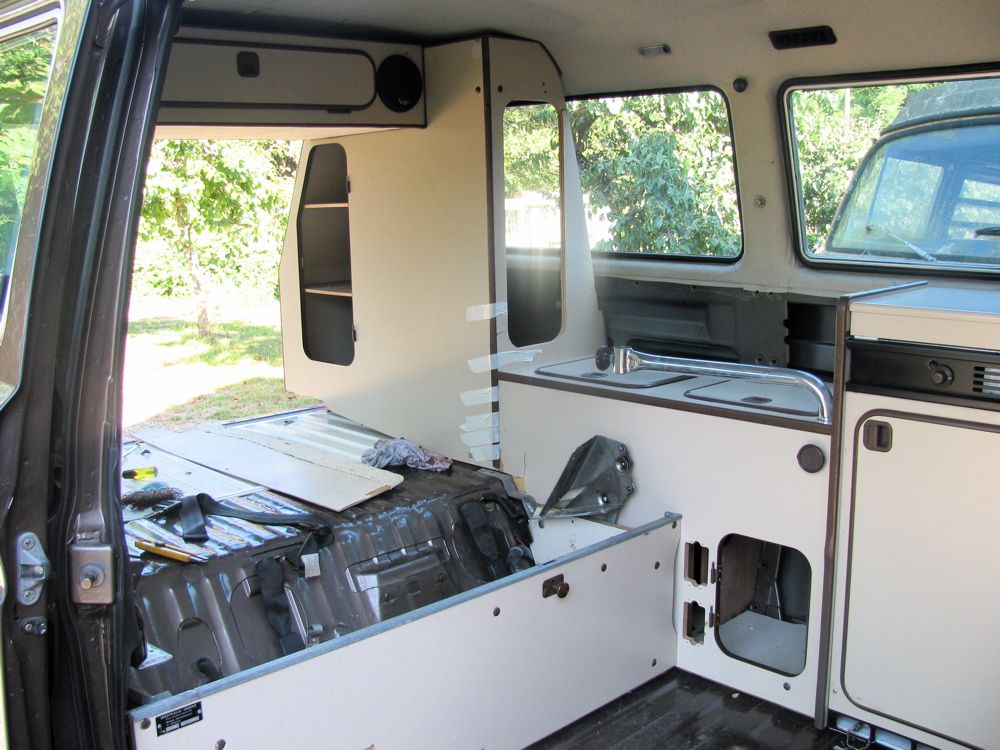
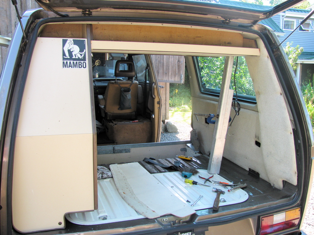
I did some trial fittings and screwed down some cabinets in final positions. Made a spacer for bracket that holds pass. side of rear bench to wall of van. I mentioned in “the start of camperisation” post that the rear bench did not fit as tight to the wall in the syncro as it did in the ’82 Westy. The spacer allows the bracket to be used and bolts the bench tight to the wall.
Wardrobe actually fit in without cutting headliner. Bracket at back on engine deck is fixed in place, and wardrobe is bolted to next cabinet and that cabinet is bolted to rear bench. Its alll pretty secure even though low cabinet not attched to van wall yet and also the rear bench is not bolted down to floor yet.
Overhead cabinet bolted to wardrobe and held up on other end by prop until I figure out a support bracket to hold it to ceiling and to pass. side wall. In the Westy, its bolted to flat ceiling (plywood) which is the upper bunk. You can see how the ceilings differ in that there is a space between overhead cabinet and the ceiling. The Mosaik “kit” has a differently shaped cabinet face to account for ceiling difference. (I can’t seem to find a pic of that modified cabinet right a the moment) I will have to do something to fill gap between cabinet and ceiling.
Apart from little fitment issues, the cabinets went in pretty easily. Next step is making holes for propane lines and watertank and sink drains.
Syncro fuel filter replacement, Part 2
Posted by albell in syncro, syncro specific repairs on August 4, 2010
Got the new filter today, and after working on my wave maker project I set about putting it in.

Installed into bracket.

Tucked behind spring tower, fuel line outlet attached first.

Then filter pulled forward towards front of van and inlet line attached. The the bracket moved into place and attached to tower with the screws. Do the rear screw first, then the front screw. Rear is towards rear of van, front is towards front of van.


Next is reinstalling carbon filter/canister bracket.

And finally the canister itself. I think I installed it higher on the bracket than before, but I don’t think I have crimped any of the lines at the top of the canister.

Overview shot of area.

In hindsight, I guess its not that bad of a job. But I can imagine it being hell with a van that has seen more salty winters. While I was in there, I removed an A/C line and the A/C drier that sat behind the charcoal canister, I’m stripping all the A/C stuff from the van.
Rear seat/bed bracket attachment
Posted by albell in syncro, vanagon, vanagon mods on August 3, 2010
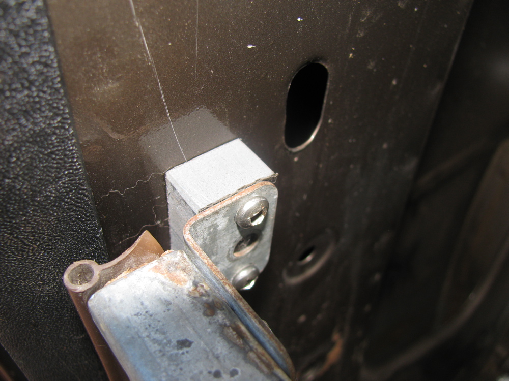
I mentioned before that just drilling a hole through the sheet metal of the rear deck to attach the rear seat/bed brackets is not good enough to get a firm connection. The screws used are self tapping screws which sort of implies, I think, that the factory did not weld on nuts on the underside of the sheet metal. Looking closely into the holes in my ’82 Westy the metal appears thicker than in the same place on my ’86 syncro. Here is view from inside of van of one of the brackets in place (in place but askew).

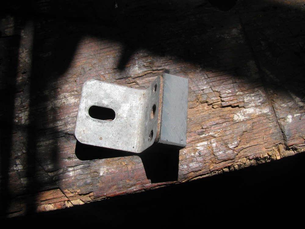
So I set about making some little backing plates to give the screws more thread to love. I used 3/16″ thick stainless bar to make to little plates, 3/4″ wide, 1″ long and a hole in each tapped for 6 X 1.00 mm thread. My plan was to use some Sikaflex to glue the plates to the underside of the deck so that the would stay in place when I screwed the the brackets down. Here is exciting picture of one of the “plates”.

And here is one of the little chaps stuck up in the passenger side rear wheel well where the right hand bracket screw comes through – boy am I slow, it just occurred to me now to check the same place in the Westy to see if there is any similar thing going on. Edit: I just looked at the passenger side rear wheel well on my ’82 Westy where the bracket screw comes through, and lo and behold, looks like a nut is there, surrounded by goop. I assume same thing done for other bracket. So I am not completely mad thinking my little plates will work.
My plate:

Westfalia’s version:

On the driver’s side, the screw comes through above and behind the gas tank of the Syncro.

And here is the plate in place, all smeared with Sikaflex.

I’ll let the Sikaflex cure overnight and then I will remove the screws and I hope the plates will stay in place.
Syncro fuel filter replacement, Part I
Posted by albell in syncro, syncro specific repairs on August 3, 2010
The design team responsible for the fuel supply system in the Vanagon Syncro was led by a descendant of Leopold von Sacher-Masoch. No? Well how do you explain the location of the fuel filter then?
In camperizing the syncro I came upon the problem of screwing down the folding bed/rear bench brackets to the rear deck. I mentioned in a previous post how I drilled and tapped holes, but the rear deck is not thick enough to get more than one complete thread in it, so I went about making some little backing plates to build it up. On the passenger side it is no problem, the area is in the wheel well. But on the drivers side you have to reach up in wheel well, past the carbon filter and behind/above the gas tank. While doing that I decided to change the fuel filter which is located in that region.
Actually the fuel filter is attached to the inboard side of the spring tower. But you wouldn’t know it from this diagram (its #25, oh and the charcoal filter which is part of the emission control system is not shown here).

I did not take an “establishing shot” type pic, but here is a close up of the front side of the spring tower and the charcoal canister (I had removed the gear clamp that holds the canister to its bracket, which in turn is screwed to spring tower).

With the canister moved out the way a bit, you can see the filter, inlet end.
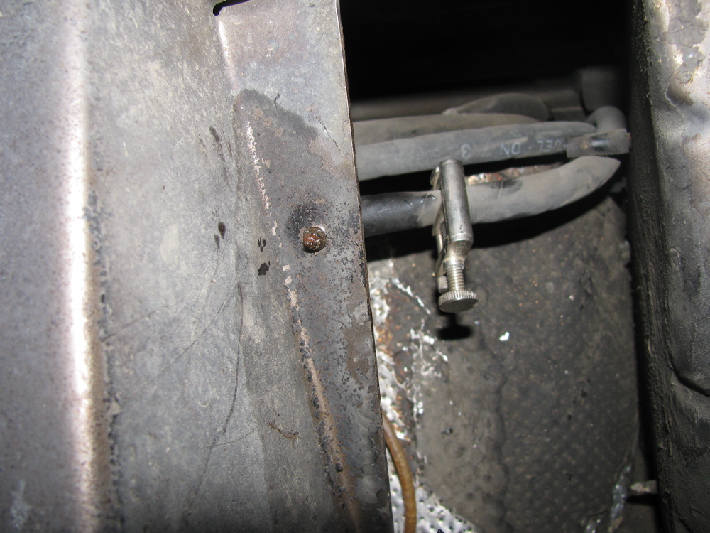
 And if you peer around the rear of the spring tower, you can see the filter outlet end.
 See that screw end sticking out? its one of two 10 mm hex headed screws that holds the filter bracket to the spring tower. I took both out, the “other one” near the front side of the tower is a bit awkward to get at, but I was lucky in that they were not rusted in. By the way, I did squirt all the fasteners with some rust busting stuff before starting. Hello bracket end!
 I clamped the inlet and outlet fuel lines at this point too. I could get at the gear clamp at the outlet side so I removed that hose from the filter.
 Then I struggled with pulling the filter forward, towards front of van, and down to get it out.
 The above picture shows how it doesn’t come out. The charcoal canister, like an annoying relative, kept getting in the way, and the canister’s bracket to the right prevented the filter from coming out… oh wait, why not remove that dammed bracket, doh. Again, two 10 mm hex head screws, and the bracket is off and the filter and its bracket comes out.

 I removed the filter from the bracket, sent the bracket and the charcoal canister bracket into a wash of naval jelly in preparation for painting. Here is the filter still in its bracket and beside it, the charcoal canister bracket.
 Part number for the fuel filter is 450 905 030. Its used an a number of VW vehicles from the 80’s/90’s, should cost around 10 – 15 bucks.
Freed from its bracket, the filter underwent surgery.
 The exposed paper filter elements were incised then retracted.

Yuck. I bet its the original filter.
The brackets are painted and now drying, tomorrow the new filter goes in. See that in Part II
Syncro Westy – rust treatment and Zetec engine
Posted by albell in syncro, syncro specific repairs on June 29, 2010
Whereas I just poke around the fringes of syncro repair, Ed In Vancouver goes deep with rust repair and a Ford Zetec engine swap. His website is here.
prop shaft alignment quick test
Posted by albell in syncro, syncro specific repairs on May 23, 2010
I had time today to do a quick check of the alignment of my prop shaft, or rather where the prop shaft goes, as I have it out right now…
I have to reiterate, this was a quick test, approximate measurements only. I attached my laser alignment jig to, in turn, the transmission output flange, then the front diff. input flange. Each time I measured down from the centre of the opposite flange to where the laser dot was. I also measured the distance between the centres of both flanges.
I did not measure any lateral alignment this go round.
What I found was the front diff was pointing down at a lesser angle then the rear transmission, 2.45 degrees vs 4.45 degrees. Ideally the angles should be equal and less than 4 degrees (but not zero degrees).
Here is a diagram of my results:

If you slept through trig, what you need to know is the TOA part of SOHCAHTOA. TOA means tangent = opposite over adjacent. For example in diagram above, for transmission flange, the tangent of the angle is 100/1285 -> 4.45 degrees. Just do the 100/1285 bit on your calculator then hit the tan-1 button.
Here is a diagram of how U-joints can be oriented:

You can see how my syncro is in the “W” bend form, but the 2 angles are not equal. The angles must be equal, or damn close, to eliminate vibrations. This means I have to adjust the angle that the front diff. sits by shimming the front mount.
Request for viscous coupling

If anyone has an old clapped out viscous coupling they would like to donate, please leave me a message in the comments. I’d like to take one apart, look at the seals, the plates etc.
Syncro running gear layouts
Nice to see it all laid out like this. First we have an overview of viscous coupling installed driveline. This has both rear and front differential locks.

Another view of same.

And here we have the much much rarer version. No viscous coupling, where it was is now a straight shaft. Power to front is now controlled by a de-coupler housed in nose cone of transmission.

And here is cross section of the front differential, showing viscous coupling install.

And a cross section of the rear differential and transmission.
![]()
Syncro front diff. removal
Posted by albell in syncro, syncro specific repairs on April 3, 2010
Look, its cold and windy today, hail at times. I don’t want to freeze in my cold workshop so I am sitting at the computer, ok?
Courtesy of Kafer and Co., Homburg/Einöd is this pdf file showing how to remove your syncro front differential when you want to swap in that new or rebuilt viscous coupling. PDF with pictures, about 800 kb.
A wide open viscous coupling
Graphic shots here from the Wikipedia entry on viscous coupling. I think they were supplied by some English chap who cut open a failed unit. Note the colour of the fluid, I wonder if this colour is due to old age break down, metal particles, or its the stock colour for the polymethylsiloxane and any additive the maker adds. The plates have either notches on the outside (engage with VC housing and flange shaft), or on the inside (engages with pinion shaft). The piercings on the plates are there to reduce heat induced warping. I think its the tiny burrs produced when those plates are pierced that are referred to in the abstract posted previously.


Might as well throw in a sectioned diagram of the VC to perhaps make things more clear.

More on humping
Link bait title, teasing just like this abstract I found. Full text not available but it explains more about how the burrs formed during the piercing of the plates act in the humping state. Also interesting note at end about temperature mediated viscosity changes, something I have been railing against as the cause of torque transfer in the VW vc. I’m sticking with that opinion until proved wrong 🙂
Title:
Numerical analysis of torque augmentation in viscous couplings
Authors:
Pan, Chen
Affiliation:
AA(SYRACUSE UNIVERSITY)
Publication:
Thesis (PhD). SYRACUSE UNIVERSITY, Source DAI-B 59/07, p. 3659, Jan 1999, 153 pages.
Publication Date:
00/1998
Category:
Engineering: Mechanical, Applied Mechanics, Physics: Fluid and Plasma
Origin:
UMI
Abstract Copyright:
(c) 1998: UMI Company
Comment:
Publication Number: 9842398; Advisor: Lewalle, Jacques
Bibliographic Code:
1998PhDT…….126P
Abstract
The humping phenomenon in viscous couplings is investigated by the finite element method. The possible destabilizing factors suggested by the experimental results are divided in two groups: fluid properties and plate geometry. A simple two-dimensional model capable of including these factors was devised. Both Newtonian flow and Non-Newtonian flow in the viscous coupling were solved by our Finite Element Method code. The finite element formulation based on the variational principle is discretized by the mixed interpolation functions. Within each triangular element, velocities were approximated with a quadratic function and the pressure was represented with a linear function. The non-linear system of equations resulting from the discretization process were solved by Gaussian elimination and iteration procedures. As a result, several routes to humping in viscous couplings are documented. The plate permeability associated with the perforations was found to have no significant effect on the humping scenario. The initial loss of symmetry can be provided by random fluctuations of the axial location of the inner plates, or by the presence of burrs. Once the symmetry is broken, the left side burrs at the leading edge of the inner plates can initiate humping with a preferred direction of motion toward the burrs side of the inner plate. It was found that viscous coupling have an ability to recover from the plate torsion. The fluid properties of the silicone oil are also associated with the humping. After examining the power law model, the visco-pseudoplastic model and the temperature-dependent viscosity model for the variable viscosity, it was found that only visco-pseudoplastic model and the temperature-dependent viscosity model can be used to explain the humping. For some transition shear rate (233.3</bar Str<816.5) in the visco- pseudoplastic model, the axial forces will increase the given asymmetry and initiate the humping. For the temperature-dependent viscosity model, the axial force initially stabilized the inner plate, after passing the transition time (0.028 sec), the axial force will destabilize the inner plate and initiate the humping.
Viscous coupling hump condition
Posted by albell in syncro, vanagon tech papers on April 2, 2010

I’m still curious as to how the viscous coupling goes into the hump state. My earlier posts with accompanying documents mention the hump state wherein 100% of torque is transferred from input to output shafts. Recall how the silicon fluid (some form of siloxane) thickens under shear stress and so begins to transfer torque. This shearing increases temperature and consequently pressure inside the coupling housing. VW’s own publicity literature states that the temperature rise is what causes the increase in fluid viscosity, but this research paper disproves that.
The problem I had was wondering what pushes the plates closer together to create the hump state. Just saying pressure increase does not cut it, for the coupling is in a sealed housing and pressure increase should be the same on both sides of the plates.
One thought I had was that there were localised asymmetric pressure increases, but I still had a problem with that as I thought pressure increases would be equalised quickly in a fluid.
Well I was half wrong, the following excerpt from a research paper by Mohan (2002) shows localised pressure increases forcing the plates together. Its a little like tilting your hand out the car window, or is it? Examine diagram closely and make up your own mind 🙂
Oh, STA, self induced torque amplification, is another term for the hump state.

So, as I see it, the progression goes like this:
-rotational difference between input and output shafts (ie front vs rear wheel speed difference, above the 5% or so allowed slippage) causes shear and increasing viscosity in the siloxane fluid.
– at some point, localised pressure differences between plates force the plates together, in effect coupling the input and output plates. Remember the plates are very close together, and one set is on a splined shaft and is free to move axially).
– then the standard story applies, when the plates are coupled there is no relative speed difference between the plates, the shear is gone, and the viscosity drops again, the plates separate and if the input and output speeds remain sufficiently different then the process repeats.
But one thing still puzzles me, in this paper (yes, same one referred to above)
vc-paper
the author notes the pressure increase inside the coupling during slippage, and wonders if some sort of pressure control on coupling could affect the hump state behaviour. I still haven’t resolved how overall internal pressure affects localised inter-plate pressure differences.
And to cap it all off, GKN Drivelines (heir to the Ferguson developers of the viscous coupling) published this bit of info:
See how the diagrams resemble Mohan’s diagrams above, But then they go on to say:
“The “Hump” mode is activated when the coupling achieves 100% filling due to fluid thermal expansion thereby amplifying a hydraulic throttling effect between the plates”
This statement is sort of misleading. Makes you think that the thermal expansion is general (which it is) and not localised (which it is too).
Oh and that reminds me, as you know the coupling is not filled 100% with fluid, there is a small amount of air left in (what is it, 7-12%?). This air ends up distributed, apparently, as small bubbles and acts as a moderating agent in how aggressively the coupling goes into the hump state. For instance, the less air left in, the more aggressive the coupling will be.
Call me an obsessed nerd if you will, but I wish the developers of the viscous coupling (Ferguson et al ?) would call me up and invite me over to explain all 🙂
Nice syncro
I found this series of pics on my computer. I don’t recall where I originally got them from, if anyone recognises them I’d appreciate getting the info for attribution.
Lots of nice touches, one thing especially is the raised instrument cluster which I think would allow a better view of the dials.


Syncro prop. shaft R&R
Posted by albell in syncro, syncro specific repairs on November 20, 2009
This last summer I replaced the original u-joints in the syncro prop. shaft. The previous owner had removed the shaft for the summer, but told me there was some drive line vibrations. There are a lots of tales of woe and intrigue on the net about prop. shaft vibrations, causes and cures, so I decided to have a go at fixing mine. First thing was to replace u-joints. Stock VW joints are expensive, so I used the same replacement joints as Herman did on his syncro project (Precision brand, part #813). The bronze bushings that the yoke assembly and shaft fits into at the guibo end of the shaft seemed ok, the shaft fit in snugly. I just re-greased that, installed the new joints (blanking off the grease nipple fitting holes – I couldn’t get a nipple to fit in the tight spot, you’ll see what I mean if you ever do this job), and then painted the shaft. I re-installed the shaft and still had drive line vibrations at around 50-60 kph. I tried the trick of loosening the front differential mounting bolts and driving the van to let the drive line “find its sweet spot”, but that did not work. I removed the prop. shaft and re-examined it, and noticed some play in one of the joints. I removed that play by installing a thicker circlip (new joints came with two sets of circlips, differing in thickness).
That seemed to have removed the play. I double checked the fit of the yoke shaft into the bronze bushing, was ok.
The next step is to make sure transmission output flange and front differential input shaft are aligned to specifications. They are supposed to be aligned longitudinally, but each flange can be pointing down slightly, 4 degrees or so. I have made a laser alignment tool and I need to get under van and do the deed. One thing that has slowed me down is my suspicion that my viscous coupling is weak, but that’s a story for another blog entry.
Meanwhile have a look at the old u-joints. Notice the pounded marks on one of the bearing surfaces! (apologies for the blurry pic).

