Posts Tagged vanagon
Vanagon – westy luggage rack footman’s loops
Posted by albell in vanagon, vanagon mods on June 14, 2011
When the pop top was on my old ’82 westy I replaced the stock footman’s loops with some stainless eye straps, 2″ Harken, from West Marine, about $2.50 each. Here is Tiny URL to the catalogue page. I find them much better than stock, easier to run rope or attach bungees. The 2″ size fits pretty closely to the stock holes in the luggage rack. When I put them on originally (7 years ago?) I just had to enlarge the holes in the rack with a 5/16″ drill so that 1/4″ stainless bolts would fit. I dug out an old stock loop for a comparison.


Vanagon – Frank G.’s instrument cluster mod
Posted by albell in vanagon, vanagon mods on June 14, 2011
Another article from my old website
Frank writes:
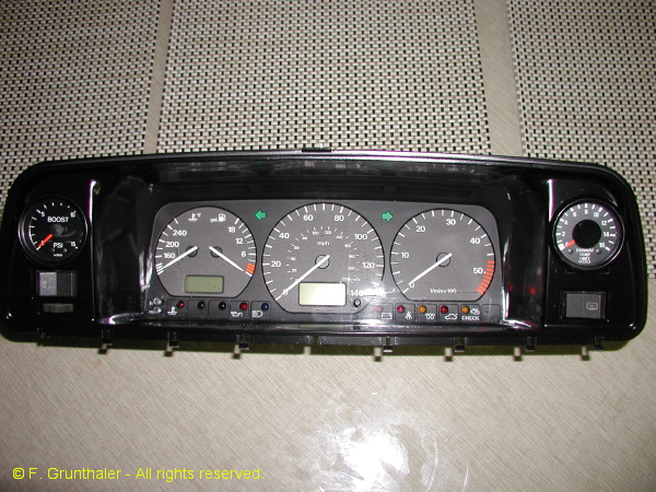
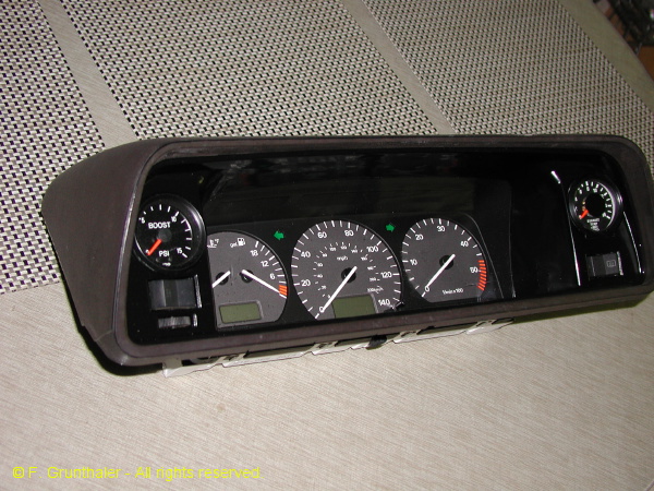
Just finished building a new Vanagon Instrument cluster for my TDi conversion project. I’ve always disliked the Vanagon instrument pod. The center section really offended my sense of completeness. Just looked fake. When I decided to divert the 2.0 Turbo Audi project to the TDI, I decided to do something about it. The result combines the instrument cluster from the 1997 Passat TDI (contributes the gauge faces and front cluster face), a 1995 Passat GLs (contributes the MFA processor calibrated for the 4 cylinder engine), a vanagon cluster, the bezel from a ’97 Passat and a set of VDO gauges.
I’m using the wiper (controls the MFA) and turn signal stalks (controls the cruise control) on the steering column from the 1995 Passat GLS 4-cylinder. Here in the cluster, the temperature and fuel gauges are combined, with separate speedometer and tachometer. The warning light group contains the typical diesel functions. There are two unused light ports. I’m doing transfer logos for them and adding my two color (red/green) LED’s. One of the lights monitors the radiator fan speed (green for low, red for high). The other follows the auxiliary lights with green for Fog on and red for the driving lights. The MFA monitors among the standard features, the engine oil temperature, the average fuel consumption, the instantaneous fuel consumption and the external air temperature. This LCD screen also displays the digital clock.
In the bezel, I add a boost gauge and a pyrometer for EGT measurements. In the lower dash plane I have two gauges, one on either side of the column. To the left, oil pressure and to the right, oil temperature monitored after the oil coolers. In the lower heater face panel, I have a set of five gauges monitoring voltage on the primary circuit, voltage on the auxiliary battery circuit, the pressure in the radiator coolant circuit, an analog clock and an LED compass direction gauge.
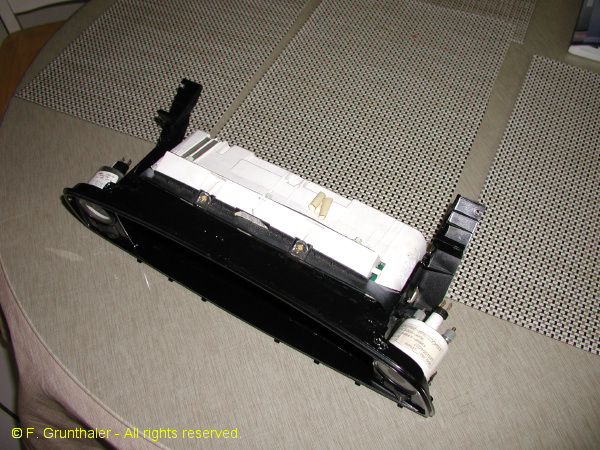
The speedo drive is electronic. I took the rear mount out of an old Jetta speedo cluster I had, cut it up tp keep the frame and the Hall magnet wheel. Then mounted them in a box to take the place of the EGR counter. I use the 3 wire speedo hall sensor from the G/J series. Its a bolt up (or screw up) to the speedo frame. A variable pulse counter frequency adjuster (circuit supplied by my son) will allow variable adjustment for a dead on speedometer regardless of tires and state of wear. Precision wirewound pot for frequency conversion adjustment. Calibrate with simple GPS.
Further notes on fabrication…
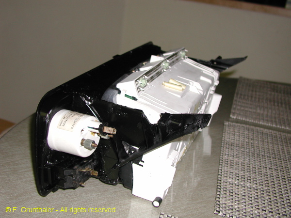
On the master cylinder reservoir interference issue … it was in the way and I wanted to maintain the visual angles, so I took it out! I then used a master cylinder reservoir from a ’90’s Mazda pickup. It comes (from your local P&P yard) with a remote mounting bracket. I rotated it so the long axis is parallel to the windshield long axis. It comes with a built-in level sensor that I wired into the VW harness. I can’t remember if the vanagon originally came with the level sensor built in of if I added it to the vanagon reservoir and modded the harness years ago. For the inlet lines to master cylinder, I believe I used the plastic barb adaptors from a Super Beetle. I use an inline T to tap off the clutch feed. I mounted the reservoir in the same general area as the original Vanagon unit and aligned the inlet so that the plastic drip shield fit again (anal-retentive, I know). Clears the back of the cluster as if it were designed to do so! This solution should work for any cluster one would like to put in!
On the choice of cluster…. Well to start with, I have always thought (going back to March of ’82 when I placed the order for Westfalia for factory delivery) that the instrument cluster was a tacky design. The fake molded sensor lights particularly irritated me! I later years, I added the tach, the oil pressure warning circuits, the VSS speed sensor and redesigned the warning light package to give right and left turn signal lights, added cruise control lights, finally adding multicolor LEDs to the fake center section to monitor radiator fan speed, intercooler fan speeds, fog and driving lights and A/C control parameters. But I never liked the look of the thing.
When I decided to TDi the Vanagon, my orders to the salvage yard were that I wanted it all – engine, hoses, all wires and sensors. To my surprise, they included the speedometer cluster. The three gauge pattern carried the same info as the Vanagon cluster, but much more cleanly. The row of sensor lights along the bottom of the cluster was very tasteful and, the LCD display made it possible to add the MFA (multifunction display) to the package. I noticed immediately that the size of the Passat cluster was just a bit larger than the vanagon center section, so I decided it was time to generate a cluster that was good on the eyes and technically compatible with the Vanagon. The MFA was a key part of the equation, since I could integrate a miles per gallon function together with monitors for oil temperature and all OBD II sensed engine variables (the son is hacking the MFA controller to display all VAG.com accessible info). So, while the A4 cluster is nice and the later sport clusters from the Passat and G/J series are very impressive, they were somehow not in the same design paradigm as the classic Vanagon shape. The approach I used is compatible with any cluster. I chose not to go the digital monitor approach or to rebuild with aftermarket gauges (VDO or other), although the 9 gauge custom cluster seen here on the list recently pushed me from design to implementation.
Key details … Needed – Dremel tool, JB Weld, ’97 Passat instrument bezel, ’95 to ’97 Passat instrument cluster, one or more Vanagon instrument cluster bezels, flexible bumper spray paint, 20+ hours, high quality source of KMZT-FMin garage. To begin, I cut away all the instrument pod from the plastic vanagon bezel to a distance of about 1 inch from the front face. I cut off the bezel support pieces so I could reassemble them to the cluster in the end. I then took the plastic ’97 instrument bezel and used it to shape the remaining vanagon bezel surface. When I has the shape right (easier than it sounds with the Dremel tool) I bonded the passat bezel to the vanagon plastic. This left a series of open areas since the smooth transitions at the top and sides were not a part of the Vanagon shape. These areas were filled with JB Weld then smoothed and shaped by hand with various wet/dry sanding papers. On the back side of the Vanagon cluster, I removed the plastic shell support for everything except for the light switch and the lowest switch position on the right. I then filled and smoothed the front surface in preparation for cutting the two 2 1/16 gauges that I wanted as part of the cluster. I then bonded the cluster support pi eces from the original vanagon bezel to the revised unit. I set the positions in a jig, heat treated the plastic for a slightly different takeoff angel to meet the original mount point without stress. These support pieces were about 0.250 inches further to the right and left than the original. I then fitted the Passat cluster (took off some interfering tabs) and reinforced the remaining structure with JB Weld. The gauge holes and switch areas were then clearanced and a final sanding polish performed before painting with the flexible semi-gloss black. The paint removed fine sanding damage with a high film strength drying surface. Did a test fit and all was well including the latched top pod cover.
On the instrument cluster mods … I added the boost (0-30 psi) and EGT gauges in an excellent 270 degree sweep unit made by Speedhut. The MFA cluster (not part of the original Passat TDi cluster) was pieced together from a ’95 Passat GLs (4 cylinder motor) cluster with turn signal (has cruise control switch) and wiper (has MFA controller) stalks from same. (This idea came from Chris Bell on the TDIClub list). The tach sensing was correct for the TDi engine. The temperature gauge is appropriate for the sensor on the engine. The gas gauge worked for full scale to empty due to VW internal standardization policy! The speedo sensor is electronic. I cut up a GTi speedo cluster to get the Hall effect sensor wheel and mount shell. Added a VW three wire VSS sensor and turned it all into a 2.0 x 2.0 x 1.5 inch adaptor that pops onto the end of the Vanagon speedometer cable. I convert the pulses from this Hall sensor packet to the frequency (pulses per mile) needed by the Passat cluster with either a Dakota Digital pulse frequency converter of a circuit for variable calibration designed by my son. In the custom circuit, we would calibrate the speedometer with a GPS system and thereby lock it on for any tire combination.


Vanagon – stock diesel article
Posted by albell in vanagon, vanagon tech papers on June 14, 2011
Covering the stock, naturally aspirated diesel from Motortechnische Zeitschrift 83 (1981) 3.
It is in German, but some of the figures have English legends.
DV
Vanagon – stock turbodiesel article
Posted by albell in vanagon, vanagon tech papers on June 14, 2011
I thought I’d start posting some of the stuff I have on my old website. First to come is from Motortechnische Zeitschrift 46 (1985) 3.
It is in German, but some of the figures have English legends.
TD article
Vanagon – hacking switches to add LED lights
Posted by albell in vanagon, vanagon mods on June 9, 2011
A couple of kludges here, adding LED lights to the headlight switch and the rear defogger switch. I did this to bug my friend Simon 🙂
First the headlight switch. There are two kinds of switch, one has a white plastic insert in the hole on the back of the switch and one doesn’t. It’s the former that can be illuminated.
Here is a view of the back of the switch removed from the connector and you can make out the white plastic in the hole. Disregard that purple wire soldered to the spade connector, that was a failed experiment.

For a more professional way of installing a lamp into the switch look at this Samba thread. I didn’t have the little bulb holding clips shown in that thread, so I did it a little differently.
Now switch focus from the switch to the connector with all the wires coming out of it, sitting there in dash.
I used a bare bulb white LED and a resistor. The LED fits nicely into the hole in the switch connector and I opened the slots at the base of the hole with an awl so the legs of the LED would fit through. I then could push the LED into the hole and the legs of the LED poked through the other side. I soldered a wire onto one leg and a resistor onto the other. I forget the resistor value at the moment, but you can read the code in the picture. I soldered the other end of the resistor to the black and yellow wire coming into the switch connector. That wire is connected to the X-relay current path, so it get power when the key is on. The purple wire grounds the LED through the handbrake on warning light connecter, the brown wire on that white connector in the picture.

I chose to power the LED from the X-relay track for the reason that I wanted the headlight switch to illuminate when I turned the key, not when I switched on the lights (which seems rather redundant).
Here is the LED powered before the connector is mated to the switch.

Seems pretty bright. The icon on the switch is noticeably lit up even in daylight. I’ll see if it is too bright tonight.
The next kludge is the rear defogger light. There are two tiny little bulbs inside the switch, one to light up the tiny amber dot on the side of the switch when the defogger is on, and one to light up the switch when the headlights/running lights are on. The latter was burned out in my switch. I pulled the back of the switch off (careful, springs and one ball bearing inside), and I put in a LED instead of an incandescent bulb. During the process I broke a little plastic shield that prevents the switch illumination light from also lighting up the little amber dot. One of the pictures shows the shield off, I glued it back on before reassembly of the switch. The leads of the bulbs in the switch are connected to the brass trace by simply being tucked under them. You can pry the trace up and slip the lead of the new bulbs under, then press the trace down again. The resistor can be tucked into a recess in the plastic. I have the negative leg of the LED tucked under the brass at the bottom, which is the “31” spade on the switch, and the positive leg curves up (covered in blue heat shrink) to tuck under the brass at the top, which is the “56b” spade (powered by the headlight dimmer switch). The switch goes back together pretty easily.


Vanagon – westy skylight lifting mech. cover repaint and new knob
Posted by albell in vanagon, vanagon mods on June 8, 2011
That old Delta Six Industries plastic doesn’t age well. I repainted the cover with Krylon Fusion satin black and at same time made a new knob from an old inline skate wheel and a bit of brass.

Vanagon – heckklappen-aufsteller (rear hatch propped open gizmo)
Posted by albell in vanagon, vanagon mods on June 8, 2011
I had a go at making one of those gizmos that allows you to have the rear hatch open a crack, but still locked. I used the plans on this page, specifically this pdf. As shown on that same page, you can make an easier version from a turnbuckle. My attempt is pretty crude, but it works. The D shaped hole goes over the post on the van body, and round hole engages the latch on the hatch.


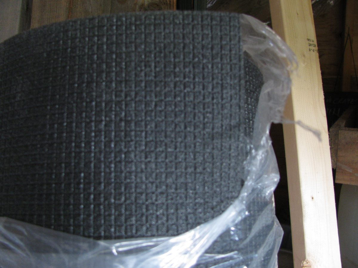
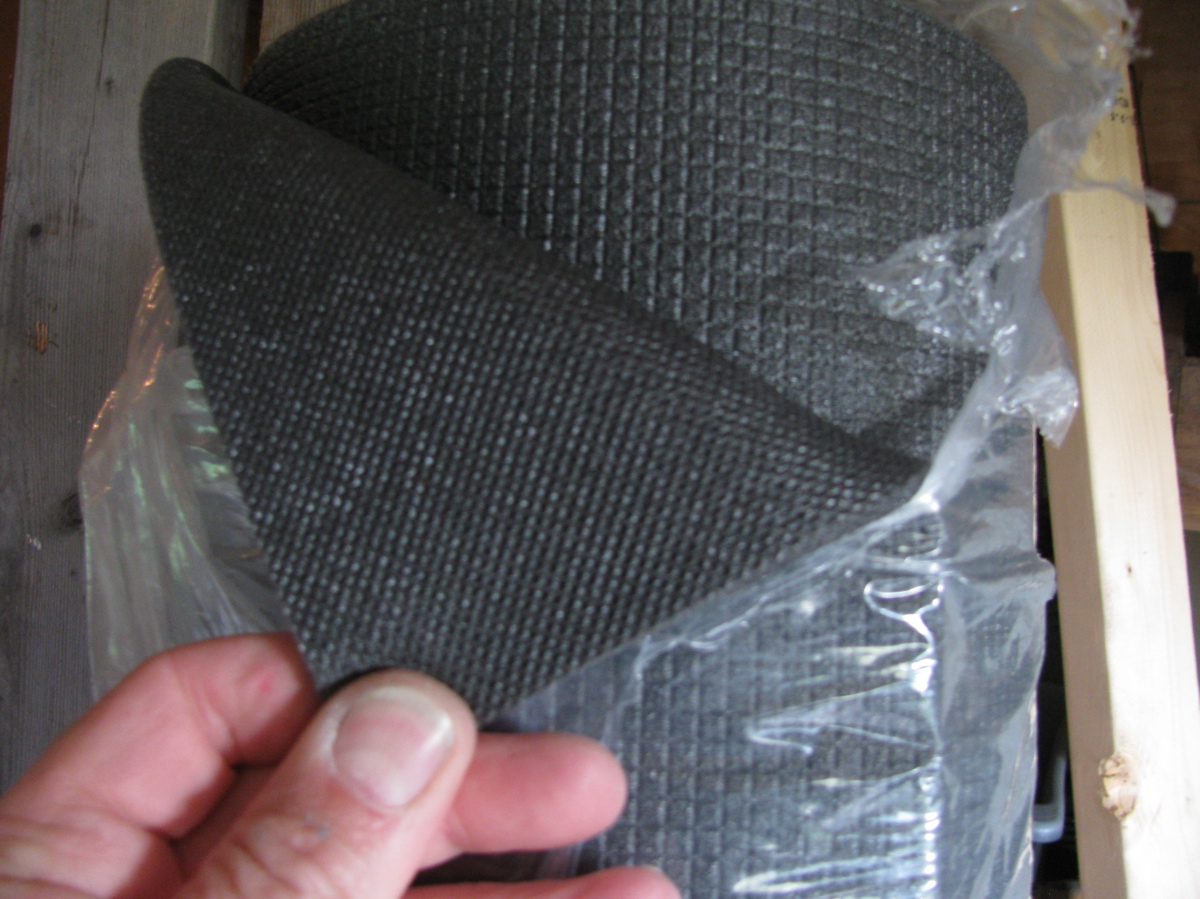
Vanagon pop top insulation idea
Posted by albell in vanagon, vanagon mods on June 6, 2011
I’m planning on gluing in this stuff on the ceiling of the pop top. It is about 3/8″ thick polyethylene closed cell foam. I’m still at a loss whether I should cover it after install, and with what. One guy on the samba insulated with refletrix then covered with fleece. No pictures of that and I can’t imagine how that would look.

Vanagon pop top work – final coat of paint
Posted by albell in vanagon, vanagon mods on June 6, 2011
Scuffed up the first coat and put on the second, both the luggage rack and main top. The dust and bugs were out today, and painting white on white in the sun was difficult, almost got snow blindness.


And a close up of the surface

I’ll let the paint harden for a few days before I do anything else with the top (seals, decals, hardware).
Vanagon pop top work – first coat on top
Posted by albell in vanagon, vanagon mods on June 5, 2011
Sanded the epoxy filled holes and scrapes and put on a first coat. Used a small foam roller and a brush to get into the curves. The paint went on pretty nicely but it a second coat is needed.


Vanagon pop top work
Posted by albell in vanagon, vanagon mods on June 4, 2011
Finally the weather around here has warmed up and looks stable enough to pull the pop top out of the garage and get around to painting it. I power washed it last fall, and did a bit of scuff sanding. I have this notion to insulate the ceiling with some 3/8″ closed cell polyethylene foam so I set about taking the fuzz off the ceiling. I used an orbital sander, which worked well. Then I thought I’d try some paint stripper (had a little bit hanging around), and that worked really well. I’m not concerned about getting all of the tan paint off the ceiling, just the fuzz and around the edges.


Then I used some thickened epoxy to fill some holes I had in the top. While the epoxy was curing I put a coat of paint on the luggage rack.


It’s not a great job and it does need a second coat, but it sure looks much better than it did on the old ’82 westy. Tomorrow I’ll get another coat on it and do the pop top.
Vanagon syncro aux. back up light installed
Posted by albell in syncro, vanagon, vanagon mods on June 1, 2011
I gave up on making an adaptor for the chrome light housing and decided instead to make one for a rubber housing, here it is.


Made of black polyethylene, kinda clunky looking. Jony Ive does not live here. It does seem to work though.


I led the power and ground wires through one of the holes in the rear valence, up over and well away from the muffler, and through a grommeted hole in the heat shield. I do wish there was a better route. I used one of those black plastic electrical box to house the relay.

I used wire I had lying around, not conforming very well to any colour code. I did use a little bus, power is on the right, and ground on the left. I mounted the box onto the plastic “bulkhead” that the air intake snorkel connects to on the right hand side of the engine compartment. I tapped into the black/blue power wire feeding the right hand side back up light to provide the signal power for the relay.

I also put in an old back up beeper I had on my ’82 westy. I was a good thing to have when my son was young and I got used to it, so now it’s on the syncro, just lying in front of right hand side tail lights.

I took power from the alternator stud – NOTE – I have not installed in inline fuse on this feed line yet, one DOES need to be installed. I led a ground to one of the alternator housing screws.

Gack, I need to buy black cable ties. Tested, and works (beeper too).

Vanagon syncro aux. back up light bracket
Posted by albell in syncro, vanagon, vanagon mods on May 31, 2011
I want to put an auxiliary back up light on my ’86 syncro but never have found an attachment method I liked. That is until Brett H. told me about how he did it, so all credit for this bracket idea goes to him. I used scrap stainless stock I had in the workshop (hence the double holes shown) and I have an old bumper that I could do trial fittings on. Pretty simple bracket, easy bends.

It bolts to the bumper using one of the holes that the plastic clips on the rubber “rub strip” attaches to.

The lamp housing is one of a set I found at the Salvation Army some years ago. I had one on the front of my old ’82 westy, fitted with a 250 W aircraft lamp. The test fitting on the old bumper looked ok.

It is possible to attach the bracket while the bumper is on the van.

I enlarged the hole that the plastic clip was set into so that the rub strip would fit over the bolt.

The rub strip fits back on quite well, I was lucky with the hole enlarging, it seems to grab the bolt head.

Attaching the lamp to the bracket showed that I need to tweak things a bit, light is pointing slightly down. I’ll make an adapter tomorrow and show the electrical part of the install. Oh, in the pic above, the bracket is to the right of the license plate (seen on the left).
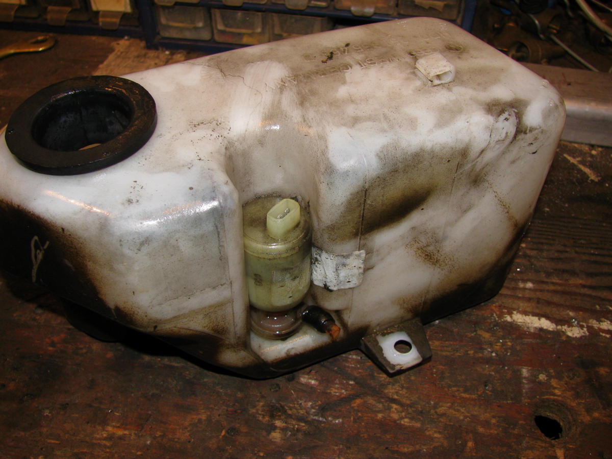
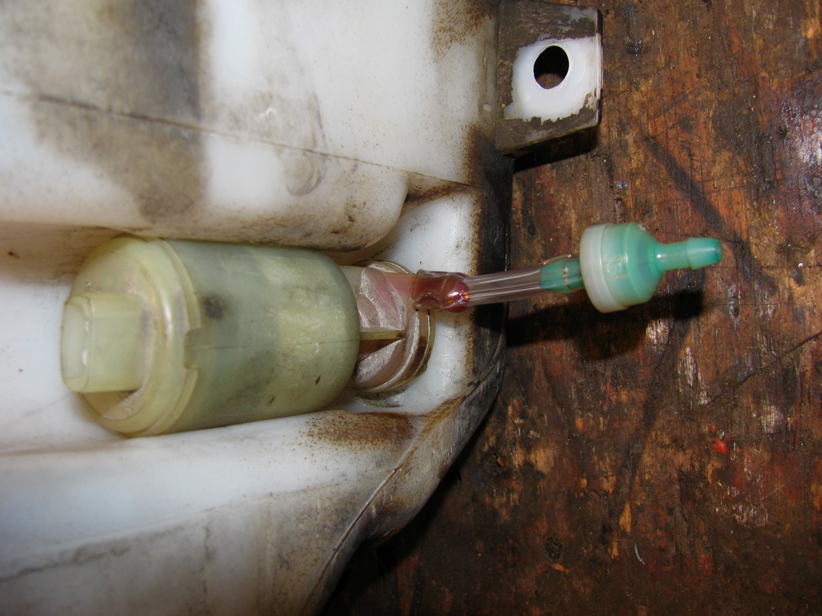
Vanagon – check valve on windscreen washer line
Posted by albell in vanagon, vanagon mods on May 22, 2011
Boy oh boy, this is heady stuff.
Yeah, my son thinks I am a doofus too.
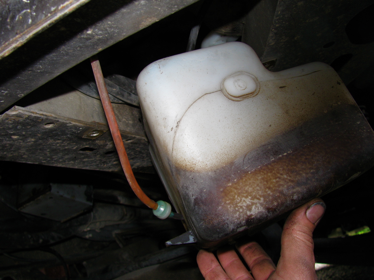
Ok, I didn’t get enough of squirming on my back today when I was working on the shift linkage, I had to drop the windscreen washer reservoir and add a little check valve (found at wreckers on a Vanagon years ago).
Car audio ground loop whine
Posted by albell in vanagon, vanagon mods on April 17, 2011
For the last few months I have been trying to fix a whine coming through the car audio system when the engine is running. It came on all of a sudden, and only on the front speakers which are powered by separate amp and go through crossovers. The noise is present no matter what input chosen: tuner, CD, aux, USB.
What I have tried :
-redid all grounds, signal, and power leads to front speakers, crossovers, and amp
-ran new power and ground wires to head unit
-swapped in another amp
– tried alternate pair of rca jacked leads from head unit to amp, straight run, not crossing power lines
– new antenna and lead to head unit (old one was really bad at head unit)
– if I grounded amp directly to battery post instead of body, noise was louder. BTW, the amp ground wires are a short run twisted trio.
-pulled alternator brush pack and cleaned connections
-pulled the noise reducing capacitors on alternator and cleaned connections
-removed the diagnostic plug (TDC sensor lead and plug) from alternator
-pulled distributor cap and cleaned, above and below black plastic shield
-cleaned up edge of rotor
-cleaned all the grounding points (pivot bolt area etc) on alt. body
I did notice that the whine would disappear if the radio antenna was not connected. I talked to a few people and most told me to install a ground loop isolator on the low level lines from head unit to amp. Yesterday I talked to an ex-car audio installer and he advised to try grounding the RCA jack shields. That advice and the information here, convinced me to try it, and miracle of miracles, IT WORKED! Not a hint of noise or whine. To say I’m chuffed would be an understatement.
The head unit is a Pioneer DEH-P5000UB.

Vanagon rear wheel bearing replacement
Posted by albell in syncro, syncro specific repairs, vanagon on April 16, 2011
I noticed some play in right rear wheel (jacking up van and trying to move wheel, 12 and 6 o’clock positions) and a whiny noise when driving which changed in loudness on turns. I figured it was time to replace the bearings. These bearings seem to last a long time but there is a limit I guess. For another good description of this procedure have a look at the English translation of the German IG16 wiki entry. To start here are a couple of exploded diagrams showing all the parts. 
 It makes a lot of sense to take out the axle at same time so that you can re-lube the CV joints and also press the stub axle into the bearing housing on the bench. But I didn’t do that as I was short on time. If you do want to take out the axle, undo the transmission side CV joint when you still have the wheel on the van, unless you are using air tools, so that you can brace the wheel when undoing the CV bolts. First thing is to undo the 46 mm castle nut on the wheel. It’s on there tight (275 – 350 ft/lbs) so you need to do it with the van on the ground and the wheels chocked. Normally I use a 3/4″ drive socket and a long armed drive with some steel pipe as an extension. But this time I tried out one of those “slug wrenches”, I was given one a few months ago. The idea is that (after removing split pin on nut) you attach slug wrench to nut, use a 1/2″ socket wrench drive to apply some force, and at same time whack the slug wrench with a short sledge hammer. Its a bit awkward, the wrench lies close to the wheel so ou have to aim carefully so as to not hit the rim. But it worked, the nut came loose.
  Once the nut is loose, you then loosen wheel nuts, jack up and support van securely, and remove wheel. Then remove nut and the brake drum should come right off easily. Perhaps you might need to back off brake adjuster if the brake shoes hang up on a lip if your drums are old and worn.
 Next step is to undo brake line from the brake cylinder and cap it with a bleeder nipple rubber cap. Then remove the 13 mm bolt that holds the brake cylinder to the bearing housing. Then remove the 2 bolts (15 mm?) from the brake shoe holder at the bottom. I then removed the clip that holds the parking brake line to the underside of the trailing arm so that I could keep the parking brake line attached to the brake mechanism. The brake assembly and backing plate *should* pull off the bearing housing. However, it is located on the housing by one dowel pin on the brake shoe holder at the bottom. The dowel was stuck in there tight and I had to tap it out with a small brass drift and hammer. Don’t use a steel drift to do this, it will mushroom the dowel.
 See the dowel pin below the bolt holes in above pic? Wet area on trailing arm is due to some rust busting liquid I squirted on exposed threads on the 4 bolts holding the bearing housing on to the trailing arm. With the parking brake line detached from trailing arm it is possible to to pull off brake assembly from stub axle and lay to the side on the ground.
  Now remove the 4 bolts (17 mm?) that holds the bearing housing onto the trailing arm, and then the housing should pull right off the stub axle.
  Pretty ugly in there eh? Caked on dirt and some rust. I took the bearing housing to the bench for disassembly.
 The grease seals were stuck in tight, I had to put the housing in the vice and use a longish pry bar to pop them out.
  Above pic shows outboard grease seal removed and the inner race of the outboard bearing removed (it just falls out). On the inboard side, after the grease seal is removed there is a circlip to take care of.
  After circlip is removed the inner bearing can be removed by driving it out with a brass drift from the outboard side. The spaced sleeve in there between the bearings can be shoved to the side so that you can get the drift onto the bearing race. It took a bit of “drifting” to get the bearing out. If you have a press then you know how to do it better. Once that inboard bearing is out, the spacer is removed and then the outboard bearing outer race can be driven out. In my case that bearing was really stuck in tight. I used an old disk brake caliper piston to drive the bearing out, was a lucky good fit.

 There is a spacer in that gob of grease.
  Cleaned up the housing a bit, especially the bearing seats.
 All the parts arranged.
  Inboard bearing greased and carefully tapped in using that plastic headed dead blow mallet. Picture shows bearing started in housing, not fully seated.
  Bearings were tapped in carefully (a press would be better), the circlip inserted in the inboard side, the spacer installed and the grease applied liberally around the spacer, and the grease seals carefully installed. Again, picture shows bearing started, not fully seated.
  Now at this point, with the housing reassembled, if I had taken the stub axle off the van it would be pressed (or carefully tapped) into the bearings. But what I did was take the housing out to the van, slip it onto the stub axle making sure I didn’t damage the grease seals and that the spacer lined up on the shaft, and I pushed the housing onto the stub as far as I could. I bolted the housing to the trailing arm, then I used the brake drum and the big nut to slowly draw the stub axle into place. This method worked well. Oh, before I put the housing back onto the trailing arm I cleaned out the dirt and loose rust from inside the arm and shot a whack of Fluid Film in there.
  Then its a matter of putting the brake assembly back on, re-attaching the brake line (was a pain, I had to loosen the slave cylinder on the backing plate to get the thread started on the union), then the brake drum, big nut snugged up but not torqued, the wheel, and then get the van off the jack stands. Torque the big nut to spec (see diagram at beginning of post for torque specs), split pin installed, lug nuts torqued, and its done. No play in bearing when the wheel was grabbed, and the whine when driving was gone. I’m guessing that most Vanagon owners will only have to do this job once, or maybe twice, in the van’s life.
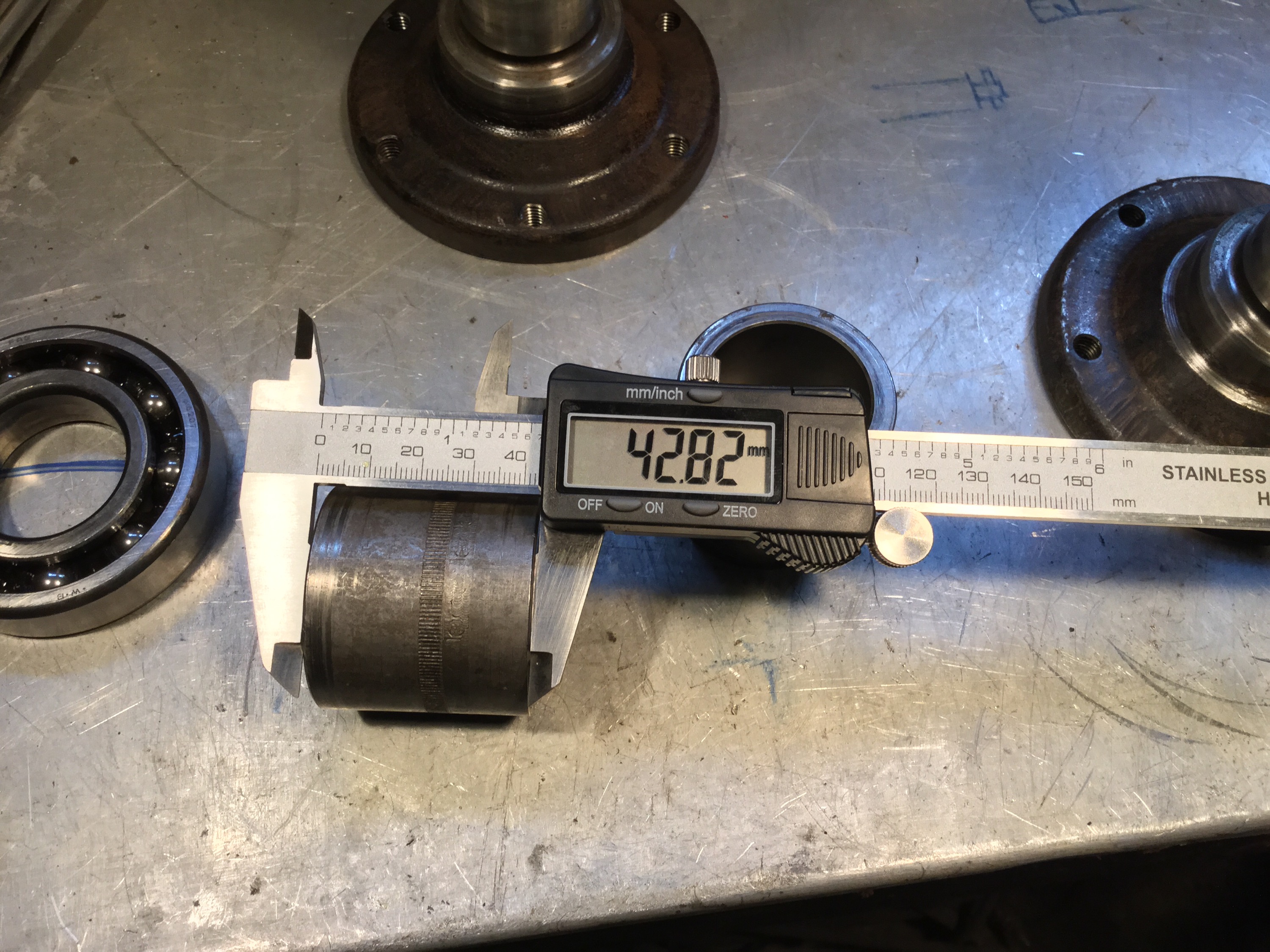
Addendum, April 30 2015, some measurements for Josh 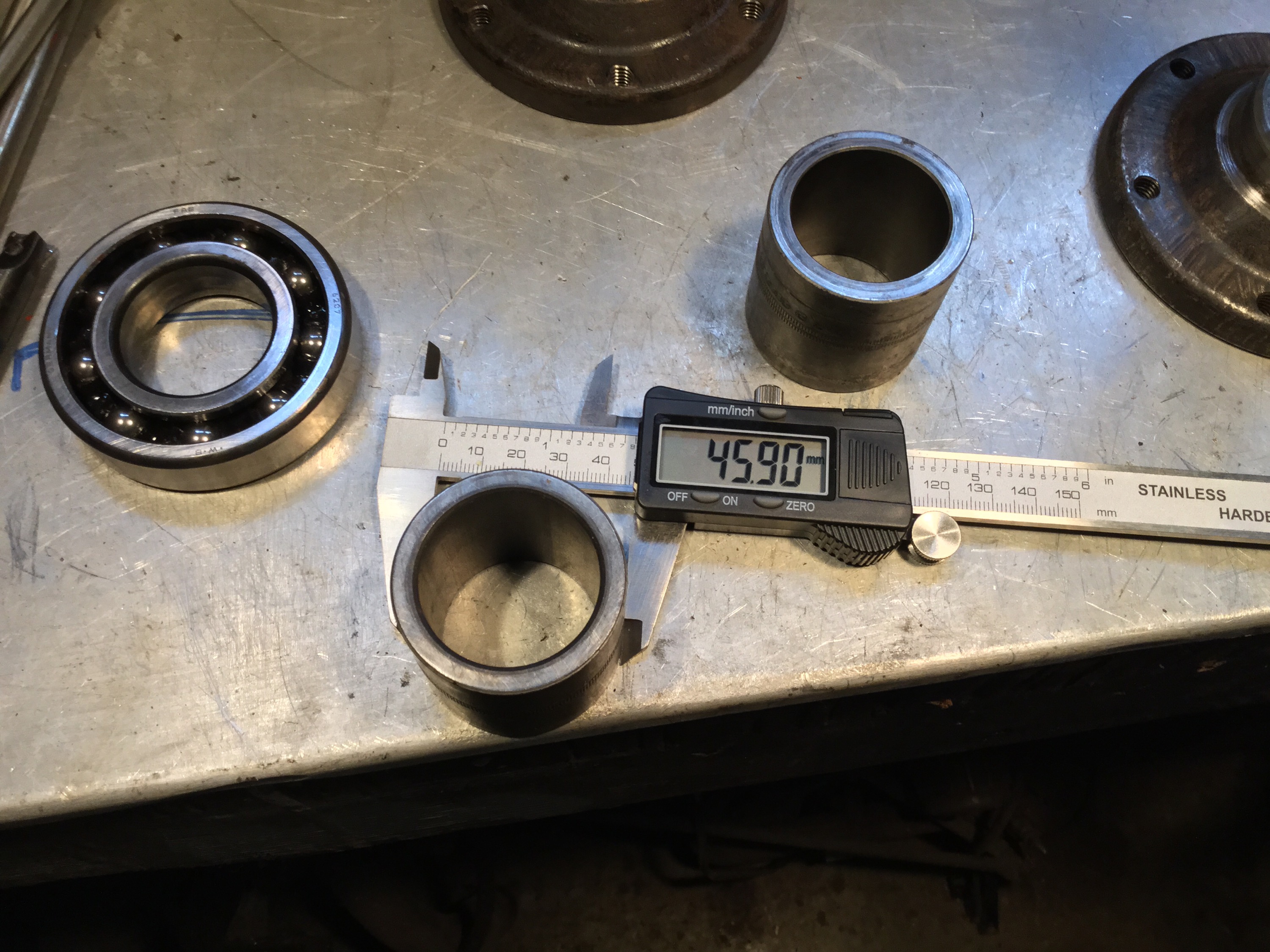


Another logging road trip
This time with visiting Vanagon mailing list pundit David B. We headed to Port Renfrew, then north on that paved road to Lake Cowichan. From there it was logging roads to Nitinat and finally Sarita, a dry sort and booming ground on the south shore of Barkley Sound. Next day we headed west to look at the Pacific at Pachena bay, then north east to Port Alberni and got to see some nice machines behind the scenes at The Alberni District Museum and Historical Society , the Maclean Sawmill museum, and a quick peek at 2 Martin Mars water bombers at Sproat Lake. Then back to Victoria on civilized roads, stopping to look at the big Douglas Firs at Cathedral Grove.
The pics are a mix of mine and David’s.
Quick and dirty Westy table fix
Posted by albell in syncro, vanagon, vanagon mods on March 30, 2011
The old westy table I have in my syncro was loose where the metal base attaches to the tabletop. It used a form of captured nuts in the table top to secure it to the base, and those nuts were loose in the wood, and the holes were chipped and enlarged. I had used some glue to help hold things togther but that was a short lived solution. I think the newer Westy tables have a better system of attachment.
So I set about doing a quick fix. I had some scrap 3/4″ thick PVC sheet:

What was I thinking years ago when I painted that base yellow? I need to repaint it. I cut the PVC to size:

And countersunk some 1/4″ bolts:

Then some PL Premium polyurethane construction adhesive ( the poor man’s Sikaflex) to glue PVC to table:

Now I really do have to get rid of the yellow.
Gordon River trip
Last week my son and I headed out to explore a bit of the Gordon River watershed. The river starts close to Cowichan lake but flows southwest to Port Renfrew and the Pacific. We headed out from home to Port Renfrew then made our way “upstream”. This is the first bridge across the river, near Port Renfrew. Yes, the water was clear and this colour.


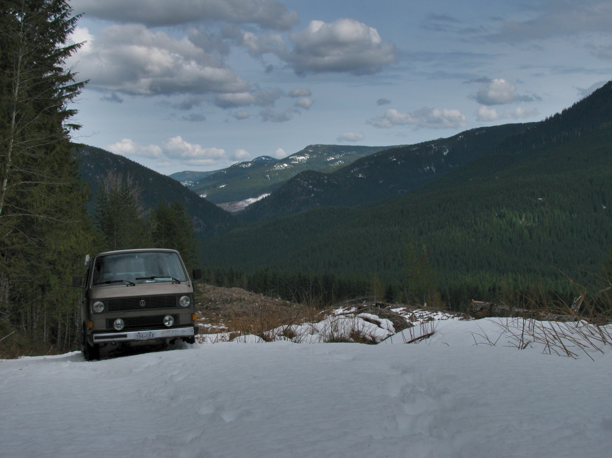
We headed on, exploring various logging spurs to see if we could find a camping spot that had a view, and had some snow. The problem we encountered was that when we found snow on those spurs, it was heavy corn snow, got deepish quickly (20 – 30 cm) and with the steep grades we really couldn’t make much headway.

We ended up at a spot in a recently logged area, about 50 meters below where the snow started.


Well, we had a bit of a view and no shortage of table material.

A word about logging in this valley. I’m guessing most of the watershed, was logged by the middle of the last century. It would have been mostly Douglas Fir and Western Red Cedar, big trees. Now what you see is second growth, Doug Fir, Hemlock, some small cedars. The biggest stumps I saw were about 60 cm diameter. That section in above picture had around 50-60 growth rings. Here are some pic of the recently logged area, showing some old grey stumps from the first cut.


Next day we headed on, again being foiled by steep snow covered spurs, and we decided to try to get to the trail head for Mount Sutton. We found the access road on the north side of the river to be choked with alders. This road starts at the site of the old Gordon River logging camp, which at its peak (1950?) was one of the biggest camps on the island (google map ref). Pretty well nothing remains of the camp now, but if you dig around this site you can find some info and pictures of how it used to be. One strange relic remains, a Mk III Cortina under a fairly large section of cedar log.


You have to be alert for logging trucks, there was about one every 10 minutes.

We headed back west, “downstream” and explored the road that, on the map, leads to the Gordon River Caves. It was another steep and snow covered spur, but we did manage to find a small waterfall and have lunch.


Further west we drove up the north side of the valley, again through logged areas, up steep (measure 29 degrees on one section) spurs, and again foiled by heavy snow. Saw elk tracks though.

We backed down a few meters and found a room with a view.

And some old wolf scat.

It started to rain that night, and the next day. We drove east, “upstream” and came out to civilization near Honeymoon Bay at Cowichan lake. One benefit of traveling on active logging roads is that they are graded often.

It was a fun trip with a few more dents added to the syncro.
Vanagon ignition switch
Posted by albell in syncro specific repairs, vanagon, vanagon mods on February 24, 2011
It has been “discovered” that the Vanagon ignition switch is a weak design. Why? Well it switches a fair bit of current and the contacts seem just adequate for the job. All right, I admit I have no real data to present to prove this, but maybe it is wise to have OCD and switch off accessories (heater fan, wipers, lights) before starting the van. If these loads are present then contacts in the switch have to handle a bigger current, and the resulting sparking will degrade the contacts over time. Mind you, the actual switch is relatively cheap ($20 – $40), so this really does fall under the category of Vanagon nerdom.
Excerpt from manual showing switch:

David B.’s photograph of dissected used switch:

I must be so bored to resort to posting such a flimsy entry 🙂
Update: Maybe its not such a flimsy entry after all, Jay Brown sells a relay package to reduce switch load.
Also, headlight relays on there own will reduce load on the ign. switch.
Syncro and Ohio winter
Brett H. sent me this picture of his syncro. Its a good looking van, must ask him about the aux light mounts.
Vanagon – N. American vs European tail lights
Posted by albell in vanagon, vanagon mods on February 20, 2011
Pulling together some stuff I have on the differences in the tail light assemblies. As some of you know, European tail lights have the provision for a rear fog light (Nebelschlussleuchte), that is, a brighter red tail light to be used during poor visibility. The light is controlled b a 3 position switch (off, front fogs, front fogs + rear fog) on the dash. I have one of those switches controlling my aux. lights. Part number for this one is 171 941 535A, the VAG says 251 941 535 is the one for the Vanagon – bet ya they are one and the same. Here are a couple of pics:


And here is a German manual diagram:

And here is an annotated English language diagram

And here is my diagram of the circuit boards (right hand side):

And now some pictures of a pair of right hand side tail light boards, “USA” vs “Europa”:

“USA” lens front:

“Europa” lens front:

“USA” lens back:

“Europa” lens back:

Arcane and nerdy stuff, eh Ben?
Campbell River February 18
Phil Z. sent me this nice picture.
Vanagon hiding behind trees, waiting to pounce on unsuspecting Toyota…

Vanagon heater hose insulation
Posted by albell in syncro, vanagon, vanagon mods on February 15, 2011
While I was under the van installing the newly balanced propshaft, (prelim. verdict is good, but I haven’t tightened up front diff. mounts yet. Letting things find their happy place), I wrapped the heater lines to the front heater with some pipe insulation. Why did I do both the feed and the return? Well to be honest, I didn’t know which was which. I still haven’t figured out the coolant path through the added hoses that the Webasto heater brings to the party.
The pics make it look like the hoses hang low, but they don’t. White cable ties are all I had. Who cares anyway, its under the fricken van!


Update, 13/05/2011. I’m not happy with the way the insulation is handling the abuse under the van. For one thing, the foam under the cable ties has compressed so that the ties needed tightening. Also the foam is ripped in places, from road debris. I need to find a tougher material to put down there.
Syncro propshaft balanced
Posted by albell in syncro, syncro specific repairs, vanagon on February 14, 2011
I finally had my propshaft professionally balanced by local driveline rebuilder/balancer. The tech took off the factory weights, welded on new ones (washers) and also took out a slight “hump” in the shaft. It was balanced to within 0.001″ run out at each end. I repainted the bare spots and I’ll install it today if the rain stops.

Homemade pressure bleeder
Posted by albell in vanagon, vanagon mods on February 9, 2011
This is what I use to pressure bleed the hydraulics. A 4 litre Nalgene polyethylene bottle with a presta valve in shoulder and a bulkhead fitting in cap. Other end of tubing connects to bulkhead fitting attached to an old brake reservoir cap. The 4 litre bottle is pressurized to about 7 psi with bike pump. You do have to top up reservoir every so often when bleeding, but its not much of a chore. The 1 litre bottle collects the bled fluid.

Brake flex line – inside the old one
Posted by albell in syncro specific repairs, vanagon on February 9, 2011
I was advised that it was a good idea to replace the brake flex lines while at the same time I was replacing the calipers as the lines degrade over time. I don’t doubt that they do degrade, but my old line looks pretty good.

Reverse light switch replacement
Posted by albell in syncro specific repairs, vanagon on February 9, 2011
Back up lights wouldn’t come on, checked to see if I had power at the switch, yup, jumping the wires lit up the back up lights, so switch must be broken. The switch on the syncro is on the left hand side of the transmission, right beside a protrusion. Its an easy repair, 19 mm wrench, less than 5 min.


The old switch, the round end moves in and out:

New caliper for otherside
Posted by albell in syncro specific repairs, vanagon on February 9, 2011
Replaced the front right caliper too, and that side brake flex line. I ran out of daylight to replace the left side flex line, I’ll do it soon. Notice the anti-chafe areas seem to be not positioned right… they could not be moved on the line, but one at least is rubbing against the suspension upright and doing its job.


Replacing that buggered caliper
Posted by albell in syncro specific repairs, vanagon on February 5, 2011
I bought a rebuilt caliper to replace the one I buggered up the other day. Its a pretty straightforward install. The new caliper came with a bolt for a banjo type fitting for the brake line, but no worries, the flare connection fits properly in the threaded hole. There was one minor hang up, the new caliper slider hit the brake backing plate, see the front (left) part of the slider hitting the backing plate?

Another view:

So I cut of a bit of the backing plate:

And then it all went together fine and I pressure bled the brake:

Had a look at the other side, here is a shot of the broken nipple (soaking in a rust buster type fluid):

I wanted to bleed this side via the hydraulic line connection, but I couldn’t shift that union so I thought it wise (!) to soak the joint in rust buster and get back to it later. I got enough brake pedal with the rest of the system bled. Here is a shot of that same side and see how that caliper slider clears the backing plate:

Last thing was to bleed the clutch hydraulics. No air came out ( surprisingly I had clutch function before bleeding), but a fair bit of dirty fluid:

