Posts Tagged syncro
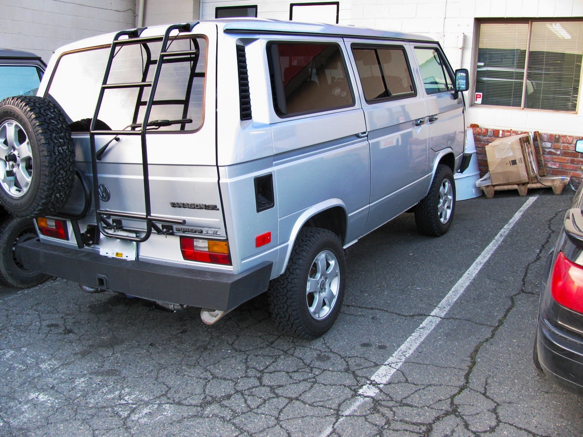
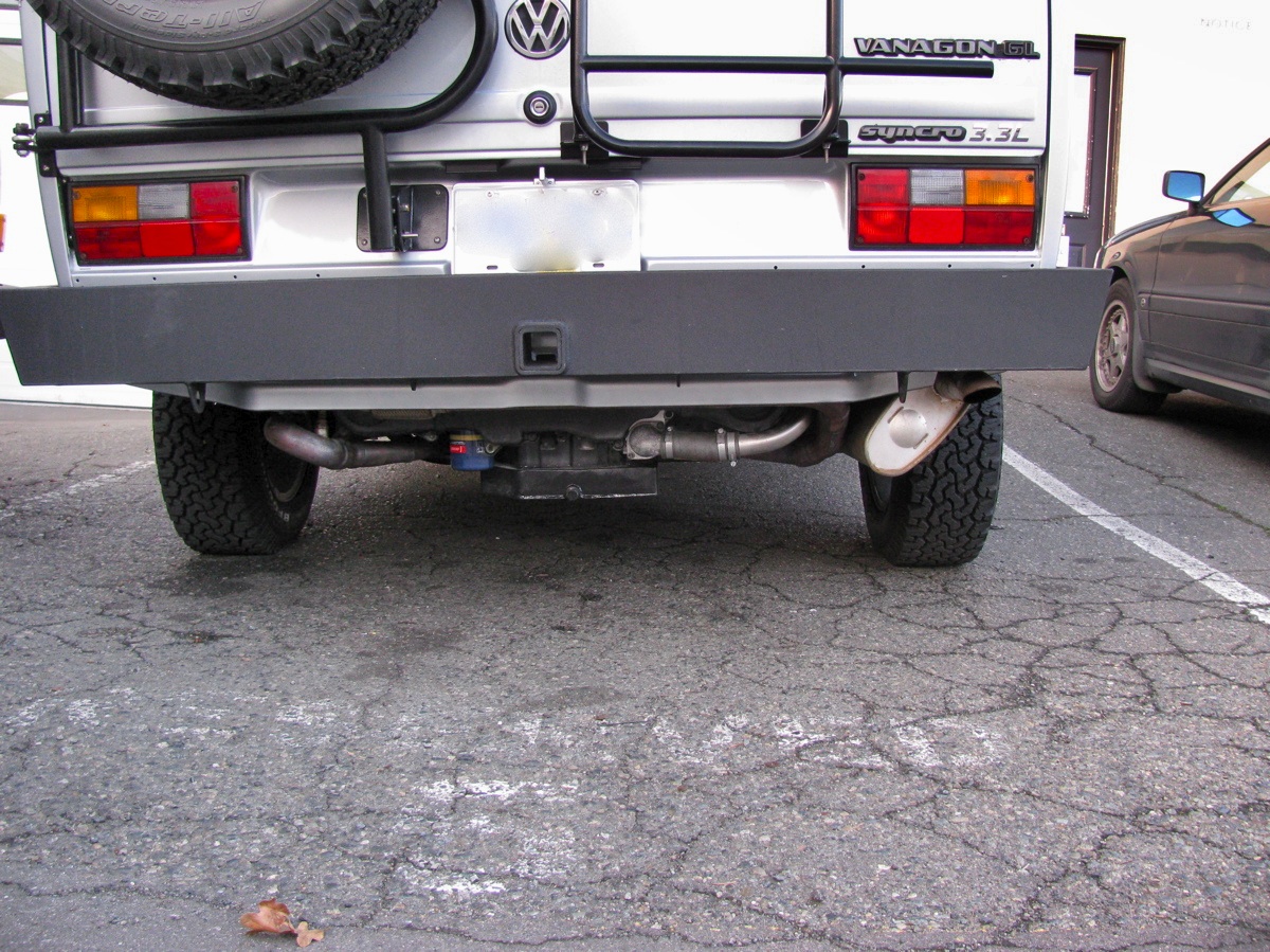
Vanagon – radiator replacement
Last week I swapped new radiator into my friend Simon’s 91 syncro westy. What forced this swap was the failure of the threaded insert where the fan thermoswitch goes. We were trying to install a new switch (old switch was not working properly) and the insert just gave up the ghost.

So Simon left the van at my house and came back a few days later with a new rad and I had the pleasure of doing the install. A bit of background on this van’s radiator, about a year and a half ago we did the thermoswitch replacement, the story is told here. I think I should have nagged Simon a bit more to get a new rad back then, that eroded switch could not have been a good sign.
Removing the rad is a pretty straightforward, if messy, job.
– drop spare and remove clamshell
– clamp off coolant lines
– disconnect wires to rad fan
– remove upper and lower grills
– disconnect thermoswitch (obviously I did not need to do that!)
– remove the (probably rotten) cardboard wind deflectors from around the rad
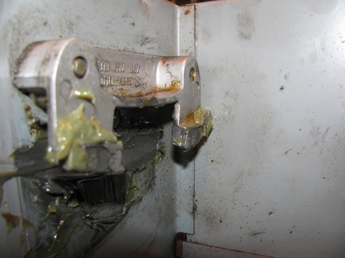
– I found that removing the passenger side “L” bracket ( 2 X 13mm bolts) first allows you to get access to the spring clamps on the coolant lines, leave the driver’s side bracket untouched for time being to hold the rad in place. Passenger side bracket removed:

Note: see the rubber washer on the plastic”tit” between the coolant hoses? There is a tit on each corner of the rad, the upper ones fit into holes in the van body, the lower ones into holes in the “L” brackets. Don’t lose the rubber washers. Well, go ahead, lose them. Garden hose washers would probably make an ok substitute.
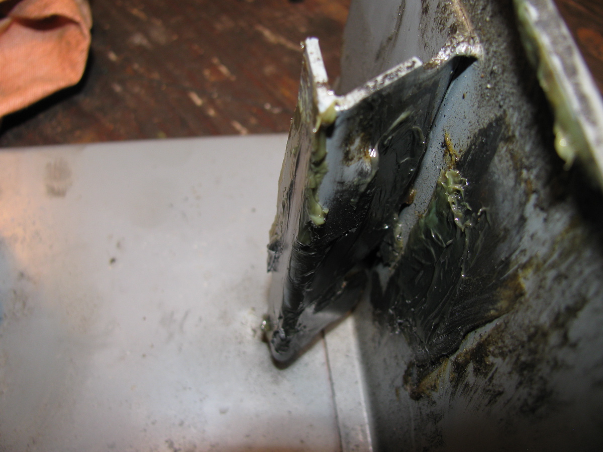
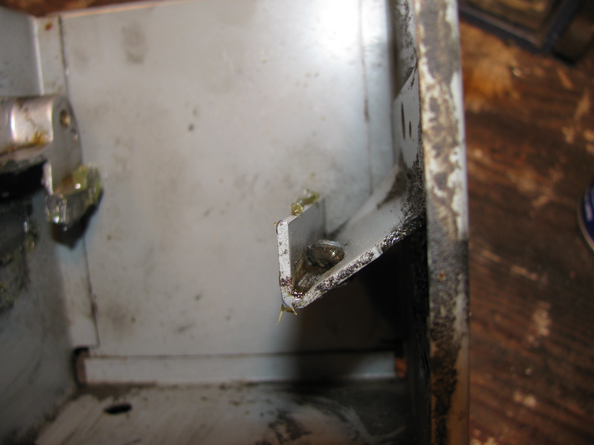
Driver’s side bracket still in place (pic taken before I removed the lower cardboard wind deflector):

– cut or undo any cable ties holding up the coolant hoses or the fan wiring so that the radiator will not hang up when it comes down.
– remove the driver’s side “L” bracket. Careful, the rad will drop down.
– drag the bugger out from under the van and swap the fan and shroud ( 10 mm self tapping screws) over to the new radiator.
Installation is harder than removal as you have to fight gravity and get those upper tits into the holes while lying on your back below the van. A helper at this point would be, well, helpful. Don’t forget that the driver’s side “L” bracket interferes with the spring clamps on the coolant hoses, and don’t forget to push up on the “L” brackets as you tighten the bolts to make sure the rad is seated tightly.
Now the fun part, Sawz-All plus Simon meets the old rad. He cut it in half then cut the plastic end caps off. We found the remains of the threaded insert and a whole lot of gunk at the bottom of the rad. Remember it is a 2-pass rad, hot comes in and directed by end cap up to upper half of rad, then it goes across from passenger to driver’s side and down the other end cap, then back across lower half. The junk was found in the lower, passenger side, ie just before the exit and just below where the thermoswitch (rad fan) is installed.


Note: I drained all the coolant and flushed the system on this van, then recharged with fresh coolant. I found bleeding the Vanagon and Subie EJ25 combo to be much more of a chore than stock or my old inline four in my ’82 westy.
Vanagon – local meet November 2011
A hardy few met at Beaver lake today. All Westies (if I can include my conversion), three syncros and two 2wd. One Tdi, one Bostig, one 2.5 Subie, and two stock wasserboxers. Was fun to kibitz and see each other’s vans.
Vanagon – D15 connector issue
Posted by albell in syncro, vanagon, vanagon mods on November 2, 2011
Yesterday, driving the ’86 syncro, going down a long hill and the van died (noticed when throttle re-applied). Pulled over and it started back up after a couple of tries, funny I thought. Got to my destination and parked for a few hours. Then I tried to start the van and it turns over and catches for a second then dies. Try again, same, then subsequent tries has it turn over but no start. Noticed no fuel pump noise with ign on (and my van does cycle fuel pump with ign on.)
Looked in the engine compartment with ign on. No hum from idle valve. Pulled the fuel pump and ecu relays and replaced with new (during which I jumped contacts and did get fuel pump to run). No change, no idle valve hum and no fuel pump, and no start.
Then I pulled cover from fuse panel and pushed on fuses and generally jiggled panel. Fuel pump cycled on, and I could start the van. Drove home with no problems. I suspected the known problem of the D15 connection on the back of the fuse panel. This connector supplies power from ign switch back to engine compartment and can power (depending on van year and VIN) the fuel pump relay, the idle control unit, coil, and the crankcase breather heater. Gets a little muddled in that the crankcase heater was retrofitted to early ’86 vans (and that seems to be the situation in my case). The wiring diagram shown below is specific to my van.

No matter what version you have, the D15 connector is oveloaded. Note in the diagram there is another connector in the “D” plug that is on same current path as D15. This unused connector, D23, is a bigger Molex than D15. Today I pulled the fuse panel down and removed the “D” plug. D15 looks like it has overheated.

I couldn’t find a spare larger Molex connector to make the switch over to D23, but I did put a new connector on the black wire to D15 and spliced in a pigtail so that when I get the right connector I can plug in to D23 (see the unused larger hole at the bottom?).
Update: I did finally find a large female, molex type, connector for that pigtail, and it is installed into D23.
I can’t say for sure that this connection was responsible for my no start problem yesterday, seems likely though.
Addendum: dug up the Samba thread on this subject, worthwhile reading.
Vanagon – syncro viscous coupling replacement
Posted by albell in syncro, syncro specific repairs on October 23, 2011
I pulled the front diff. on the syncro today to replace the old failed (weak) viscous coupling (vc) with a good used one. Dropping the diff. is in the Bentley manual so I won’t describe that part except to say that it takes a bit of wiggling to get it out. I used a motorcycle lift as a transmission jack. Once out I set it on a container to drain.

See the dark dirt on the input end? Looks like the oil seal there is leaking, need to attend to that. Once most of the oil drained out I humped it onto the bench, just to look at it.

See the speedo drive sticking out? Then it’s on to the floor and off with the 13mm bolts holding the skinny end on.

Some tapping with soft faced hammer to break the seal and it comes apart.

Yup, that’s the vc sitting there, with a spacer on top.

The vc just lifts right off, exposing the speedo drive gear on the pinion shaft.

Closer view of speedo gear.

With the case separated I drained the remaining oil, applied some sealant to the mating surfaces, put the new vc on the pinion (and didn’t forget the spacer) and the skinny part of the case re-installed and torqued down. All well and good, refill with oil in the morning. Now the interesting bit. I had to take the end plate off the old vc, I was dying to see the inside first hand. The big C-clip came out easily.

That end plate should then pull out, but it wouldn’t come. I thought maybe if I drained the vc and also run an awl around the edge of the plate to remove gunk it might help matters. The silicone flowed out, not as viscous as I have seen in those German videos showing refills, and looking like it might have some gear oil in it. BTW, didn’t smell bad.

Got the end plate off.

Removed the C-clip on the shaft (barely visible in above pic) and pulled the first two plates out to look at the adjacent surfaces. Need any more evidence that the plates do come in contact during hump? Upper plate in pic has been flipped over.

Close ups.


Accepted wisdom is that a weak vc is due to the silicone fluid leaking out. One could expect an O-ring to fail with time, but what I found was something else. I had a look at the X-ring that seals around the central shaft (there are two, one on each end, the one shown is in the end plate). It appears that the X-ring is twisted in the groove, look.

Out it comes, yes, it is twisted.

Another view (damned cat hairs, get everywhere).

This surely must have happened at the factory, a lip of the X-ring getting caught on the shaft during assembly. Tsk, tsk, Steyr-Puch.
Addendum: I’m assuming the vc had leaked some fluid, but even with that folded X-ring I have no proof. The “dirty” fluid from the vc could be gear oil contaminated or it could be metal particles from the plates. Perhaps I can use a magnet to determine?
Vanagon – A viscous coupling
Posted by albell in syncro, syncro specific repairs on October 12, 2011
Thanks to good friend Simon, I have, in my hot little hands, a used viscous coupling. It might be on its way out, getting aggressive after a long hot drive, but it will be great for me this winter.
Here is a view of the front, the front differential end.

A couple of things to note:
-the punch mark up there on the rim between the circlip ends. It aligns with the casting ridge between that screw port and the rim.
– the paint on the screw ports and on the circlip ends.
Closer shot of the punch mark on the rim

The punch marks and the paint on the circlip must have something to do with registration on end cap for balancing. I doubt they were there to help rebuilders, but rather I am guessing the unit was balanced before filling (there are spot welded balancing tabs on the side of the body) and the marks are there to be sure it went back together balanced.
Here is the other end, the one closest to the propshaft.

Coming soon, the install, and perhaps (if I can get my act together) some sort of bench test of the VC.
Vanagon – steering arm boot and radius arm sleeve
Posted by albell in syncro, syncro specific repairs, vanagon on September 19, 2011
It all started so easily, replacing a torn steering arm boot (same boot in all Vanagons).

I figured if I removed the ball joint end of the arm from the steering knuckle I could pull the boot off over it and and not change the arm adjustment (toe in). Out to the ball joint at that end, castellated nut with cotter pin.


I pulled the cotter pin and unscrewed the nut, then screwed the nut back on backwards to protect the threaded end, gave the steering knuckle around the ball joint a couple of good raps with a heavy hammer, then rapped upwards on the nut and the joint popped free. Nice when it happens so easily.

The boot was held on by 2 metal clamps (Oetker?) and I snipped the crimped part with some wire cutters and then pulled the boot out towards the ball joint.


That rubber doughnut on the arm locates the outboard end of the boot. The new (well, used one I had in my parts bin) went over the ball joint and up to the rack. Oh, I did put a bit of grease on the exposed ball joint on the inboard end of the steering rack. I used cable ties to secure the boot the the rack and the rubber doughnut.

Now the interesting part, while under the van I decided to have a look at that side’s radius arm rubber bushing and inner sleeve. These parts do wear out, and the sleeve rusts. I undid the drop link from the sway bar to the radius arm, the 19 mm nut at the out board end of the radius arm (inner bolt not touched, to keep the castor unaffected), and the 3 X 19mm bolts that holds the radius arm to the steering knuckle. As suspected, the sleeve was badly rusted and the bushings shot. The subframe hole also was rusty, but still sound underneath. Pretty well the same set up in 2wd Vanagons, its just that the syncro has that front subframe. Neil has a great write up on fixing his damaged radius rod mount on a 2wd Vanagon.


So I have to get new bushings, but right now I decided to make a new sleeve. The dimensions of the sleeve (found on this Samba thread) are: 56 mm long, 25 mm OD, 19mm ID. I did not have any pipe that was close to those dimensions but I had some stainless steel shafting from the scrap yard. It’s not the most efficient way of making a sleeve I admit.

etc…

I could have made a few pot scrubbers with the swarf. The finished sleeve beside the rusty one (btw, the stock sleeve looks like welded tube, and only rusty on the outside).

I slathered everything with a homemade Waxoyl concoction and put it all back together. I’ll order some new bushings.
Recovery Gear
Amazing what you find when you start cleaning up the workshop. If I lash this to the front of the van will it get me in tight with the Landrover guys? 🙂


Vanagon stock wheel and tires
German pdf listing the stock wheels sizes and tire specifications from the factory for 2wd, syncro, and 16″ syncro.
Vanagon syncro – transmission oil change with complications – Solved!
Posted by albell in syncro, syncro specific repairs on July 1, 2011
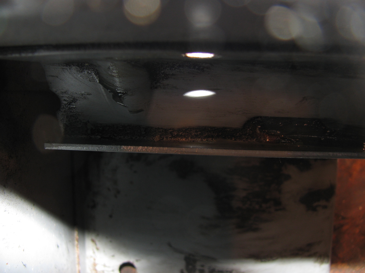
A week and four (!) attempts later I finally have the leak fixed. It’s a tale of woe and I guess you could say blindness on my part. When I re-installed the cover plate and noticed the drip at one of the lower cover bolts I assumed the leak was coming from a poor seal at the plate. So I drained the oil and left the cover plate off overnight. Next day I cleaned the mating surfaces well with brake cleaner and used Permatex grey RTV on the sealing surface. Filled the transmission and it still leaked, a small drip at one of the cover plate lower bolts. Now I was peeved. Emails to Daryl at AA Transaxle gave me some confidence, he suggested that I make sure that the cover plate was flat and that the 6 mm socket head bolt under the cover plate was good and tight. So once again I drained the transmission (cover plate off again) overnight. Next day I set about making sure the cover plate sealing surface was flat. I tried flat filing but even with the file loaded with chalk, aluminum filings would ball up and scratch the surface.

So I switched to lapping the cover on a bit of granite using a couple of grades of carborundum grit and WD40 as a lube.
Coarse grit:


Finer grit:


You can see a few larger scratches, must have had some coarse grit carried over. But that doesn’t really matter in this situation, what I wanted was the the cover plate sealing surface to be flat.

Back at the transmission I removed the old silicone sealant which what I thought was squeeze out from the original install of the cover plate, right adjacent to the cover plate hole rear side. This was where I was blind, I should have thought more about why there was so much clear silicone there. I also carefully filed what I thought were slight ridges around the bolt holes on the cover plate sealing surface. Here is an example (you might guess that I was grasping at straws here):

Filed:

As another example of me being gormless, I even smeared some RTV on the area where I removed the old silicone caulk on the case seam. Why did I not put more on and further up the seam? I don’t know.

Cover plate was caulked and put into place.

I was generous with the caulk – well that’s what I have been told 🙂
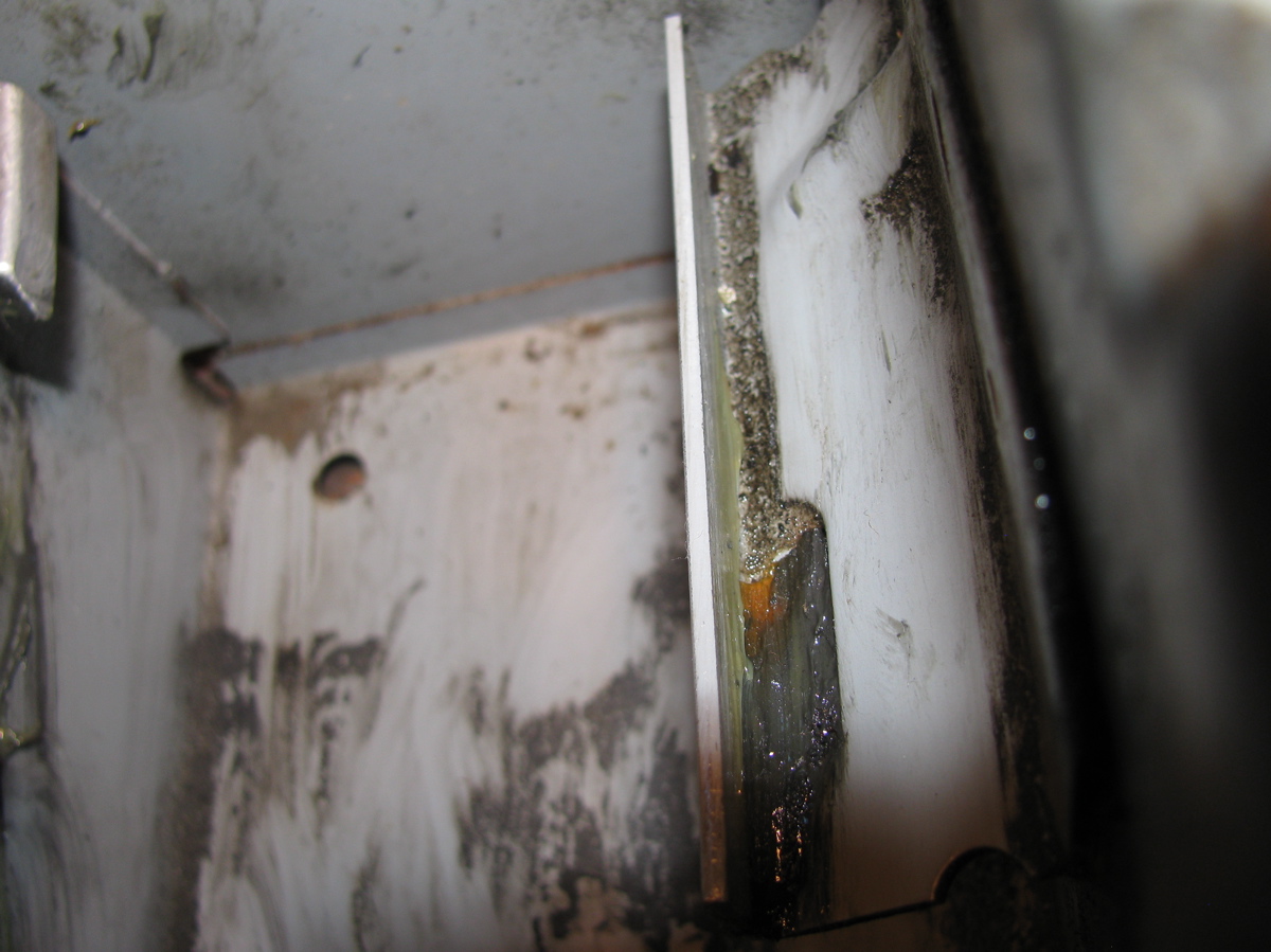
I let the stuff cure for about 5 hours before I filled the transmission with oil. Can you guess what happened? Yes, still a little drip. Chagrin does not adequately describe my feelings at this point. I went under the van and looked carefully and I noticed oil seeping out from the top edge of the little it of RTV I smeared on the case joint (pictured above). If I put a corner of a rag on that spot the drip at the lower bolt would stop. Why had I not noticed this before. More info from Daryl and a sinking feeling that I might have to pull the transmission and reseal the case joint. But I decided to make one more attempt. Again, an overnight drain of the oil and this time I scrubbed and degreased the case joint all along the side of the cover plate hole. I bought some of the expensive RTV sealant, “The Right Stuff”, it had a few good recommendations and is a fast curing goop.
Picture here of the cleaned area (cover plate sealing surface was later cleaned of the old grey Permatex):

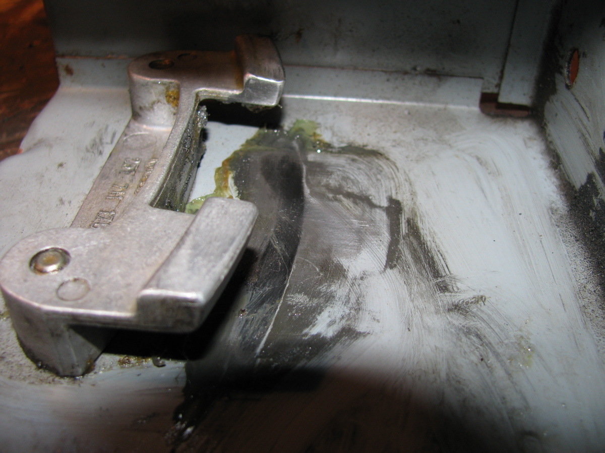
I also gave that socket head bolt another bit of twist. Then I smeared on sealant over the case joint, and on the cover plate sealing surface, not very pretty:

I let the stuff cure for a few hours then refilled the transmission and went into town on errands. I was not optimistic about success, but I’ll be dammed if the damn thing is now sealed tight! One day later and it is still dry. I’ve come to the conclusion that the original silicone caulk that I removed from the case joint area was put on to stop a leak. I bet it was done when the transmission was rebuilt.
I learned a few things from this fiasco. Apart from being more observant I discovered that when putting on the skid bars/plate on the syncro, install the bolts loosely until all are in place, before tightening. That makes it so much easier. I also found that my Snap-On transmission wrench (17 mm hex) was awkward to use on the fill plug (but very good on the drain plug) so I cut a section off my 17 mm allen key and used the short bit on a 17 mm socket, and even better, on my 17 mm ratcheting spanner.


Vanagon syncro – transmission oil change with complications
Posted by albell in syncro, syncro specific repairs on June 24, 2011
A very brief overview of a transmission oil change in my ’86 syncro. I had not changed the oil since I bought this van almost 2 years ago and I noticed a very slight oil leak/seep at the bottom edge of the reverse gear cover plate. I figured it would be worthwhile when I had the chance to drain the oil and look at the cover plate. I bought some regular run of the mill 80/90 wt gear oil with the idea that I would put in the fancy gear oil later after I fixed the cover plate leak. As it turned out, this was a smart move.
The oil fill port is on the right hand side of the van just above the shift linkage rear bushing. The drain port is near the rear near the midline. Important to first see if you can unscrew the fill port before trying the drain port. To get at the fill port easily I found it best to remove the rear skid plate/bars; 2 X 17 mm nuts and bolts at the engine carrier bar, 2 X 17 mm bolts and 2 X 17 mm nuts and bolts at the forward end of bars( actually there is a 15 mm nut on the upper left hand skid bar mount), and to detach the shift linkage rear bushing housing; 2 X 13 mm nuts and bolts.
Kinda silly picture of skid plate out.

Oh, I should mention the tools I used to remove the drain and fill plugs. A 17 mm allen key, and a nice Snap-On tool with 17 mm hex. I needed the allen key to help the Snap-On tool at the fill plug, there was not enough space to fully swing the wrench (you know what I mean).

And more obvious advice: clean out the hex recess in the plugs with dental pick, toothpick, compressed air, whatever. Ya gotta have the wrench make a good fit. I squirted penetrant/rust buster on the plugs, more out of habit than expecting that the damn stuff actually does anything. Next pictures shows the fill plug (shift linkage still up in place) and the wrench in in the plug, riveting story eh?


Thankfully the fill port plug unscrewed with no problem. Next, on to the drain plug. The wet spot is the penetrant fluid stain.

It too came out with no trouble. The magnetic plug had a bit of fuzz on it, but I think this is a pretty normal coif.

While the transmission drained, I removed the weeping cover plate. It seemed to be leaking at the bottom edge.

Plate off, evidence of silicone caulk as a sealant.

Close up of the bottom corner that I suspected the leak was coming from. No smoking gun that I can see, minor scratches, almost a crack like line there though, no?

At this point I was advised by my son that I need to drive him to some sort of “date”, grrr. I should have let the transmission drain overnight and degrease the mating surface of the cover plate before applying rtv silicone and re-assembling (as per Daryl of AA transmission’s advice). So I slapped on the the silicone and the plate, and set about filling the transmission. I made a fill hose with some pvc tubing and a funnel.

All filled and the skid plate back on, the shift linkage re-installed, and the damn cover plate leaks more than before. So, tomorrow I’ll do it all over, this time properly letting the cover plate area drain and be de-greased. Daryl also advised flat filling the cover plate flange to make sure it is flat.
Vanagon syncro aux. back up light installed
Posted by albell in syncro, vanagon, vanagon mods on June 1, 2011
I gave up on making an adaptor for the chrome light housing and decided instead to make one for a rubber housing, here it is.


Made of black polyethylene, kinda clunky looking. Jony Ive does not live here. It does seem to work though.


I led the power and ground wires through one of the holes in the rear valence, up over and well away from the muffler, and through a grommeted hole in the heat shield. I do wish there was a better route. I used one of those black plastic electrical box to house the relay.

I used wire I had lying around, not conforming very well to any colour code. I did use a little bus, power is on the right, and ground on the left. I mounted the box onto the plastic “bulkhead” that the air intake snorkel connects to on the right hand side of the engine compartment. I tapped into the black/blue power wire feeding the right hand side back up light to provide the signal power for the relay.

I also put in an old back up beeper I had on my ’82 westy. I was a good thing to have when my son was young and I got used to it, so now it’s on the syncro, just lying in front of right hand side tail lights.

I took power from the alternator stud – NOTE – I have not installed in inline fuse on this feed line yet, one DOES need to be installed. I led a ground to one of the alternator housing screws.

Gack, I need to buy black cable ties. Tested, and works (beeper too).

Vanagon syncro aux. back up light bracket
Posted by albell in syncro, vanagon, vanagon mods on May 31, 2011
I want to put an auxiliary back up light on my ’86 syncro but never have found an attachment method I liked. That is until Brett H. told me about how he did it, so all credit for this bracket idea goes to him. I used scrap stainless stock I had in the workshop (hence the double holes shown) and I have an old bumper that I could do trial fittings on. Pretty simple bracket, easy bends.

It bolts to the bumper using one of the holes that the plastic clips on the rubber “rub strip” attaches to.

The lamp housing is one of a set I found at the Salvation Army some years ago. I had one on the front of my old ’82 westy, fitted with a 250 W aircraft lamp. The test fitting on the old bumper looked ok.

It is possible to attach the bracket while the bumper is on the van.

I enlarged the hole that the plastic clip was set into so that the rub strip would fit over the bolt.

The rub strip fits back on quite well, I was lucky with the hole enlarging, it seems to grab the bolt head.

Attaching the lamp to the bracket showed that I need to tweak things a bit, light is pointing slightly down. I’ll make an adapter tomorrow and show the electrical part of the install. Oh, in the pic above, the bracket is to the right of the license plate (seen on the left).
Vanagon syncro – NOS shifter box
Posted by albell in syncro, syncro specific repairs on May 30, 2011
Courtesy of Bill M.

Vanagon syncro gear shift lever maintenance
Posted by albell in syncro, syncro specific repairs on May 29, 2011
R. Jones pushed me into this, he wanted to see how it all goes together. I’ll go through it on point form, pictures and text. Bentley has an exploded view and instructions for back up.
On the way out to the workshop I noticed a cool spider on a leaf of one of the jade plants we put outside for the summer. Got a quick snap before it moved. If you want good pics, head to A. Gordon’s Wordlessme.

Back to the job, first unscrew gear lever knob and pull off the rubber shifter boot. Then mark the position of the upper plate on the lower plate. I scratched circles through the two holes in the upper plate.


 No need to remove the two 10 mm nuts you see there right now, we will be taking the two plates out together. Then it’s under the van to drop the spare and remove the shifter box, four 10 mm nuts and washers, careful, they drop easily 🙂

Box removed

Now remove the vertical from the horizontal between the “ears”. It’s a 10 mm stover nut and a washer on one side, and a 13 mm headed bolt on the other.

Now you can get back into the van and pull up the plates and shifter, and take it to the bench for disassembly.

There is a set screw on that metal collar on top of that spring, hold it tight as you back the screw off and remove collar and spring. The shift lever will slide out of the housing assembly. Look at the “T” end of the lever, remove the 2 plastic bushings. These are wear items and it would be a good idea to replace them.


I didn’t as I did not have any on hand, and I couldn’t be arsed to make some up. The bolt that rides in there looked a bit worn and I suppose the small amount of play in there does contribute to the overall feel of the shifter. Here is the bolt back in the bushings.

And the wear.

Back to the other parts, now you can remove the two stover nuts holding the upper and lower plates together, you did mark position of the two plates first right? The white plastic collar on the underside of the upper plate is pried out.

Then the entire inner workings, rubber collar and all, can be pushed out from top to bottom. It might be tight, but palm pressure is enough to do it. Careful not to break the upper plastic.

The two white plastic bearing shells can be pried out of the rubber and that will allow an internal spring to sproing things apart.


Now clean all the parts.

Reassembly is pretty straightforward, first squeeze the split shells into the rubber collar, might be a bit of a struggle.

Then the one inner bearing with the protrusion is pushed in from below until it snaps into place. Good time to put a little grease on the rubbing surfaces. Not too much, Bentley makes no mention of lubricating the plastic assembly and I have seen some that are caked in grease and dirt, so it is probably best to go light with the schmalz. Do, however, put a dab of grease on the gear lever where it goes into the plastic assembly and in the bushings on the “T’ at the end of the lever. Note that the rubber collar has a “top”, the little ridge, see? Sorry about bad focus in the next couple of pics.
 Then put the larger of the two springs on.

And press the upper bearing into place, again it snaps in. The rubber collar allows the split shells to spread.

This assembly is now pushed into the upper plate.
 Followed by that plastic collar.
 Put the upper and lower plates together and secure (in the right place using your marks) with the two 10 mm stover nuts. I risked Zinc and or Cadmium poisoning and buffed up the shift lever. The lever is inserted into the bearing assembly, the spring put on, and the collar locked down in place (there is a dimple on the shaft).

Out to the van, and pop the gubbins in.
 Then under the van to connect the shift lever to the ears using that bolt and bushing arrangement. Bolt the box back on and put the spare tire and tray back in place. Back upstairs and rubber boot and shift knob back on.
 That’s it. Oh, I suppose I should have mentioned that you can get replacement plastic parts for the assembly from the usual suspects, Van Cafe, Go Westy, Bus Depot etc. I re-used the old parts, they seemed to be in OK shape.
Vanagon syncro front shifter box pics
Posted by albell in syncro, syncro specific repairs on May 28, 2011
For Doug M., wanted to see the wear patterns. Looks in good shape for being almost 25 years old and god knows how many shifts.
Vanagon syncro shift linkage – rear, and a glance at the front
Posted by albell in syncro, syncro specific repairs on May 22, 2011
I’ve been noticing that I sometimes have a little difficulty shifting into 1st and 2nd. Spraying grease on the exposed wear points on linkage under the van makes the difficult shifting go away for a while, so even I got the message that it needed some attention This diagram shows the linkage, my van has neither the shift linkage protective tube, nor the rubber boots protecting the rear bushing.

Another difference is that as well as the roll pin that secures the horizontal linkage to the vertical link right at the transmission, my van also has a horizontal bolt and nut securing the two. The linkage at the rear comes off pretty easily, except that the skid rails on the syncro does restrict access to some nuts and bolts. The roll pin is tapped out with hammer and small drift from the inside of the vertical link, that link drops from the ball link which is attached (13 mm nut) to the shaft coming out of the transmission. On the bench, the manky, dirty bunch.


Then all cleaned up.

The brown ovoid shaped bushing was packed inside with a mixture of old grease and grit, took a few minutes to get that clean. The roll pin is worn, I think I should get a new one ( have a spare bit of linkage so I can get the right size at the shop).

Then it’s grease them up and put it all back into the van, with a spritz of Fluid Film. Not really happy about the rubber boot that covers the transmission selector shaft. It does grab onto a ridge on transmission, but outboard end of it doesn’t seem to attach to anything. You can see a glint of exposed shaft in the pic below.


Shot of the linkage U-joint, which seems/feels pretty good, and the forward bushing which takes a bit more effort to get to.


No road test done to see if the shifting has improved, but parked, it goes into all gears nicely.
While I was in the mood, I had a look at the linkage/joint right under the gear shift lever. You know, hidden by that box above the spare tire. I had been reading this thread on the Samba and was curious.

The plastic ears are in place, and not too badly worn. Trust me, you can’t really see because to the grease.

Cleaned off the old grease and put new stuff on.
Vanagon syncro left hand side transmission mount and breather line
Posted by albell in syncro, syncro specific repairs on May 12, 2011
Still buggering around wondering how to raise the front of the transmission to reduce the output flange downward angle. I supported the front of the transmission and pulled the left hand side mount off. The mount on the other side is much less accessible, coolant lines restrict access. I guess I have to say that this is pretty dull blog stuff. Maybe it helps other folks doing the same thing, but mainly I am treating it as a journal, recording what I have done and reminding me what to do if I have to do it again.
So the rubber mount there is attached to a bracket which is bolted to a beam under the van, and to an ear on the transmission.

It is hard to get a wrench up to the nut on the top of the rubber mounts, but an angle head ratchet wrench (17 mm) can be squeezed in there, and the other end attacked with a socket. I found that loosening the three 13 mm bolts that hold the bracket to the beam allows the ratchet wrench to get up there easier. One funny thing, the EKTA-like diagram above show those bolts coming in from above, they don’t. So the rubber mounts and bracket were pulled out. Here is the bracket on the bench.


I sprayed some white paint on the rubber mount bolt and transmission ear just in case the transmission shifted aand I had to get things back in the right spot. As it turned out, the other mount held things in place.
I compared the rubber mounts, upper and lower (above and below the bracket). The upper one is marked with “U”.

Looks a bit collapsed, saw the same thing with the front diff. mount. The bracket was a bit rusty so I scraped off the rust and slapped some POR on it. While the paint was drying, I had a look at the part of the transmission that was exposed with the mount removed. I found the transmission breather hole which, in the syncro, has a plastic tube leading somewhere higher so that the vent won’t take in water if wading in the van. Sometime in the van’s history the transmission was rebuilt and the breather tube was reconnected to the hose barb on the transmission via a short length of rubber hose. It came off too easily so I used some clear PVC tubing to connect it (heating the stock tubing with heat gun and trying to get it on the hose barb was not a success).


It really is a tighter fit than it looks in the picture, I’m confident it will stay in place. I reassembled the mount, with the lower rubber now on top, and had a few minutes of “quality time” re-installing. I did not succeed in finding any new ideas on adjusting the transmission angle, but I am glad I got the breath line better secured.
PS I also re-installed the “new” propshaft I was babbling on about a few posts back, I had replaced one of the U-joints since. Well, the upshot of all of this was that the driveline vibrations are pretty well gone. Still a very, very slight vibe at 50 kph, but it is really acceptable.
Vanagon syncro propshaft comparison
Posted by albell in syncro, syncro specific repairs on May 9, 2011
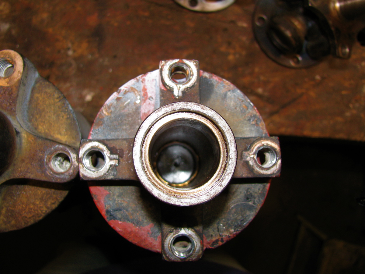
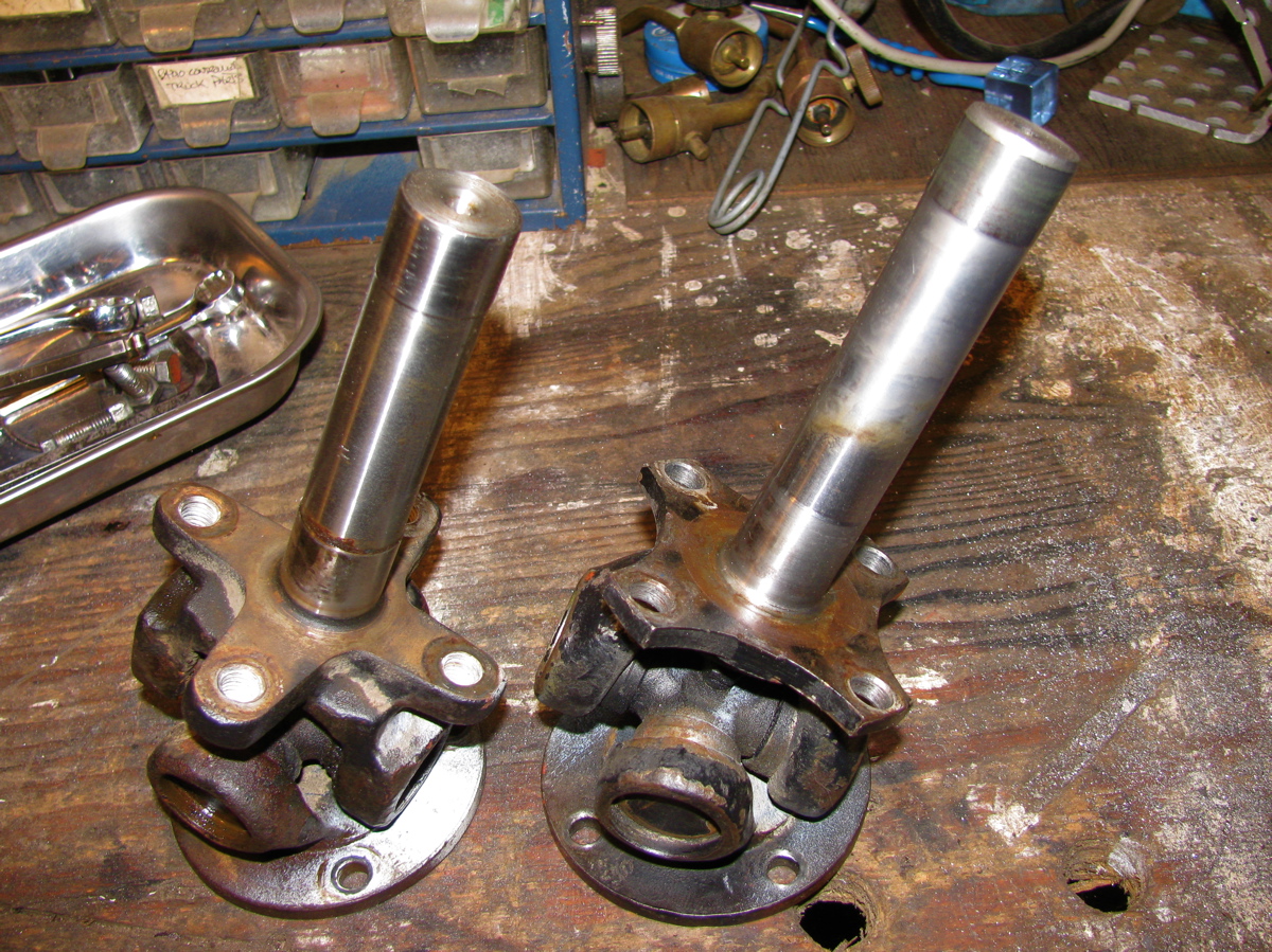
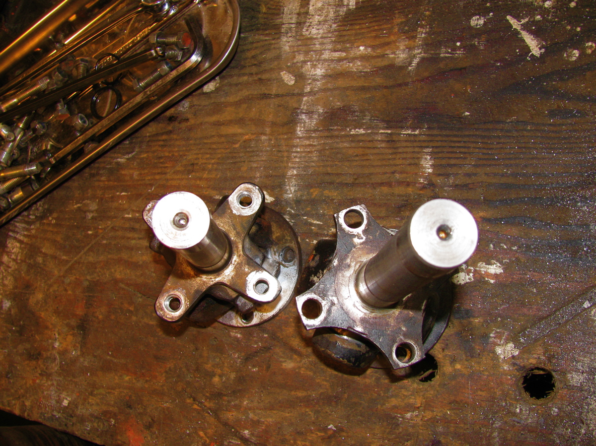
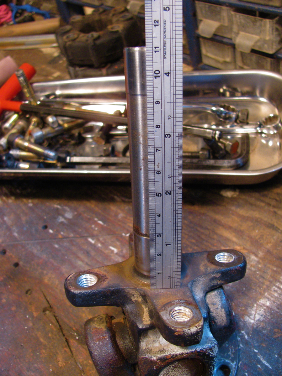
Took apart 2 stock propshafts. The rusty red one is an ’86 model, the black one is from a later van (I don’t know the year). You can see that there are a few minor differences. One important one is the machined end that houses the internal bushings. Note the thickness of the internal bushings, the newer shaft has much thinner bushings. Both units have shafts that are the same diameter so it’s the bushing housing that is a smaller diameter in the newer shaft. Also the shaft lengths differ, the older one being longer. The newer shaft has the o-ring in a groove, the older one has a rebate to hold ring.
Some more trivia:
1. the black (newer shaft) had one U-joint that looked stock and one that had a blanked off grease nipple. I am assuming orig. U-joint was replaced
2. The rusty red one, from my van and I am confident that is stock, does match the diagram I posted in previous blog entry. The black one does not match in some details.
3. both internal shafts are same diameter
4. overall length of shafts differ by a couple of millimeters. The black, (newer), shaft being shorter.
5. all the socket cap screws are the same
6. I haven’t found, and this does not mean none exist, any vw part number on both shafts
7. giubos are identical
8. the part of the joint that mates to the trans/front diff, on both shafts are as identical as machined sand cast parts can be
9. the diameter of the propshaft proper is pretty well identical on both shafts (3.155″)
10. both shafts assembled with U-joints out of IN phase


Giubo end of Vanagon syncro propshaft
Posted by albell in syncro, syncro specific repairs on May 8, 2011
I played around with a spare propshaft that I got the other day (thanks again SImon). I installed it in the van as is and it did have a vibration at around 50 kph. Wasn’t a huge vibration, but it wasn’t acceptable. Believe it or not, but it felt like the vibration was to the rear rather than the front. I took the shaft out and set about taking the giubo end apart. First thing noticeable was the U-joint had slight axial play in one of the crosses. I took off the circlips at that joint and they measure approx 0.050 in thickness. I installed a pair of 0.060 circlips and that eliminated the play. The ears of the joint look a little beaten. Also, doesn’t look like the circlip is fully in the groove does it? But it is… I think 🙂

I still could detect play at that end and guessed it might be from wear in the internal shaft and bushings. So the giubo and end u-joint had to come off.
First, here is a pic of the end of the shaft.

If you look closely you can see the head of a bolt in the inside face of the U-joint. This is to plug a grease nipple port and indicates the joint is not stock. Close up of that area.

Before taking things apart, I sprayed some paint on the works so I could put it all back together in the same orientation.

Then off with the bolts that hold the giubo to the propshaft. The giubo and joint pull out. The shaft doesn’t look too bad on the end.

Then remove the bots holding the giubo to the joint.

That end doesn’t look too bad either. You can see the shaft is thicker in the two spots, that’s where it rides on the internal bronze bushings in the prop shaft. Have a look in the hole in the propshaft. There’s an o-ring in a groove at the end. My other propshaft had the o-ring in a rebate, not a groove.

Now the giubo, sitting roughly in place, and it had washers on either side. Pretty cruddy washers, and my other propshaft did not have them.

With the giubo removed from the joint, I reinserted the shaft into the hole and tried it out for size. It felt pretty good, no slop. So where did that looseness come from that I felt when it was all assembled?
I decided to lube it all up and put it back together. I used a band clamp to squeeze the giubo into shape to let me get the bolts back in to attach joint to rubber.

And same technique when attaching assembly to propshaft.

Well, all assembled (minus those washers) and it feels nice and tight. No play like before. So I put it back into the van and had a test drive. It still has some vibration (again around 50 kph) but it is less. I had to say that didn’t I? Honestly it is better but not what I want. So the shaft is coming off again and I’ll take it to the driveline shop for spin balancing.
Addendum: In the comments Rob advised replacing that U-joint. I agree and I should have mentioned this in the post. I’ll ask the driveline guy to do it this time.
More addendum: Diagram of the end of shaft. Does it look to you like of some sort of cap at the end of the internal tube or is it integral to the inner bushing? I’m thinking the former is the case. Also note that it is a nut and bolt that holds the giubo to the U-joint yoke. In the propshaft above its a bolt, with the propshaft yoke having threaded holes. My other propshaft has same attachment method shown in diagram. No washers between giubo and shaft shown on diagram either. I bet there were some minor changes made to the shaft during production.

Vanagon rear wheel bearing replacement
Posted by albell in syncro, syncro specific repairs, vanagon on April 16, 2011
I noticed some play in right rear wheel (jacking up van and trying to move wheel, 12 and 6 o’clock positions) and a whiny noise when driving which changed in loudness on turns. I figured it was time to replace the bearings. These bearings seem to last a long time but there is a limit I guess. For another good description of this procedure have a look at the English translation of the German IG16 wiki entry. To start here are a couple of exploded diagrams showing all the parts. 
 It makes a lot of sense to take out the axle at same time so that you can re-lube the CV joints and also press the stub axle into the bearing housing on the bench. But I didn’t do that as I was short on time. If you do want to take out the axle, undo the transmission side CV joint when you still have the wheel on the van, unless you are using air tools, so that you can brace the wheel when undoing the CV bolts. First thing is to undo the 46 mm castle nut on the wheel. It’s on there tight (275 – 350 ft/lbs) so you need to do it with the van on the ground and the wheels chocked. Normally I use a 3/4″ drive socket and a long armed drive with some steel pipe as an extension. But this time I tried out one of those “slug wrenches”, I was given one a few months ago. The idea is that (after removing split pin on nut) you attach slug wrench to nut, use a 1/2″ socket wrench drive to apply some force, and at same time whack the slug wrench with a short sledge hammer. Its a bit awkward, the wrench lies close to the wheel so ou have to aim carefully so as to not hit the rim. But it worked, the nut came loose.
  Once the nut is loose, you then loosen wheel nuts, jack up and support van securely, and remove wheel. Then remove nut and the brake drum should come right off easily. Perhaps you might need to back off brake adjuster if the brake shoes hang up on a lip if your drums are old and worn.
 Next step is to undo brake line from the brake cylinder and cap it with a bleeder nipple rubber cap. Then remove the 13 mm bolt that holds the brake cylinder to the bearing housing. Then remove the 2 bolts (15 mm?) from the brake shoe holder at the bottom. I then removed the clip that holds the parking brake line to the underside of the trailing arm so that I could keep the parking brake line attached to the brake mechanism. The brake assembly and backing plate *should* pull off the bearing housing. However, it is located on the housing by one dowel pin on the brake shoe holder at the bottom. The dowel was stuck in there tight and I had to tap it out with a small brass drift and hammer. Don’t use a steel drift to do this, it will mushroom the dowel.
 See the dowel pin below the bolt holes in above pic? Wet area on trailing arm is due to some rust busting liquid I squirted on exposed threads on the 4 bolts holding the bearing housing on to the trailing arm. With the parking brake line detached from trailing arm it is possible to to pull off brake assembly from stub axle and lay to the side on the ground.
  Now remove the 4 bolts (17 mm?) that holds the bearing housing onto the trailing arm, and then the housing should pull right off the stub axle.
  Pretty ugly in there eh? Caked on dirt and some rust. I took the bearing housing to the bench for disassembly.
 The grease seals were stuck in tight, I had to put the housing in the vice and use a longish pry bar to pop them out.
  Above pic shows outboard grease seal removed and the inner race of the outboard bearing removed (it just falls out). On the inboard side, after the grease seal is removed there is a circlip to take care of.
  After circlip is removed the inner bearing can be removed by driving it out with a brass drift from the outboard side. The spaced sleeve in there between the bearings can be shoved to the side so that you can get the drift onto the bearing race. It took a bit of “drifting” to get the bearing out. If you have a press then you know how to do it better. Once that inboard bearing is out, the spacer is removed and then the outboard bearing outer race can be driven out. In my case that bearing was really stuck in tight. I used an old disk brake caliper piston to drive the bearing out, was a lucky good fit.

 There is a spacer in that gob of grease.
  Cleaned up the housing a bit, especially the bearing seats.
 All the parts arranged.
  Inboard bearing greased and carefully tapped in using that plastic headed dead blow mallet. Picture shows bearing started in housing, not fully seated.
  Bearings were tapped in carefully (a press would be better), the circlip inserted in the inboard side, the spacer installed and the grease applied liberally around the spacer, and the grease seals carefully installed. Again, picture shows bearing started, not fully seated.
  Now at this point, with the housing reassembled, if I had taken the stub axle off the van it would be pressed (or carefully tapped) into the bearings. But what I did was take the housing out to the van, slip it onto the stub axle making sure I didn’t damage the grease seals and that the spacer lined up on the shaft, and I pushed the housing onto the stub as far as I could. I bolted the housing to the trailing arm, then I used the brake drum and the big nut to slowly draw the stub axle into place. This method worked well. Oh, before I put the housing back onto the trailing arm I cleaned out the dirt and loose rust from inside the arm and shot a whack of Fluid Film in there.
  Then its a matter of putting the brake assembly back on, re-attaching the brake line (was a pain, I had to loosen the slave cylinder on the backing plate to get the thread started on the union), then the brake drum, big nut snugged up but not torqued, the wheel, and then get the van off the jack stands. Torque the big nut to spec (see diagram at beginning of post for torque specs), split pin installed, lug nuts torqued, and its done. No play in bearing when the wheel was grabbed, and the whine when driving was gone. I’m guessing that most Vanagon owners will only have to do this job once, or maybe twice, in the van’s life.
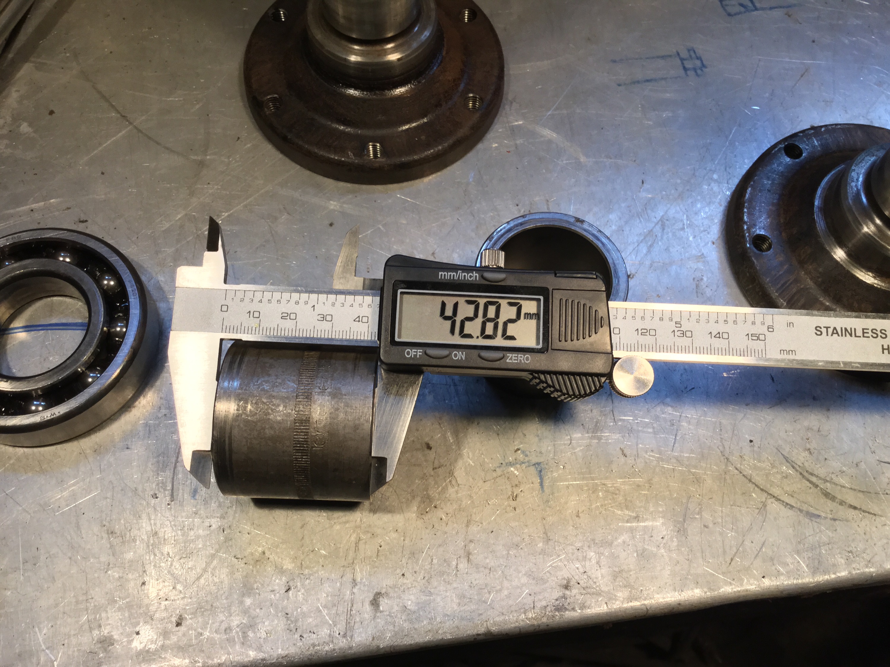
Addendum, April 30 2015, some measurements for Josh 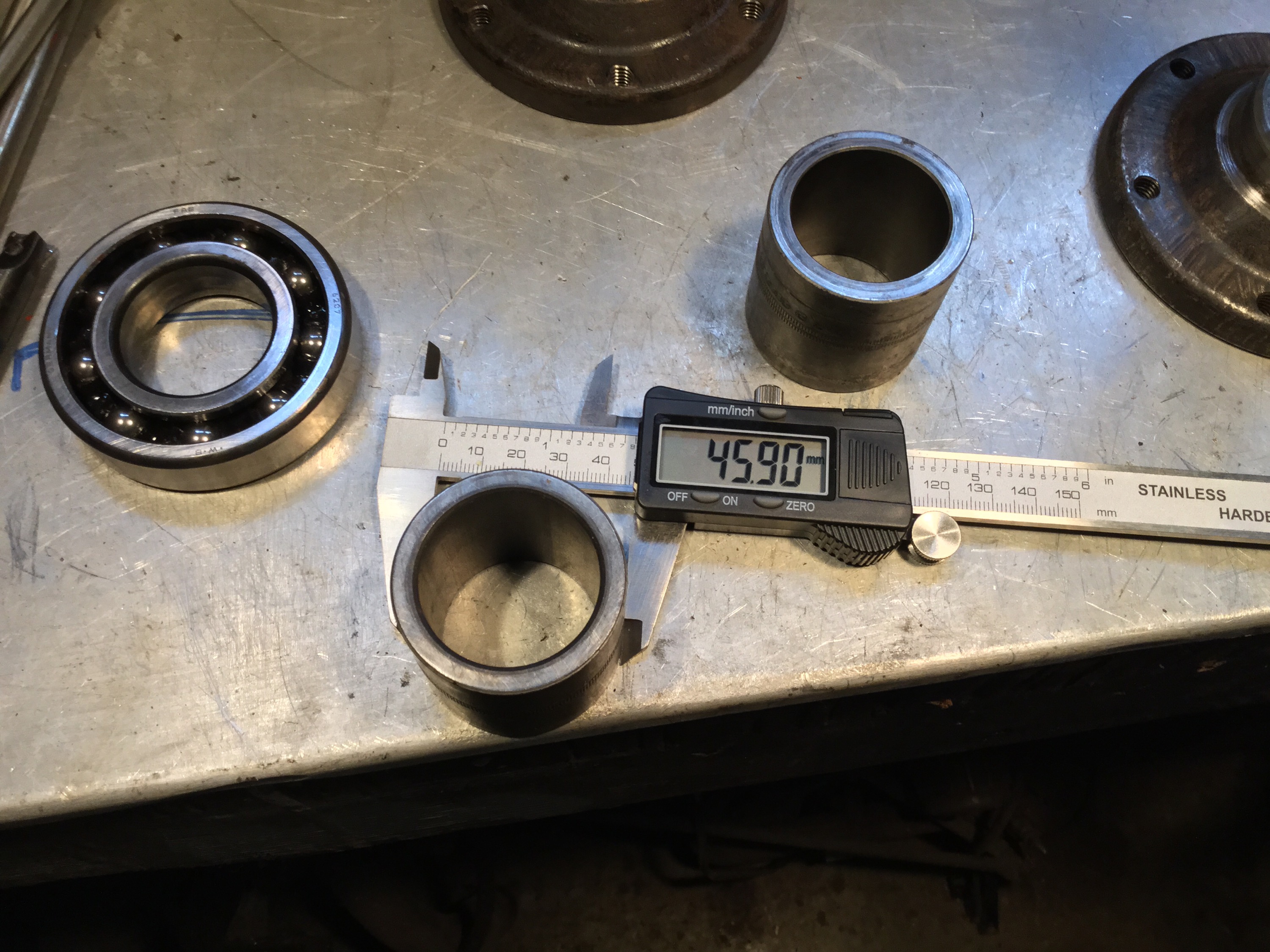


Another logging road trip
This time with visiting Vanagon mailing list pundit David B. We headed to Port Renfrew, then north on that paved road to Lake Cowichan. From there it was logging roads to Nitinat and finally Sarita, a dry sort and booming ground on the south shore of Barkley Sound. Next day we headed west to look at the Pacific at Pachena bay, then north east to Port Alberni and got to see some nice machines behind the scenes at The Alberni District Museum and Historical Society , the Maclean Sawmill museum, and a quick peek at 2 Martin Mars water bombers at Sproat Lake. Then back to Victoria on civilized roads, stopping to look at the big Douglas Firs at Cathedral Grove.
The pics are a mix of mine and David’s.
Quick and dirty Westy table fix
Posted by albell in syncro, vanagon, vanagon mods on March 30, 2011
The old westy table I have in my syncro was loose where the metal base attaches to the tabletop. It used a form of captured nuts in the table top to secure it to the base, and those nuts were loose in the wood, and the holes were chipped and enlarged. I had used some glue to help hold things togther but that was a short lived solution. I think the newer Westy tables have a better system of attachment.
So I set about doing a quick fix. I had some scrap 3/4″ thick PVC sheet:

What was I thinking years ago when I painted that base yellow? I need to repaint it. I cut the PVC to size:

And countersunk some 1/4″ bolts:

Then some PL Premium polyurethane construction adhesive ( the poor man’s Sikaflex) to glue PVC to table:

Now I really do have to get rid of the yellow.
Gordon River trip
Last week my son and I headed out to explore a bit of the Gordon River watershed. The river starts close to Cowichan lake but flows southwest to Port Renfrew and the Pacific. We headed out from home to Port Renfrew then made our way “upstream”. This is the first bridge across the river, near Port Renfrew. Yes, the water was clear and this colour.


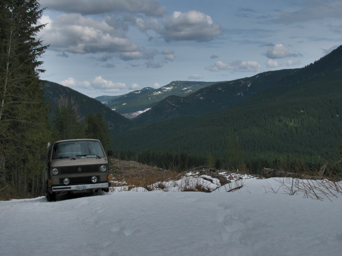
We headed on, exploring various logging spurs to see if we could find a camping spot that had a view, and had some snow. The problem we encountered was that when we found snow on those spurs, it was heavy corn snow, got deepish quickly (20 – 30 cm) and with the steep grades we really couldn’t make much headway.

We ended up at a spot in a recently logged area, about 50 meters below where the snow started.


Well, we had a bit of a view and no shortage of table material.

A word about logging in this valley. I’m guessing most of the watershed, was logged by the middle of the last century. It would have been mostly Douglas Fir and Western Red Cedar, big trees. Now what you see is second growth, Doug Fir, Hemlock, some small cedars. The biggest stumps I saw were about 60 cm diameter. That section in above picture had around 50-60 growth rings. Here are some pic of the recently logged area, showing some old grey stumps from the first cut.


Next day we headed on, again being foiled by steep snow covered spurs, and we decided to try to get to the trail head for Mount Sutton. We found the access road on the north side of the river to be choked with alders. This road starts at the site of the old Gordon River logging camp, which at its peak (1950?) was one of the biggest camps on the island (google map ref). Pretty well nothing remains of the camp now, but if you dig around this site you can find some info and pictures of how it used to be. One strange relic remains, a Mk III Cortina under a fairly large section of cedar log.


You have to be alert for logging trucks, there was about one every 10 minutes.

We headed back west, “downstream” and explored the road that, on the map, leads to the Gordon River Caves. It was another steep and snow covered spur, but we did manage to find a small waterfall and have lunch.


Further west we drove up the north side of the valley, again through logged areas, up steep (measure 29 degrees on one section) spurs, and again foiled by heavy snow. Saw elk tracks though.

We backed down a few meters and found a room with a view.

And some old wolf scat.

It started to rain that night, and the next day. We drove east, “upstream” and came out to civilization near Honeymoon Bay at Cowichan lake. One benefit of traveling on active logging roads is that they are graded often.

It was a fun trip with a few more dents added to the syncro.
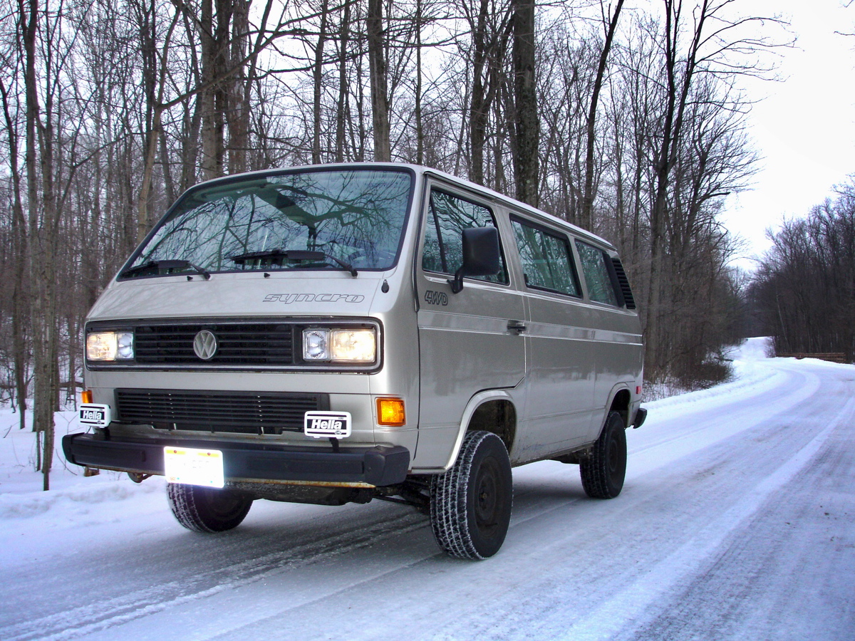
Syncro and Ohio winter
Brett H. sent me this picture of his syncro. Its a good looking van, must ask him about the aux light mounts.
Vanagon syncro propshaft balanced – verdict
Posted by albell in syncro, syncro specific repairs on February 16, 2011
As I mentioned a couple of days ago, I had my prop shaft balanced and I finally have it installed. I drove about 10 km with the front diff. mounts loose to allow it to “settle in”. Today I tightened them down and I can report that the propshaft is pretty smooth. Of course your kind of hyper vigilant in this sort of situation, and I can feel a very very slight vibe at around 60-70 kph, a little like having deep lugged tires. I’m happy with the result.
Vanagon heater hose insulation
Posted by albell in syncro, vanagon, vanagon mods on February 15, 2011
While I was under the van installing the newly balanced propshaft, (prelim. verdict is good, but I haven’t tightened up front diff. mounts yet. Letting things find their happy place), I wrapped the heater lines to the front heater with some pipe insulation. Why did I do both the feed and the return? Well to be honest, I didn’t know which was which. I still haven’t figured out the coolant path through the added hoses that the Webasto heater brings to the party.
The pics make it look like the hoses hang low, but they don’t. White cable ties are all I had. Who cares anyway, its under the fricken van!


Update, 13/05/2011. I’m not happy with the way the insulation is handling the abuse under the van. For one thing, the foam under the cable ties has compressed so that the ties needed tightening. Also the foam is ripped in places, from road debris. I need to find a tougher material to put down there.
Syncro propshaft balanced
Posted by albell in syncro, syncro specific repairs, vanagon on February 14, 2011
I finally had my propshaft professionally balanced by local driveline rebuilder/balancer. The tech took off the factory weights, welded on new ones (washers) and also took out a slight “hump” in the shaft. It was balanced to within 0.001″ run out at each end. I repainted the bare spots and I’ll install it today if the rain stops.

What’s the connection?
One of those tiresome quizzes… what’s the link between this picture of Duncan Hamilton/Tony Rolt driving Jag C type (#18) in the 1953 24 hrs le Mans and a Vanagon Syncro?
")
Doka Magnum Edition
You’ve probably seen these pictures elsewhere, but here they are again.
More info, from T3 wiki, thanks for the heads up Ooznak:
- „Magnum“ (DoKa) hat nichts mit dem Multivan „Magnum“ zu tun und wurde ausschließlich nach Schweden geliefert. Als besondere Merkmale hatte das Modell die Rechteck-Doppelscheinwerfer des Caravelle Carat mit der in Schweden vorgeschriebenen Scheinwerferreinigungsanlage und Stoffsitze mit Sitzheizung.
Google translated as:
“Magnum” (Doka) has nothing to do with the Multivan “Magnum” to do and was only delivered to Sweden. As special features of the model had the square twin headlights of the Caravelle Carat prescribed in Sweden with the headlight washers and heated seats with cloth seats”
Mmm, but the Doka in the slide show has round headlights…
H6 Subie powered Syncro
Seen in passing. Nice van, but I’m surprised at how low the oil pan appears.