Vanagon – rear table socket
Posted by albell in vanagon, vanagon mods on March 24, 2015
Ok, this is not the most astounding modification of a westy, but it is a nice little touch. I was looking at the hole in the cabinet where the rear table leg goes in and I thought that it should have some sort of trim on it. I had the distinct idea that later westies did have trim there, but I found out later that my friend’s ’91 westy doesn’t. So I have no idea how the thought got into my addled brain.
I made a trim ring from some black Delrin.

Ok, that’s all well and good, but fellow Vanagon mailing list member Stuart wondered if I could make a leaking off plug for the hole as he doesn’t use the rear table. I had a little bit of some sort of South American hardwood that I had been hoarding for, I can’t belive it, 30 years, and it seemed like the right stuff to use for the plug. Stuart thinks it’s Cocobolo, and it might well be.

Vanagon – Westy rear seat head rest sockets
Posted by albell in vanagon mods on March 24, 2015
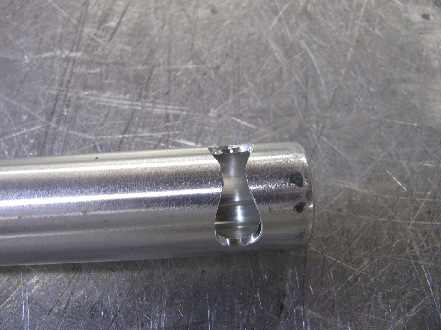
Fellow Vanagon mailing list member Stuart M asked me to make some sockets to affix to the westy rear seat so that the stock plastic insets could be fitted and then spread rests installed. I think there was a factory part made to do this, and I believe it involved cutting out a little of the plywood in the seat back. Also , some folk made steel tube versions of what I did. I believe ther is a Samba thread on that, yes there is, it’s here. As I work mostly with aluminum, I made a couple of pairs out that wonderful metal 🙂
I don’t know if you can make it out, but the slots on the top of the tube are of different width. That’s because the plastic socket has two rails down each side and the rails are different width. And i suppose its obvious that with this hack you have to sand off most of the plastic rails leaving just a little bit to engage the slots.


Vanagon – rear jack point/trailing arm protector
Posted by albell in vanagon mods on March 24, 2015
I’ve had a copy of the VW publication “Journeys under difficult conditions” since the early nineties. It’s a guide to modifications and tips for vanagon and LT owners who are planning on taking some rough trips. You get the impression that it is mostly centred on trips to North Africa, but the body protection modifications are pretty universal.
I only have a photocopy of the document, but I think it has been uploaded elsewhere. Maybe syncro.org.
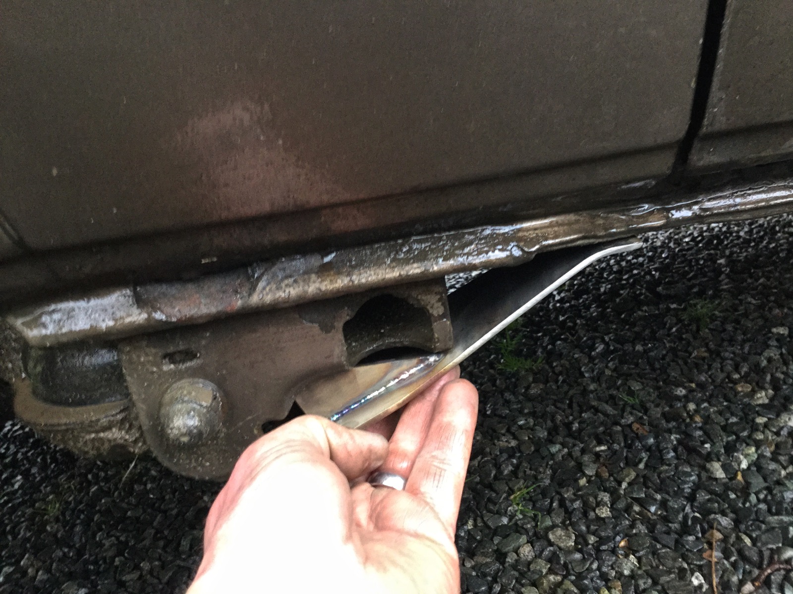
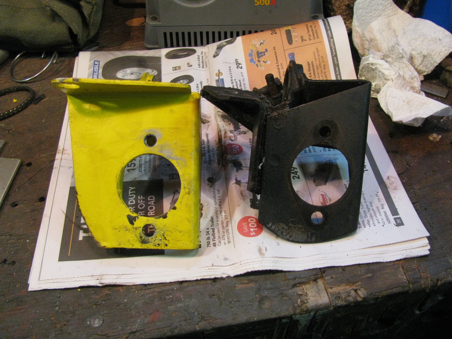
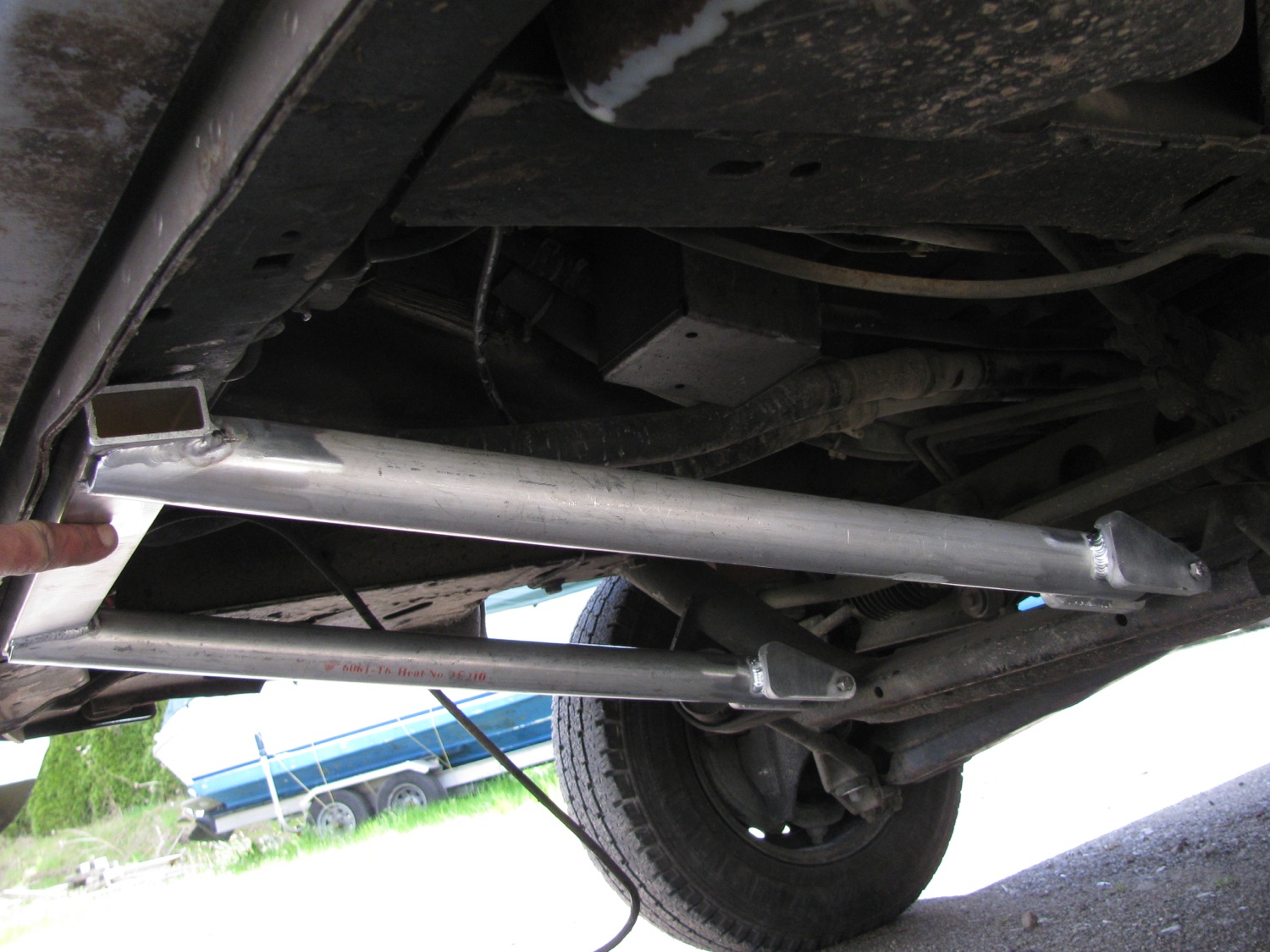
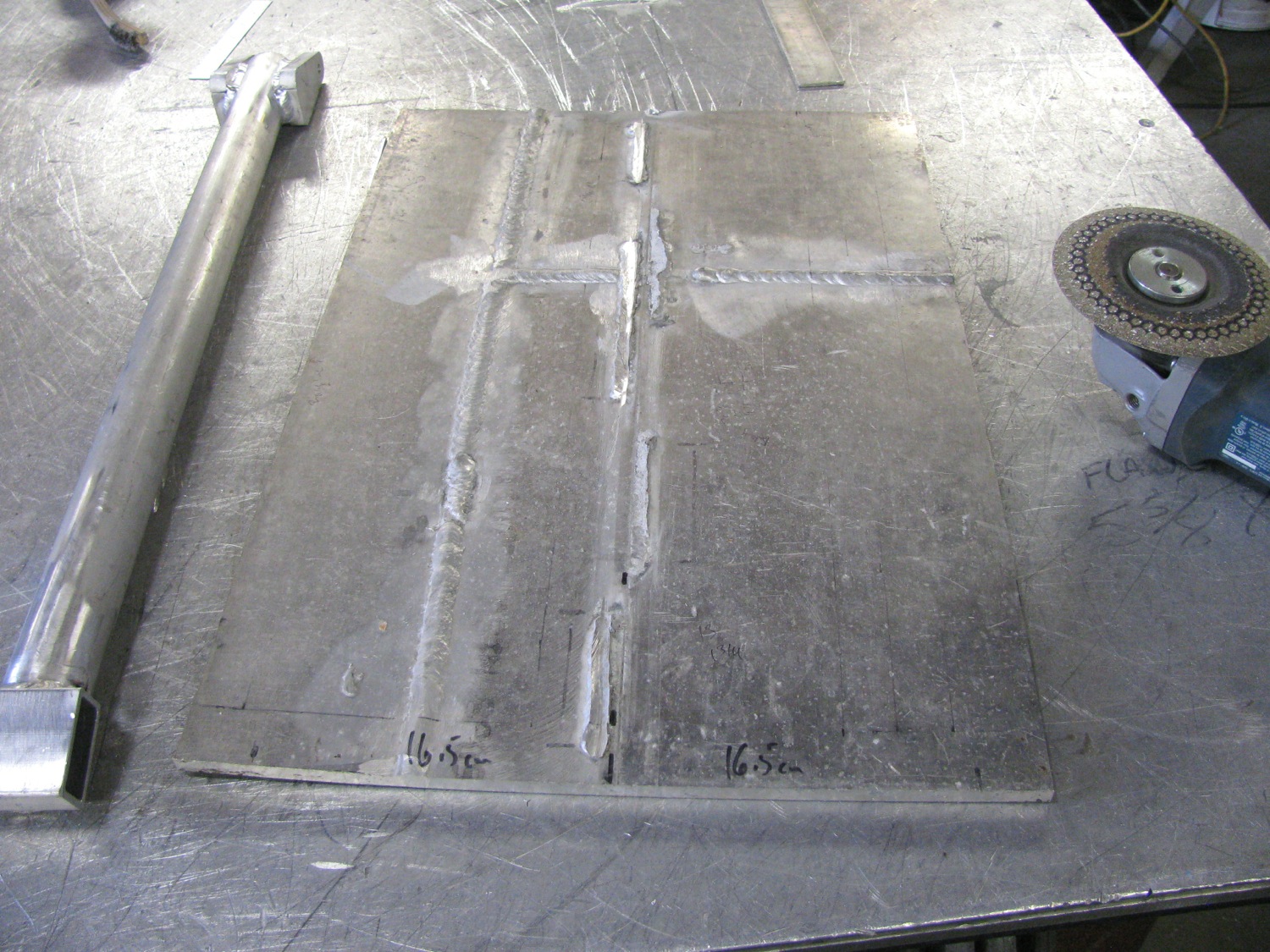
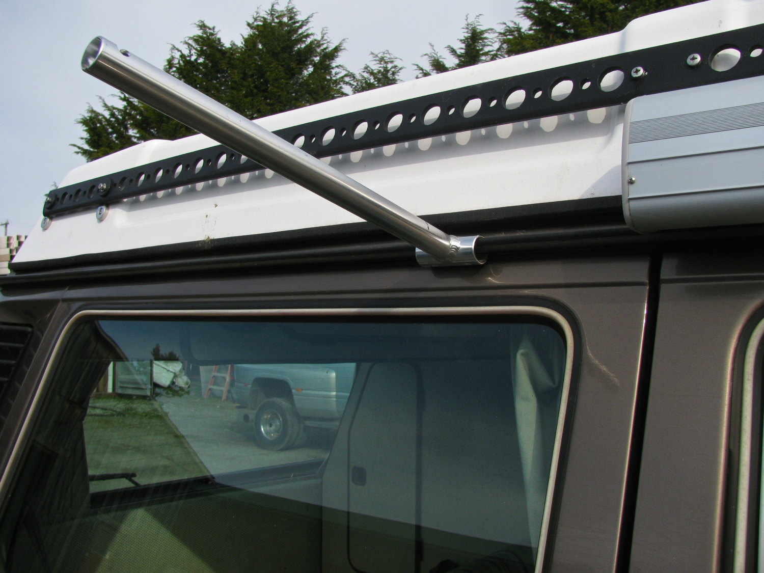
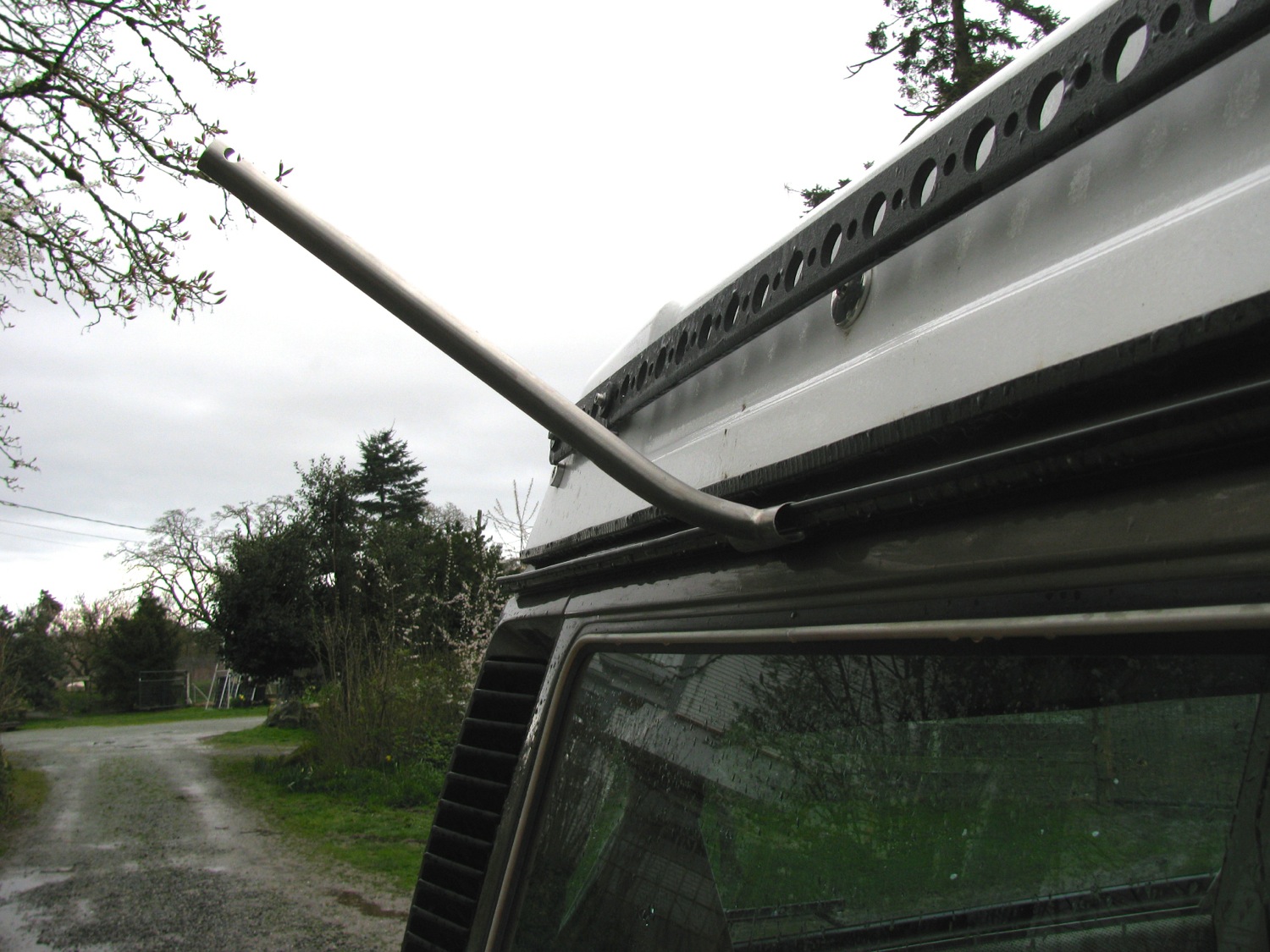
Anyway, I finally made something from the plans. It’s a simple little thing meant to protect the rear jack points and trialling arm outer mount from damage. I made it from 316 stainless and just cut the stock with an angle grinder and zip disk. I made the bend in a vise, you can see the bend is not as crisp as it would be if i had used a press brake. But it fits up fine.


Vanagon – quick peek at my front bumper build
Posted by albell in vanagon mods on March 24, 2015
i still haven’t completed my rear bumper, I have it installed but unpainted and struggling with a good latch for the swing away tire carrier. I’ve tried a few ideas, but not happy with any of them.
But that hasn’t stopped me from starting a front bumper. Here is a picture when I was deciding on hole placement for auxiliary light mount. Btw, made from 1/4″ 6061 aluminum, that flat section in the middle is 3/4″ thick. As much as it looks like it, the flat section is not for a European style license plate but rather to mate with a replacement for the stock tire carrier – the forward end of the carrier will curve up in front of the bumper. Link to that carrier here.

Interesting little film trailer
yeah, I’ve got good reason to post this here 🙂
Sorry for the dearth of postings
apologies for the silence over the last few months, I’m getting back on it. I have a few vanagon modification postings in the chamber, will be posting them in the next couple of days.
i also have to catch up on comments.
Vanagon – behind the rear seat sliding cover
For educational purposes…pdf file
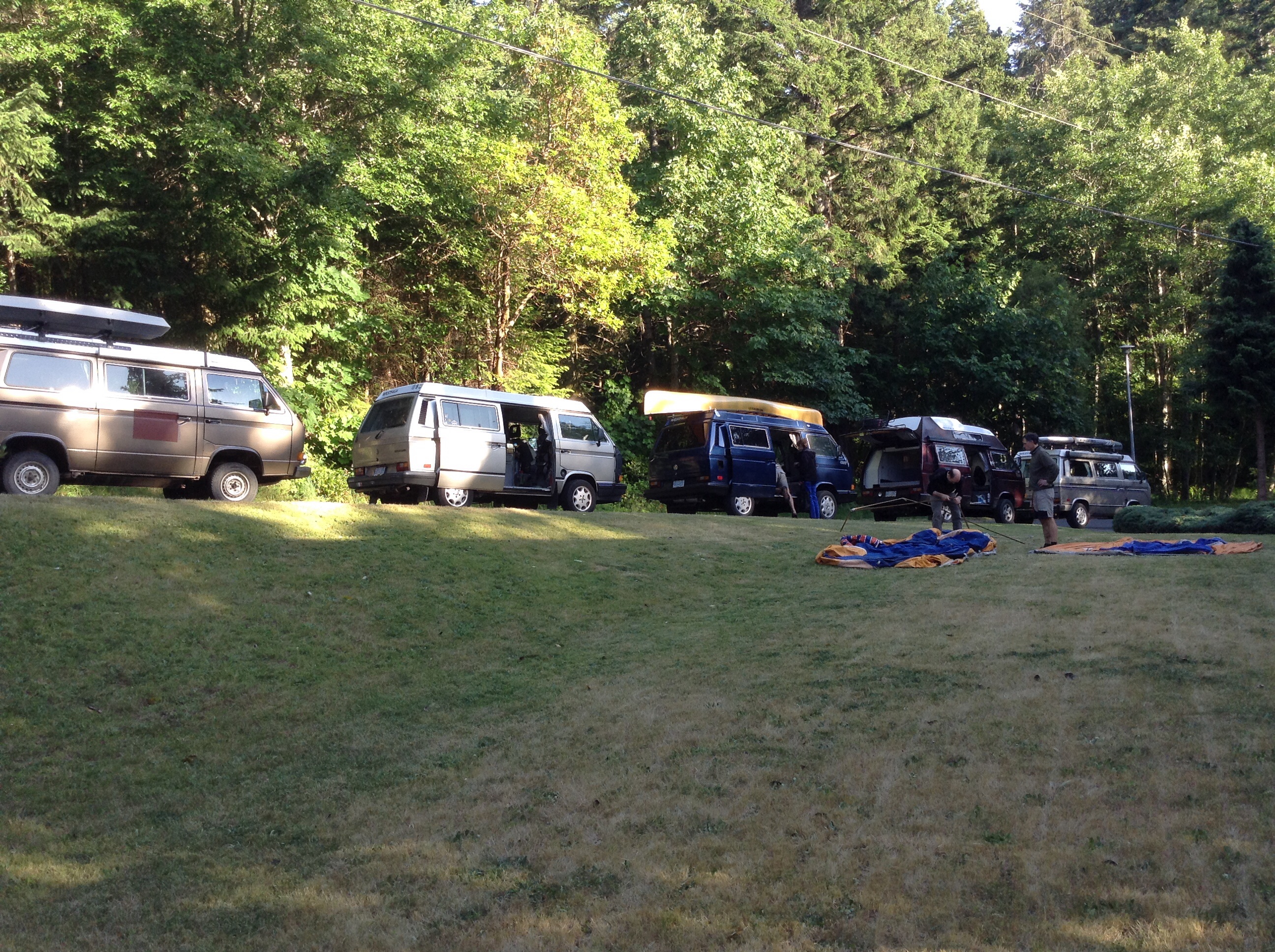
Vanagon – line of vans
Dinner party at a friend’s house this summer.

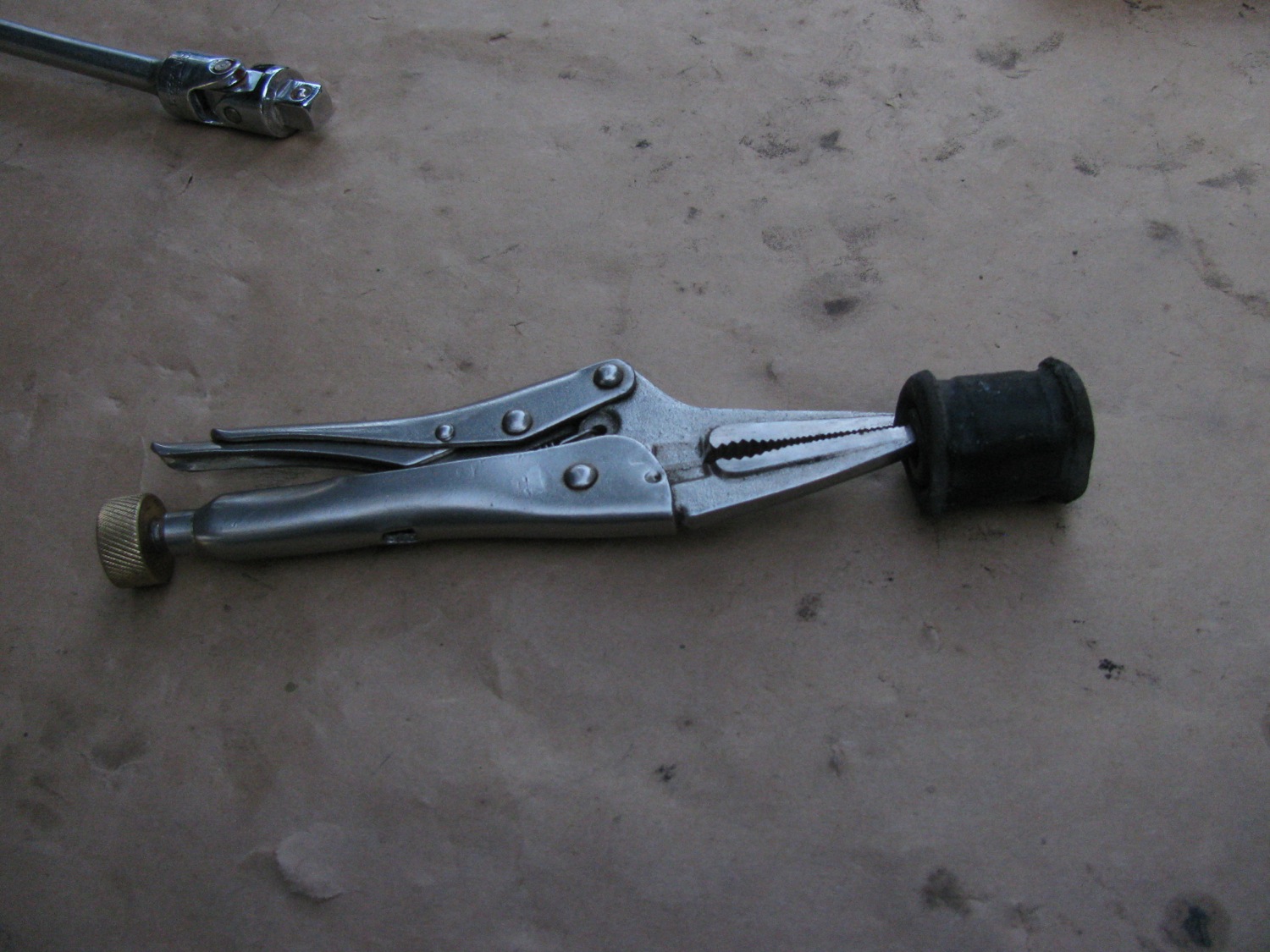
Vanagon – quick throttle body re-bush
Posted by albell in vanagon, vanagon mods on September 13, 2014
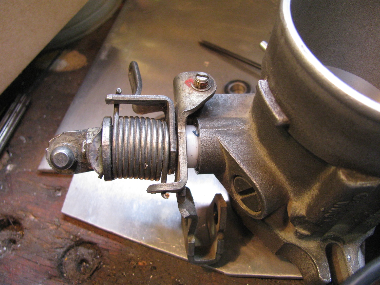
A few years ago i tried re-bushing a spare throttle body using Delrin as the bushing material. I couldn’t get the throttle action smooth, it seemed as if the Delrin had a stiction property that I just couldn’t over come either by sizing the bushing or lubricating. So I laid the project aside and forgot about it.
Then this last summer I noticed some play in the shaft of the throttle body installed in the van. There was enough play to make adjustment of the throttle position switch very fussy. So i though back on my previous experiment and I thought I’d try making bushings again, but this time out of HDPE.
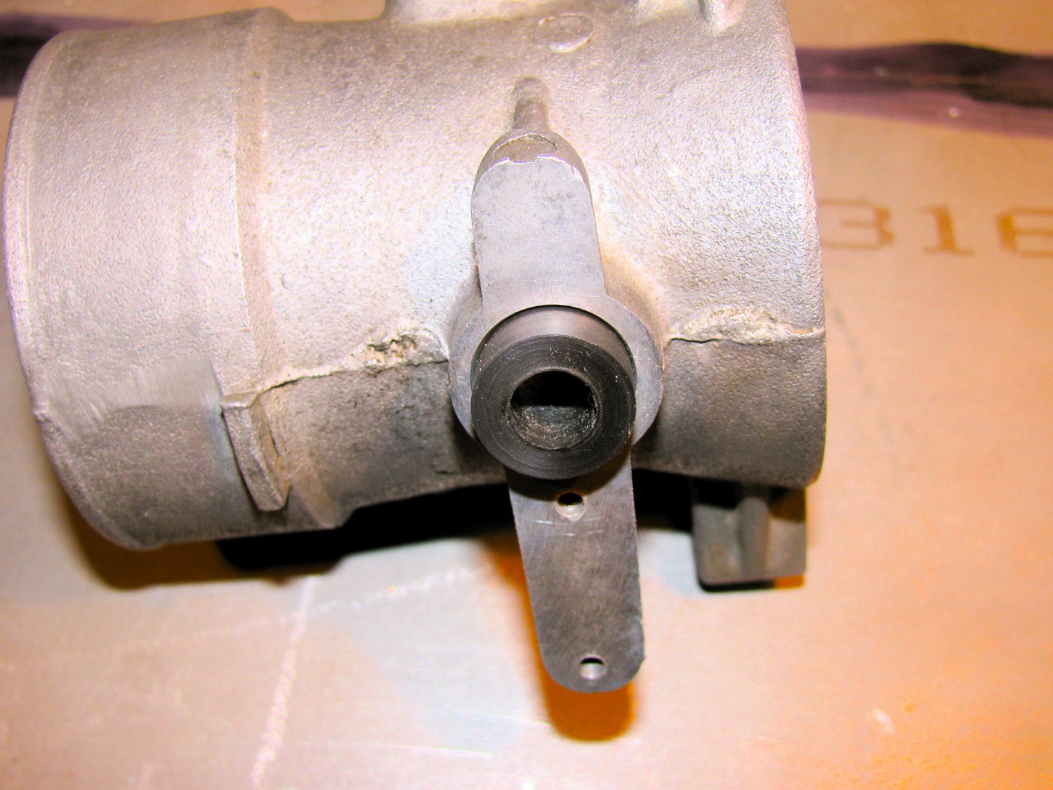
First let’s go back to my spare throttle body, the one I re-bushed with Delrin. I have a blog post here showing it before I started screwing around. I even went as far as cleaning up the wear marks in the bore and making a new butterfly plate to compensate for the now enlarged bore.


See the Delrin bushing?

And on the other side, the throttle position switch side.
My daily driver one on the left, the re-furbed one on the right.

Not the larger cam on the one on the left. This is the newer, revised throttle position switch system.

It appears like a lot of space around the butterfly, but it really isn’t that bad. I can’t recall the gap size (I measure with wire).

It kinda looked ok to me.

The dried up seal on one side.

And the other.

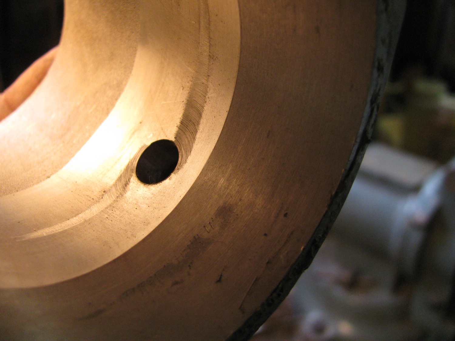
Wear in the bore from the butterfly.

I decided to leave bore and the butterfly untouched. I chucked up a hunk of polyE and turned and reamed a couple of bushings.

Recessed on the throttle position switch side.Why? because the switch plate has little locating tabs that fit into the hole.


Pretty well flush on the other side.

Gosh, i can’t recall for sure the butterfly shaft diameter, maybe it was 8 mm, yeah I think so. I do have an 8mm reamer. Anyhow, I did think about bearings instead of bushings. But the bearings I had on hand had a larger OD and that would have meant taking the throttle body to work to use the milling machine; tedious set up and then a boring head.

Assembled. I have to say the action of the butterfly is smooth as silk, much better than the Delrin. Come to think about, I wonder if I reamed the bushings the last time?
The throttle position switch now is easier to set, there is no wobble in the butterfly shaft.
Trips – a couple from August
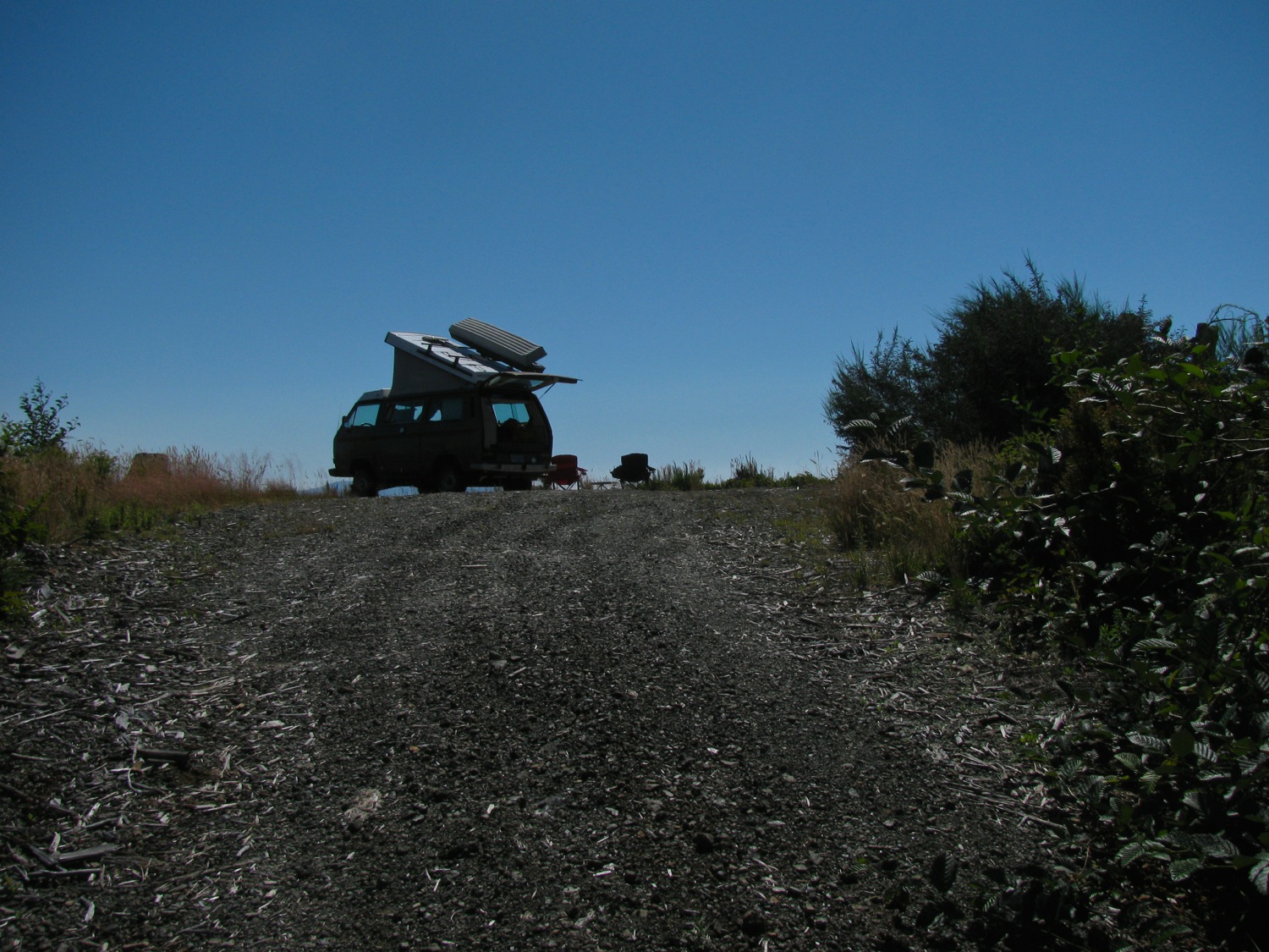
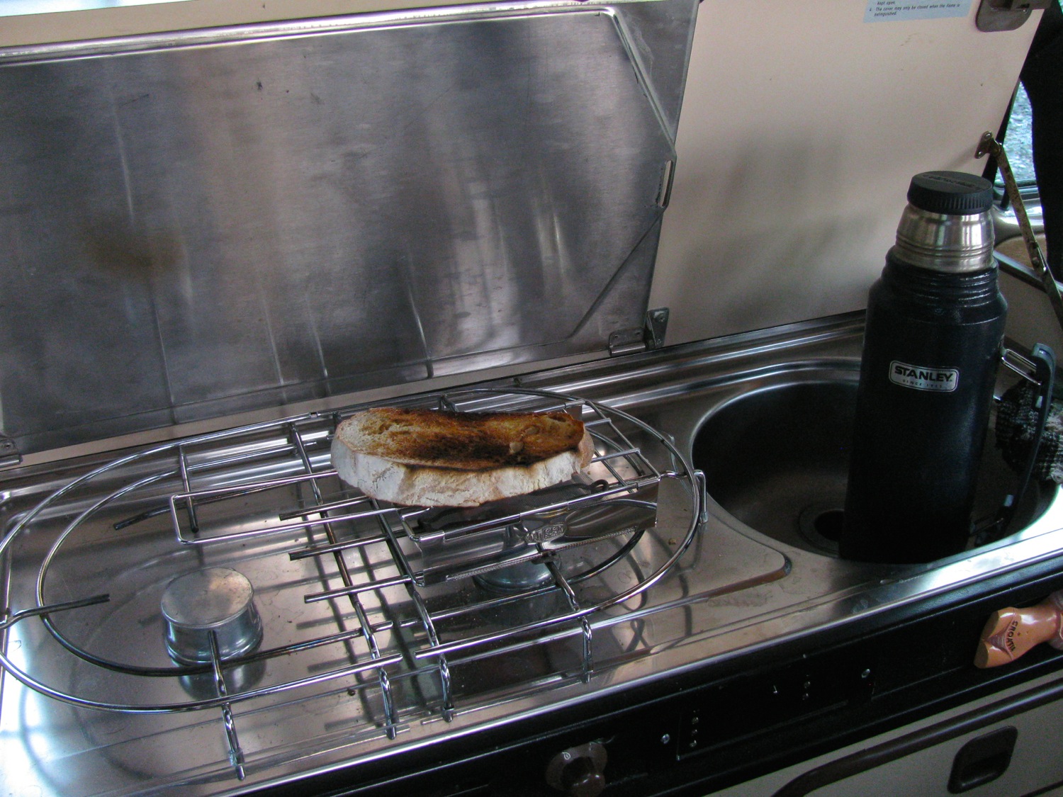
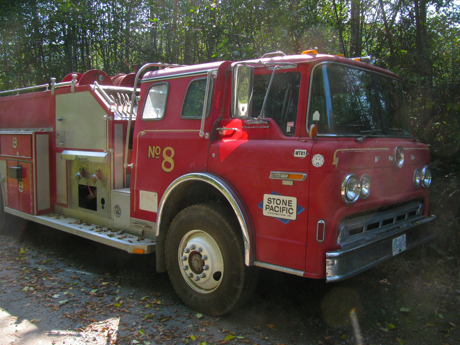
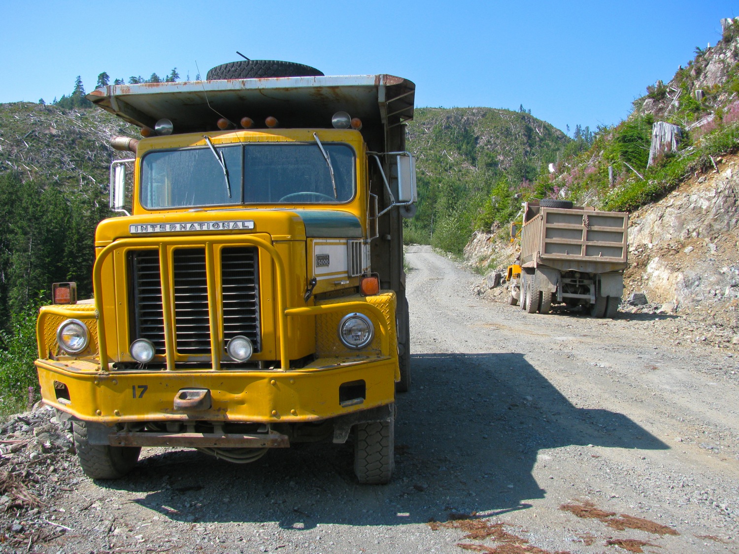
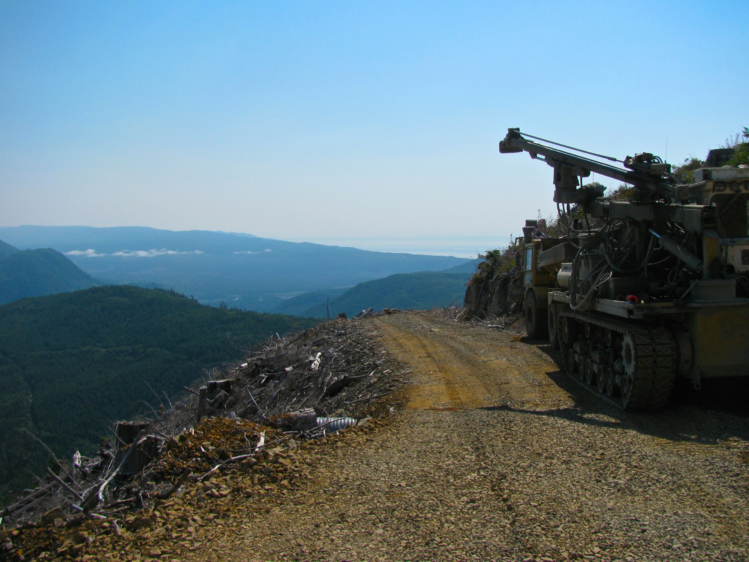
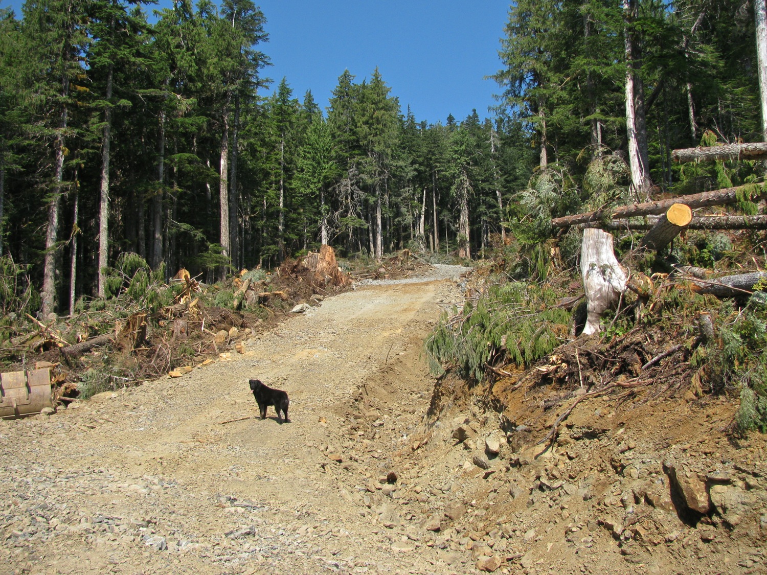
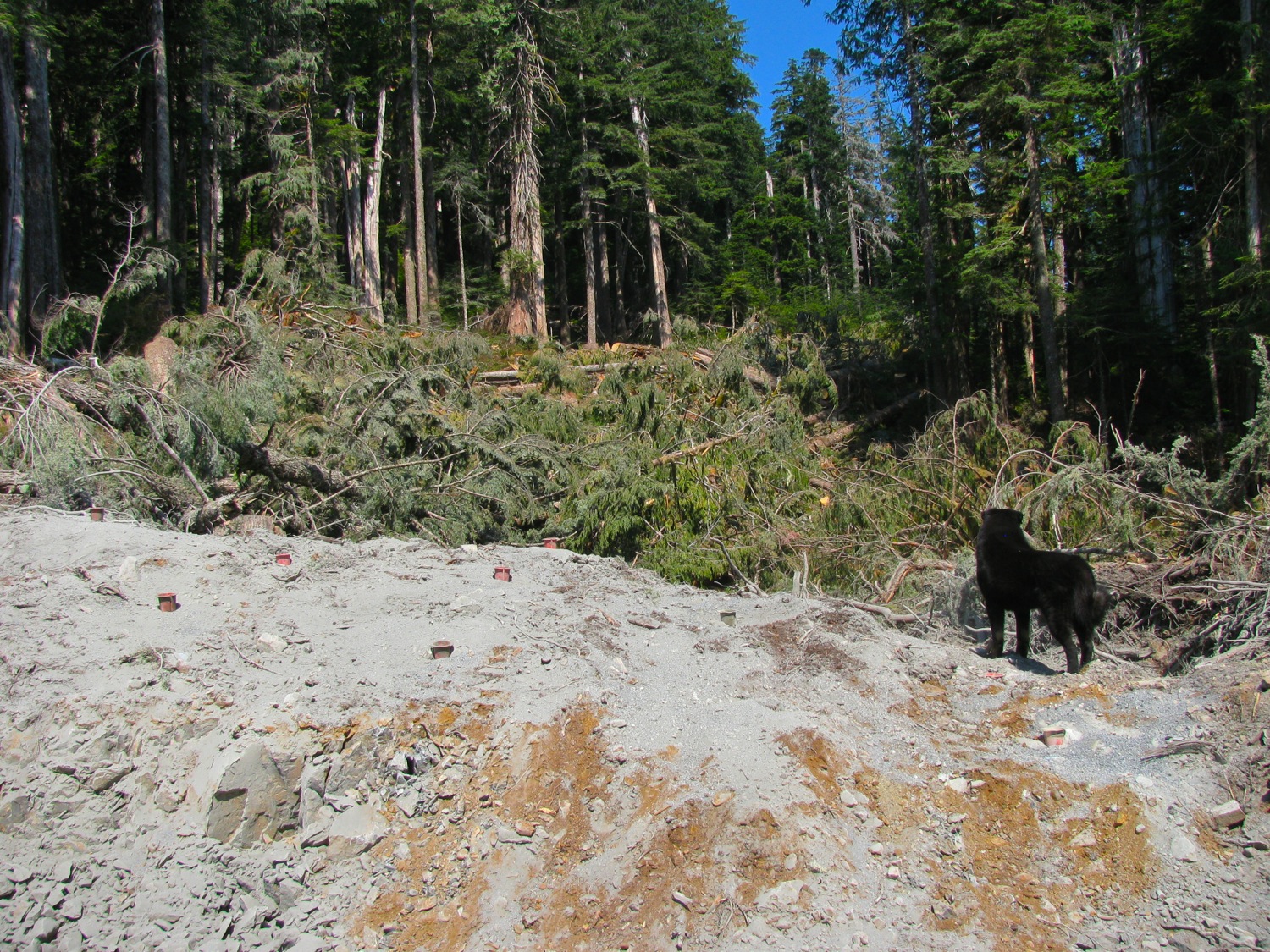
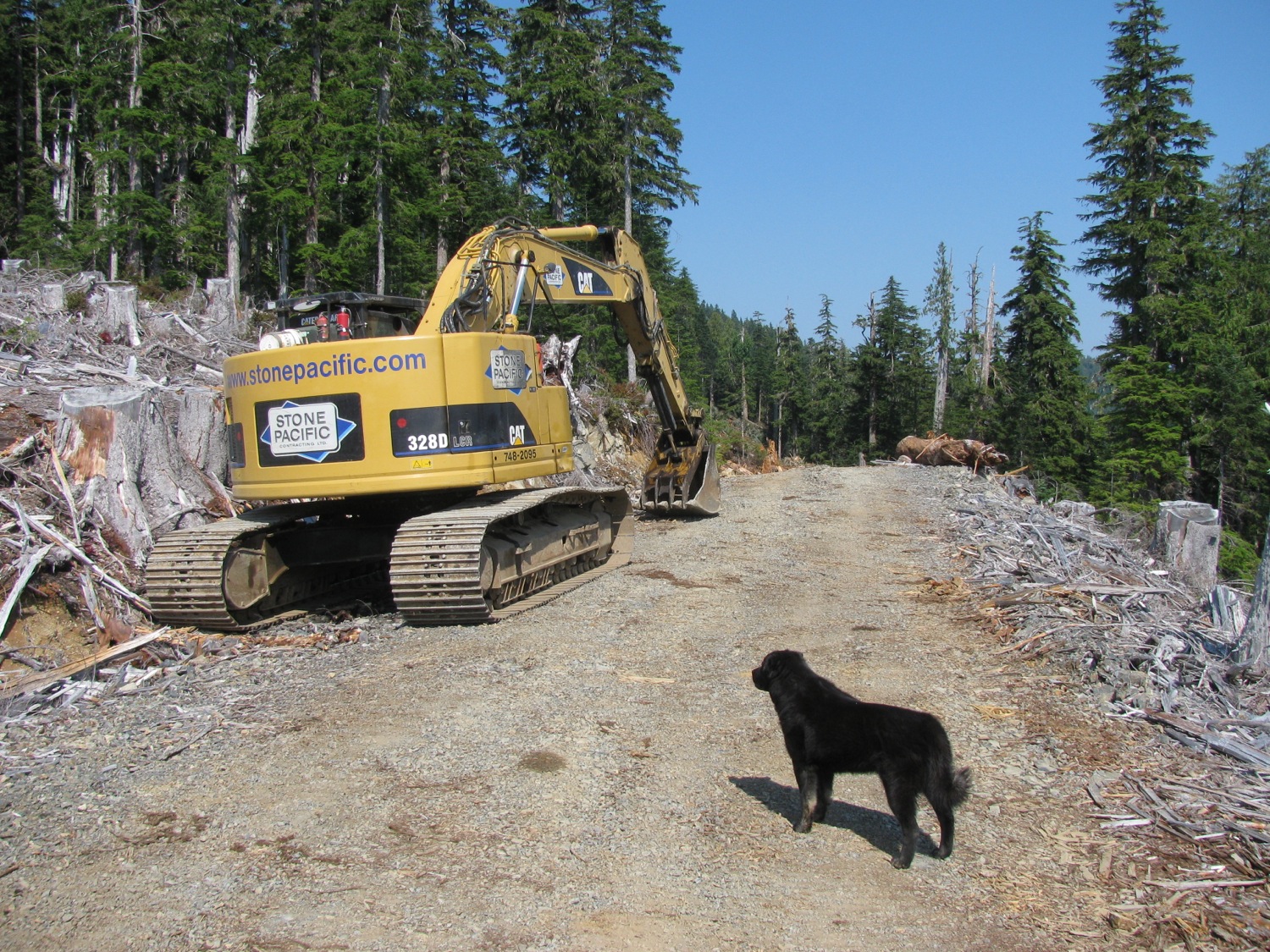
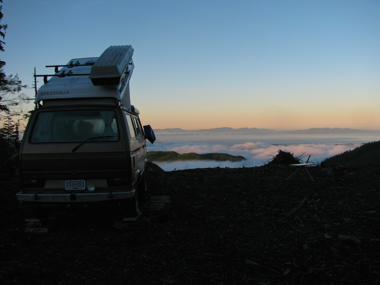
Instead of boring you with text I’ll just post some pics from a couple of trips made in August. The road building is at about 750m elevation, mostly Yellow Cedar, some Red Cedar (that rotten stump was about 10′ across, some fir and a little spruce. Logging road building now seems to use just a drilling rig, some sort of dump truck, and an excavator. No cat involved. Arrow pointing to the hoosegow above Clallam Bay Washington. Deck cloud makes it look like it is lower on the hills than it actually is. 

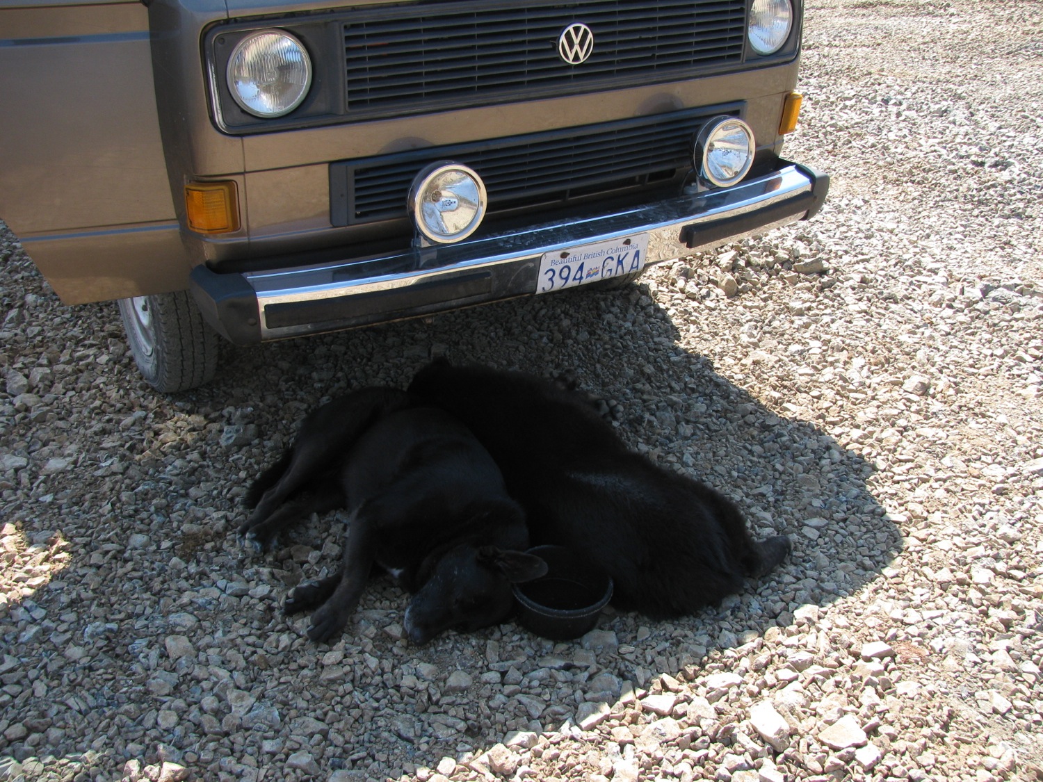
 What’s this, a new toaster? I couldn’t resist, here is MEC link. It works quite well.

 You can just make out the beach at Port Renfrew in this pic.


ok, got some vid clips, left over from personal stuff, of these two trips. Really not very well done or exciting but I thought I throw them up here. The fast motion part was trying out a not very successful dash mount for the GoPro.
Vanagon – front suspension bushing work
Posted by albell in syncro specific repairs, vanagon, vanagon mods on September 12, 2014
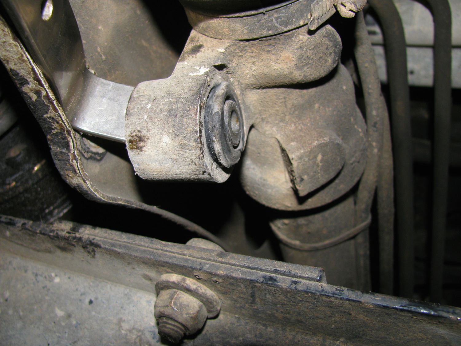
About a month ago i replaced a few bushings on the front suspension of my ’86 syncro. They were they sway bar to body bushings, the sway bar drop link to control arm bushings, and the steering rack bushings. I replaced them with Whiteline polyurethane bushing from Chris at T3 Technique. I can whole heartedly endorse Chris for his great customer service and products.
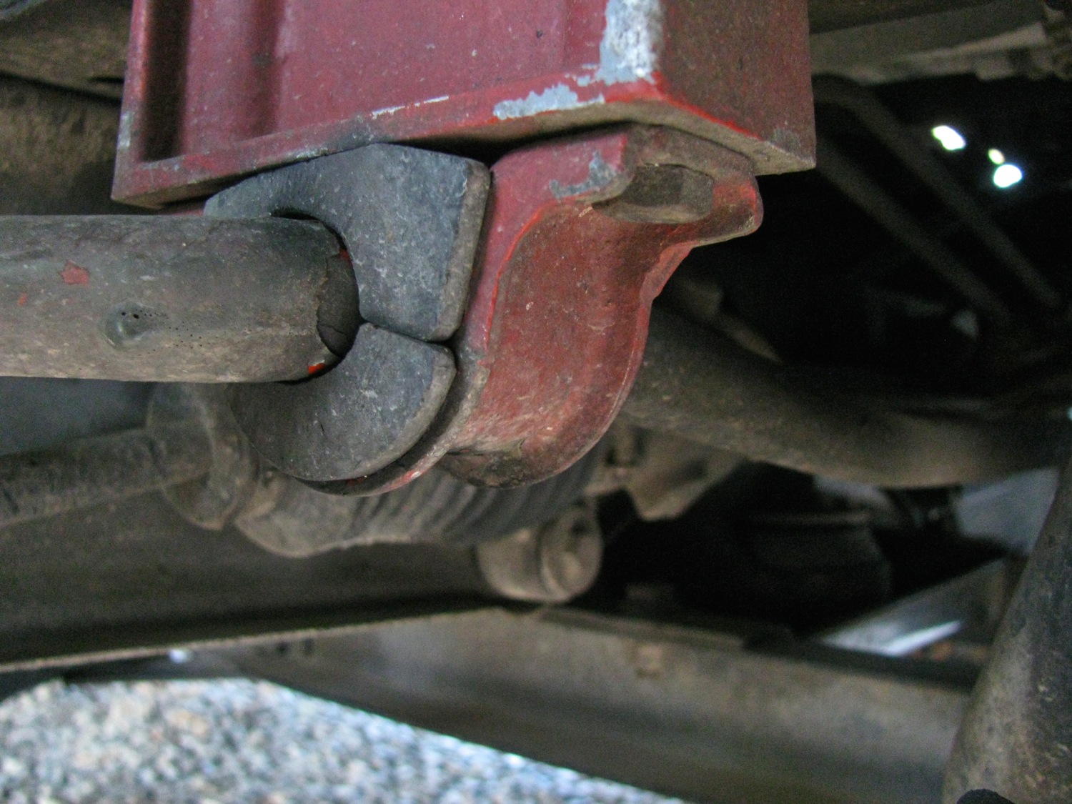
So first the easiest, the sway bar to body mount bushings. Here is a pic of the one of the original rubber bushings.
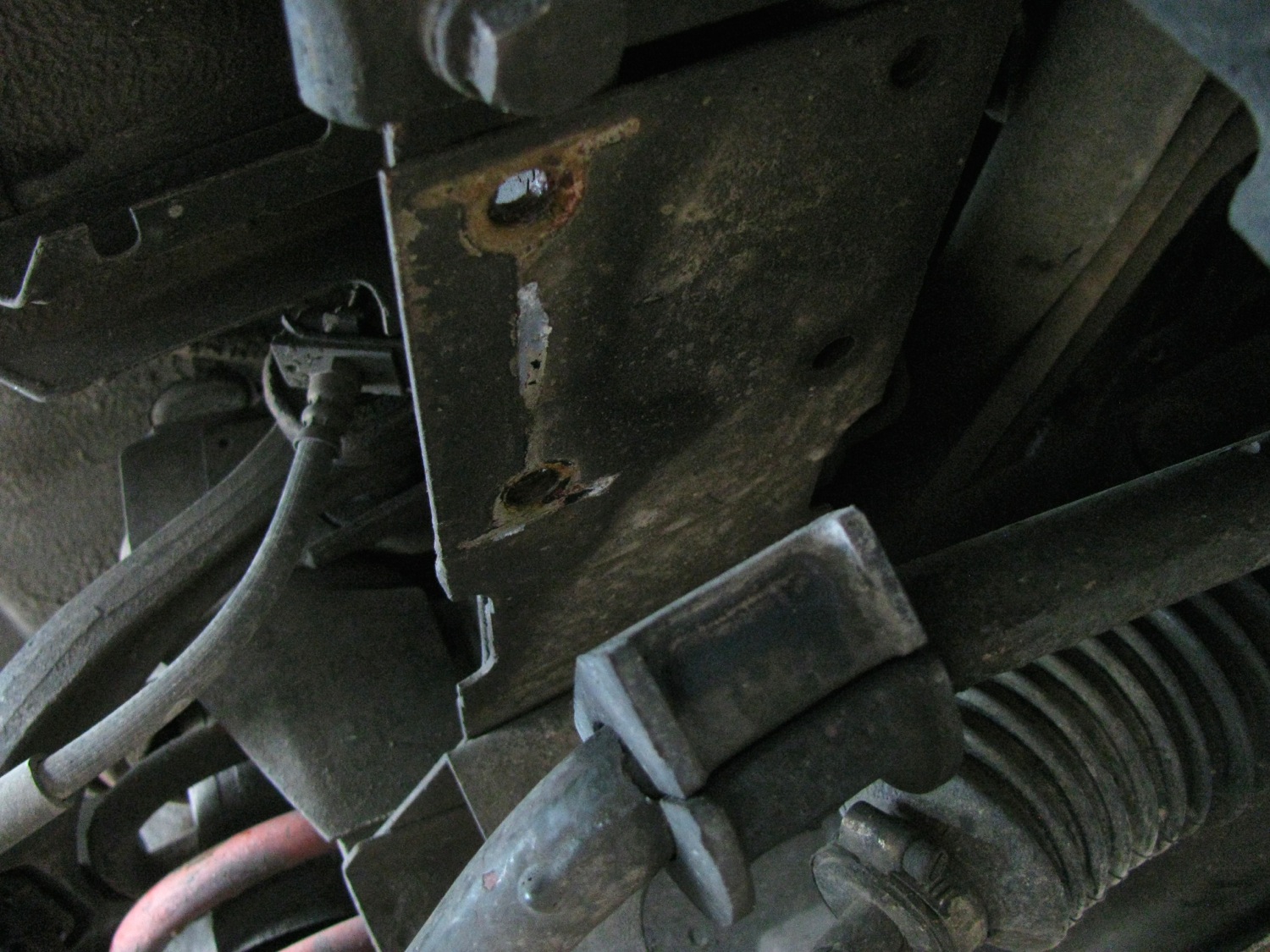
A couple of 13 mm head nuts and bolts and the mounting bracket comes off. Note the spacer used in the syncro bracket.
New bushing comes in pairs, and with a sachet of grease. Grease is important in polyU bushings. They do have a reputation that they squeak, so you must grease them up with s low wash out grease. T3 techniques sells a couple of greases, and I bought one of them, Accrolube. I didn’t know when i ordered that the Whiteline bushing come with their own grease. So you might see in the pics that i have used both the black grease from Whiteline, and the blue Accrolube. Note that the Whiteline package has instructions on where to apply the grease, important for bushings that undergo twisting motions.

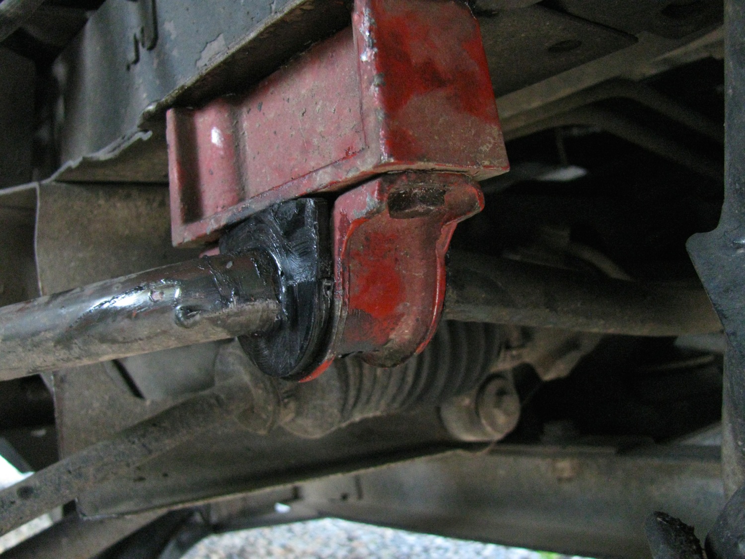
Pretty easy install.
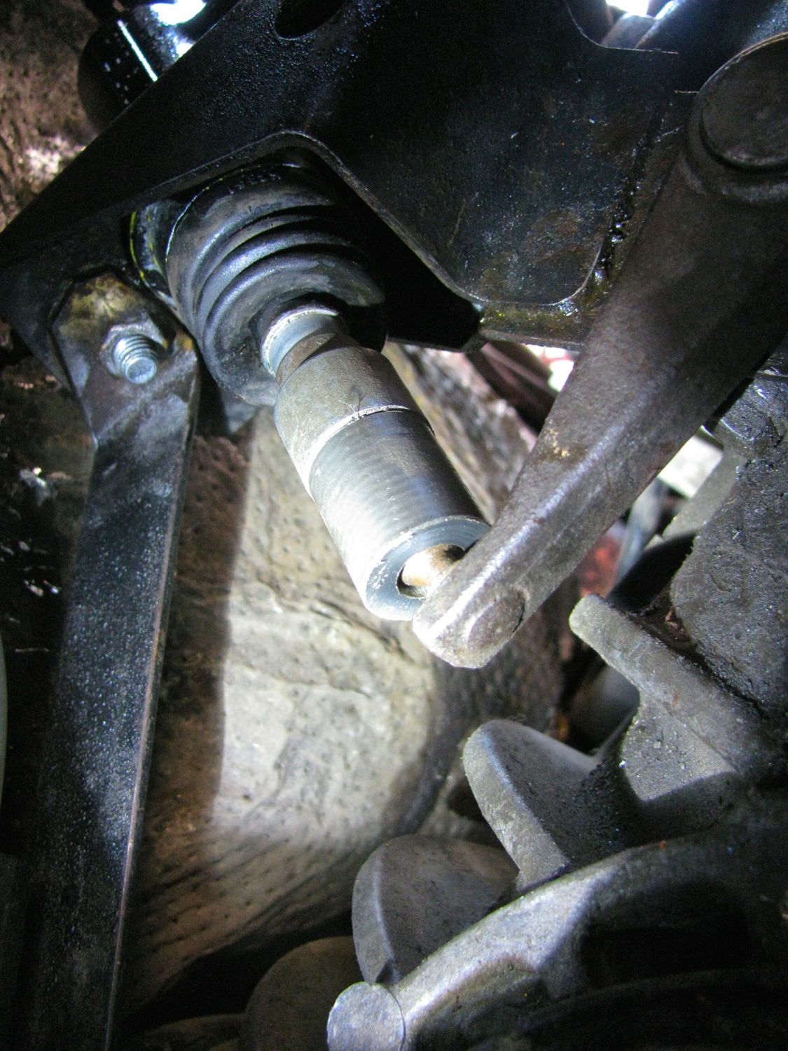
Next up are the drop link end bushings. You can read all about what I had done to the drop links a few years ago here and here
So far all the work has been done with van on the ground, but after I removed the nut at the end of the drop link I jacked the van up so that the drop link pulled up and out of the lower control arm. Be careful or course, block the van, support it etc etc. the drop link will come up out of the hole and then you can pull the sleeve and the topside bushing off. Look at that old bushing, that old home made bushing 🙂

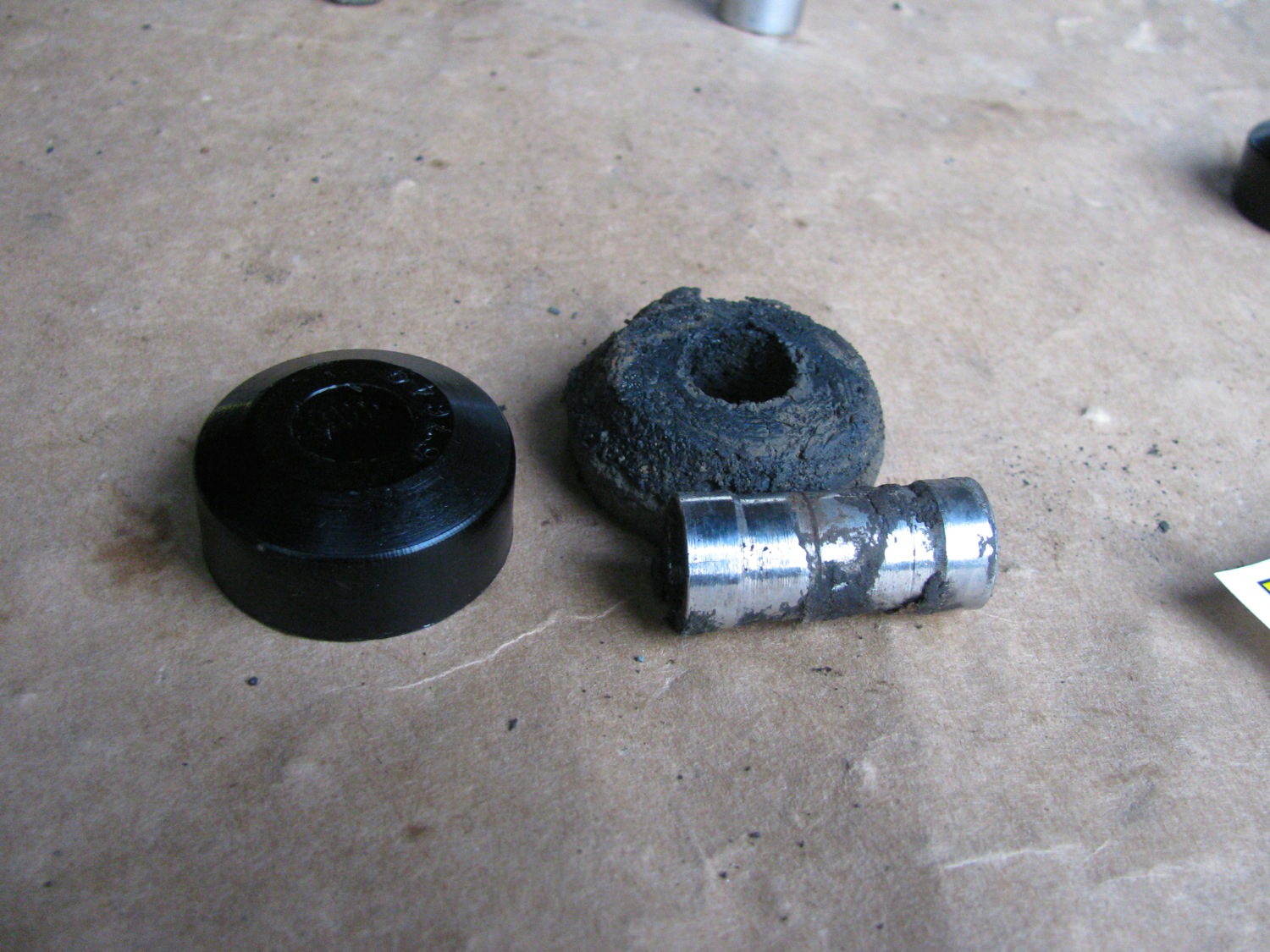
The homemade sleeve is holding up fine. Interesting grease residue marks in the middle, showing the edges of the bushings? also note the shape of the new bushing. It is flat one one side, domed on the other. The domed side goes into the control arm recess, the flat side faces the dished washer. The flat side really should be slightly domed or at least bevelled, I think. Chris agrees. I modified the bushings on the other side, ground a bevel on them, but of course didn’t take a pic. I think the bevel roughly matching the curve of the dished washer would allow a little more articulation in the joint.
Now the install of the new bushings. Dished washer on the drop link first, convex side facing bushing, then a bushing with sleeve installed in it and the drop link inserted in the control arm. van lowered off the blocks so the drop link is pushed in the control arm. but the new bushing is tight and not much of the other end sticks out. So even with van fully lowered, wheel on the ground, not enough drop link is exposed to get the other bushing installed.

So i rigged up a ratchet strap and pulled the drop link down. Also disconnected the sway bar to body bracket. Even then it was a bear to get the lower bushing installed.
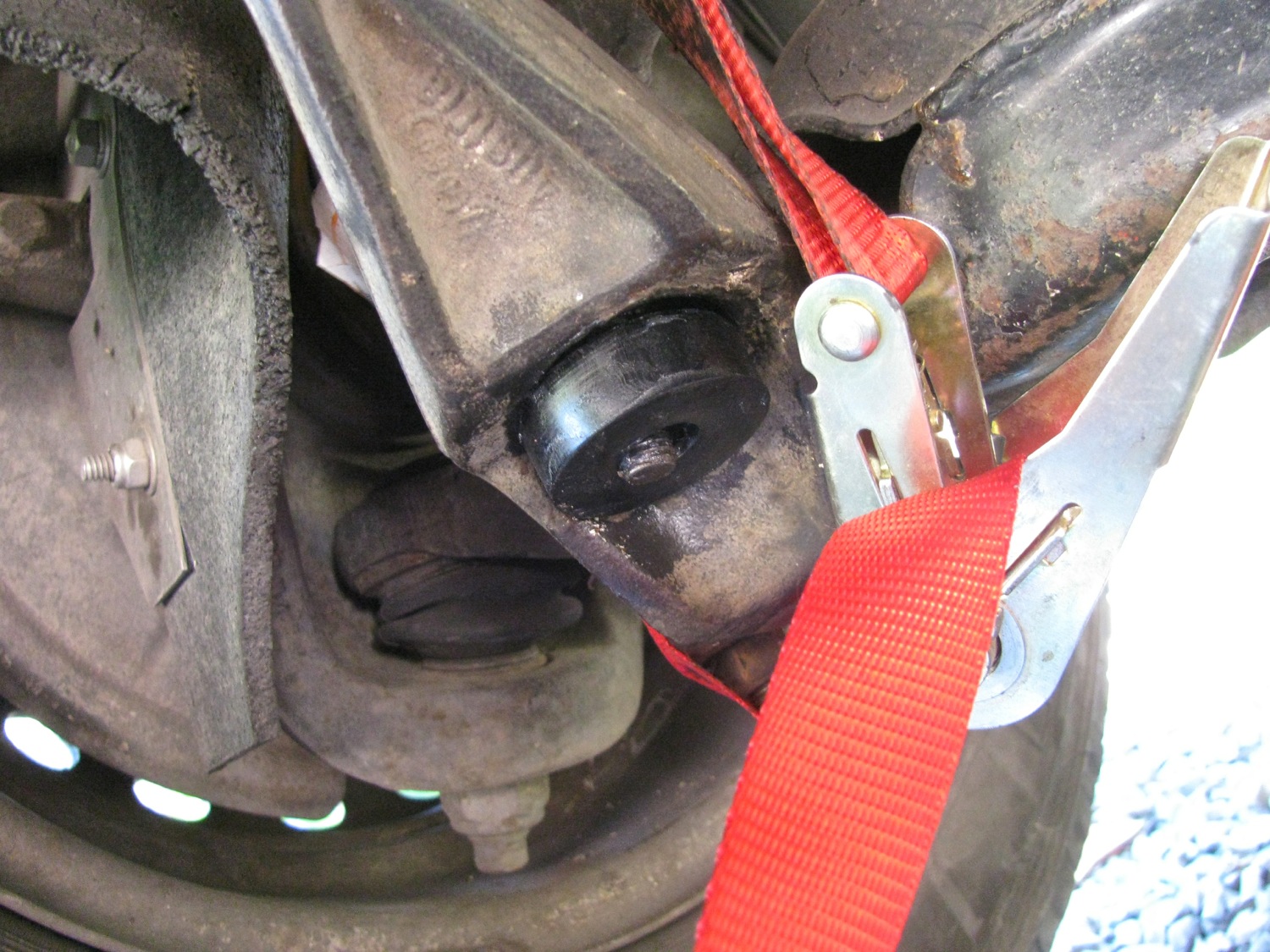
I certainly couldn’t get my dished washer installed so I pulled the bushing in as tight i could with a plain flat washer and the nut. I would do the nut up tight then remove it, put on the dished washer and try the nut…. just wouldn’t catch the threads. My home made stainless washer was too thick.
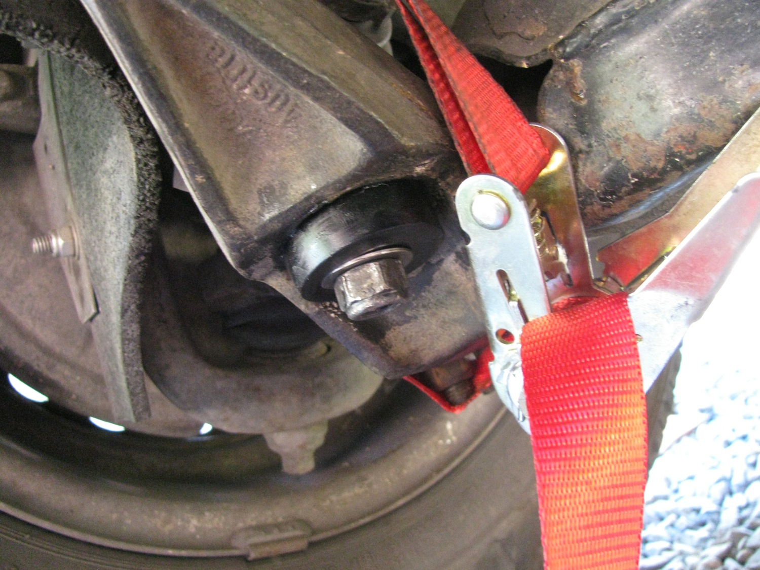
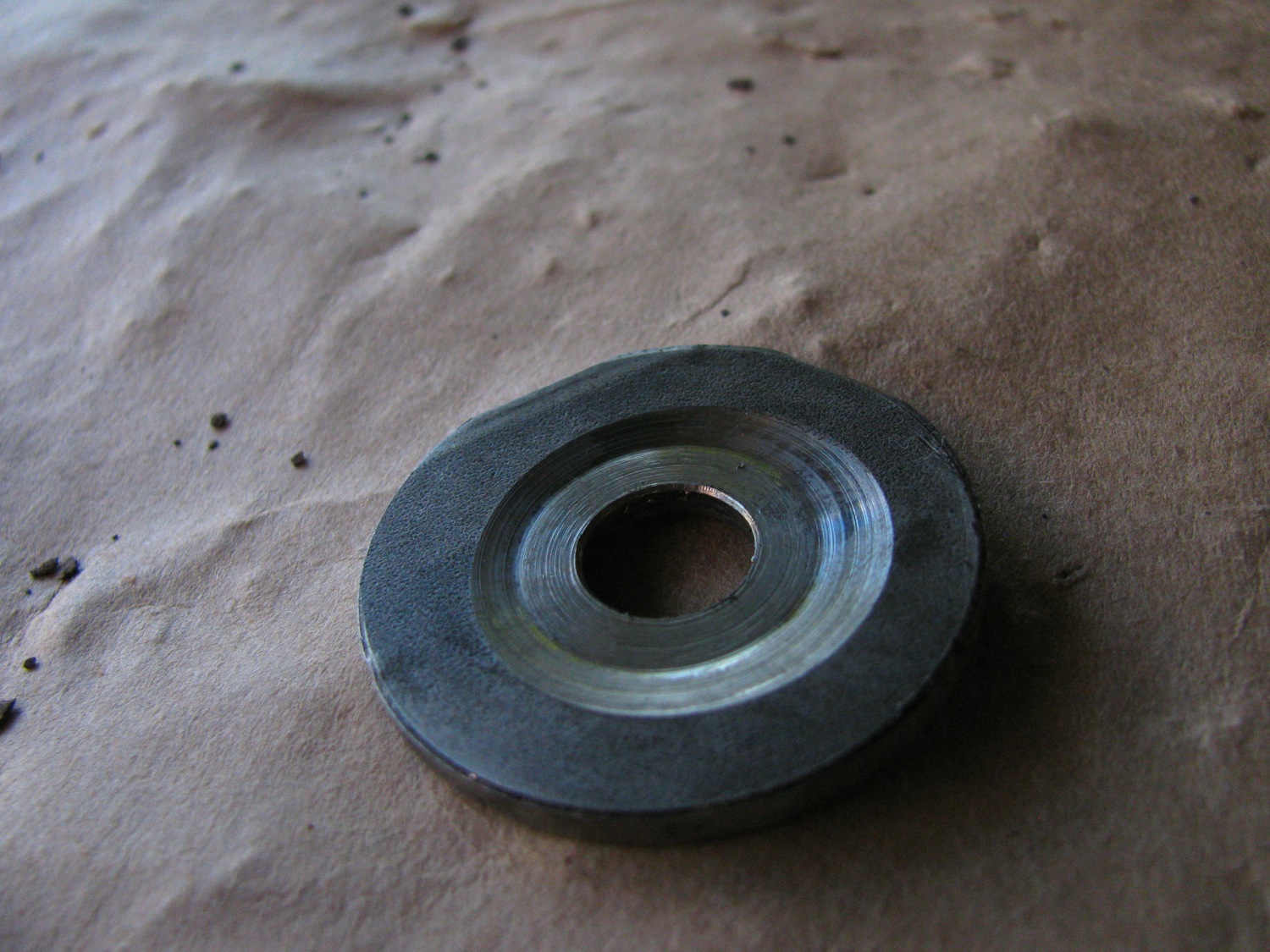
So i turned a recess in the washer and after a bit of a struggle and a lot of cursing, i got the washer and nut on. The other side was a tad easier with the modified bushing. But this part of the job took me a couple of hours.
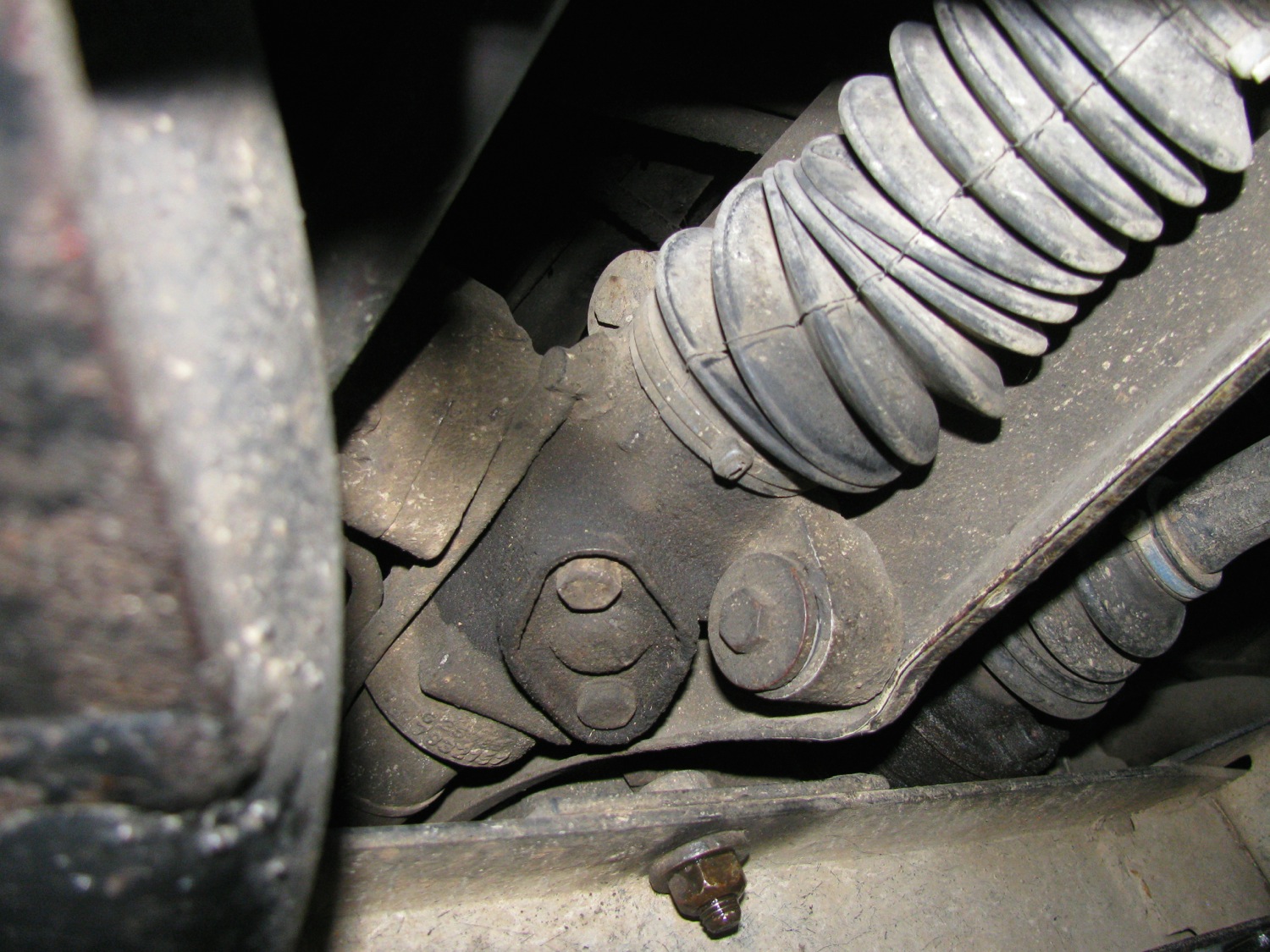
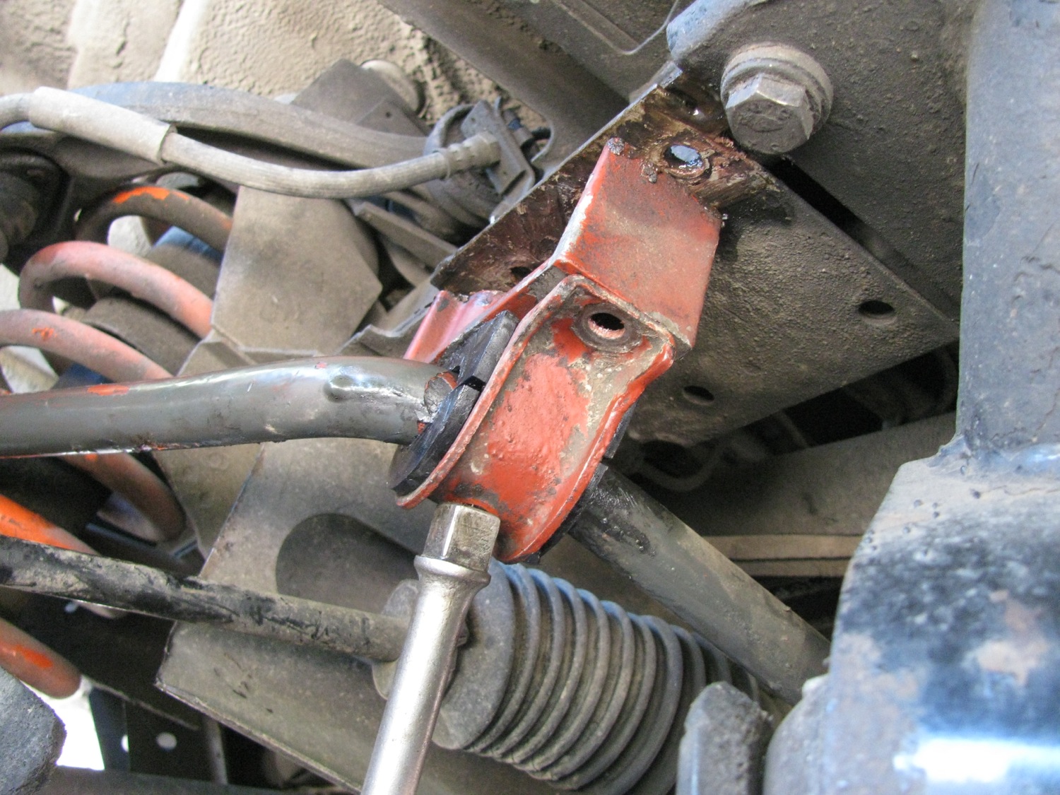
Now on to the steering rack bushings. There are four of them, upper and lower, left and right. Here you can see the lower on the right hand side. The bolt goes throughout the bushing and frame member and there is a stover type nut on the end. I would advise you to soak the nut side with penetrating oil a couple of days before you do this job, there is a fair bit of exposed thread on the bolt and they can be rusty.
I started by loosening all four bolts, but not all the way. Then had at the lower left side bushing. I removed that bolt, oh careful, there is s slim washer under the nut. The with a slim small pry bar i pushed the bushing out from behind. Remarkably it came out quite easily. On a couple i grabbed the bushing with needle nosed vice grips to ease its passage.

They seem to be in pretty good shape.

The new bushings are two piece with supplied sleeve.

Pretty easy to install. I did one at a time but didn’t tighten up until all installed.

Yeah, supervisor was checking in.
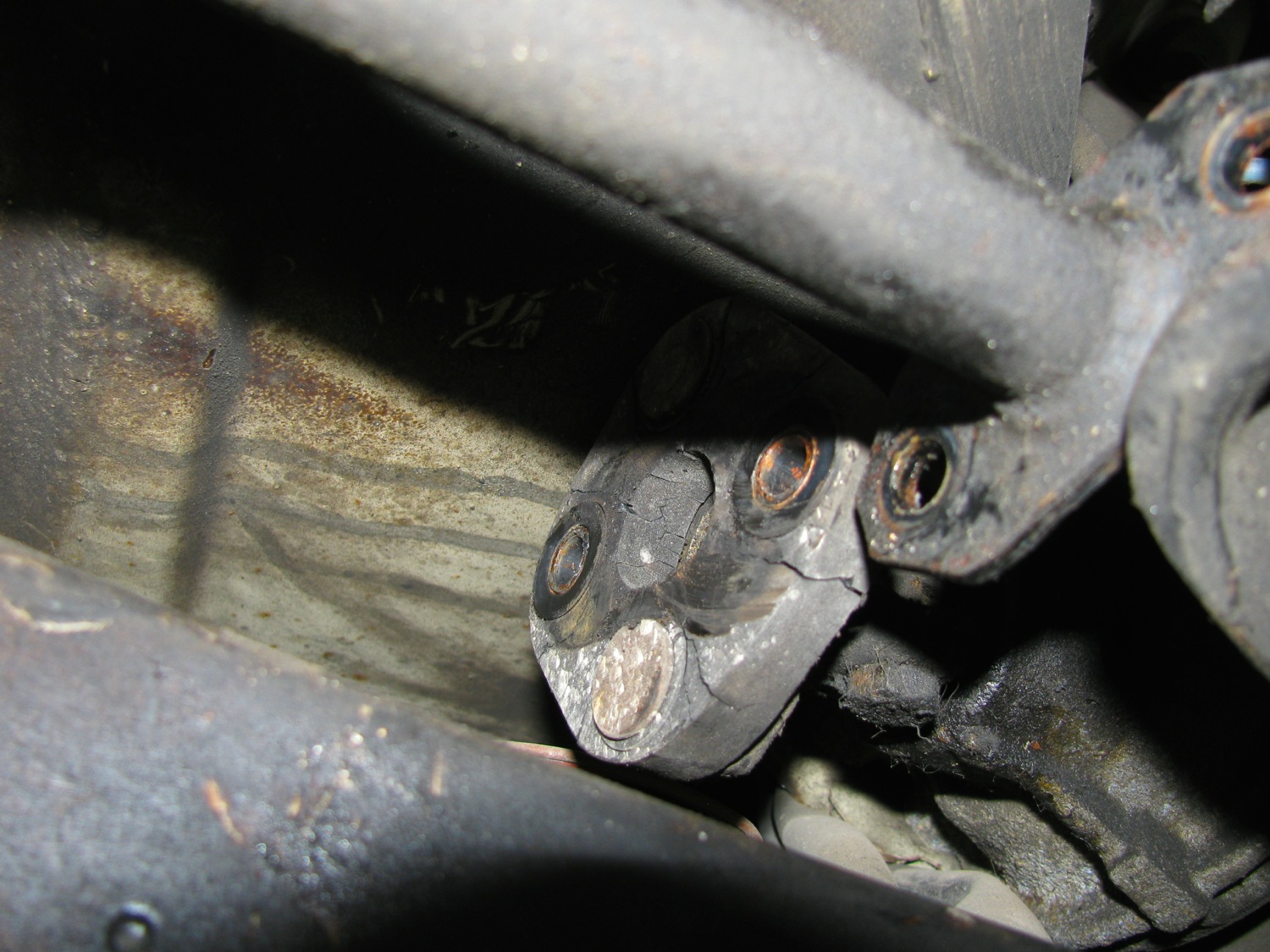
Now on the driver’s side the steering rod (from steering gear box to steering rack) prevents the steering rack from being pried forward enough to both pry out the old bushings and install the new bushings. I disconnected the coupling at the forward end of the rod and loosened the slimed coupling at the u-joint in the rod. It was only later, looking at the pics did I notice the cracks in the rubber coupling, sheesh, another thing to replace.

Wrench access on the driver’s side is a bit restricted, so it take a little longer. But these bushing took less time to install than the drop link bushings.
So the verdict? I could really notice the steering response improvement, especially at highway speeds. I’d recommend the rack bushings even if your existing bushings are in good shape.
Vanagon – body insulation idea
Posted by albell in vanagon, vanagon mods on September 11, 2014
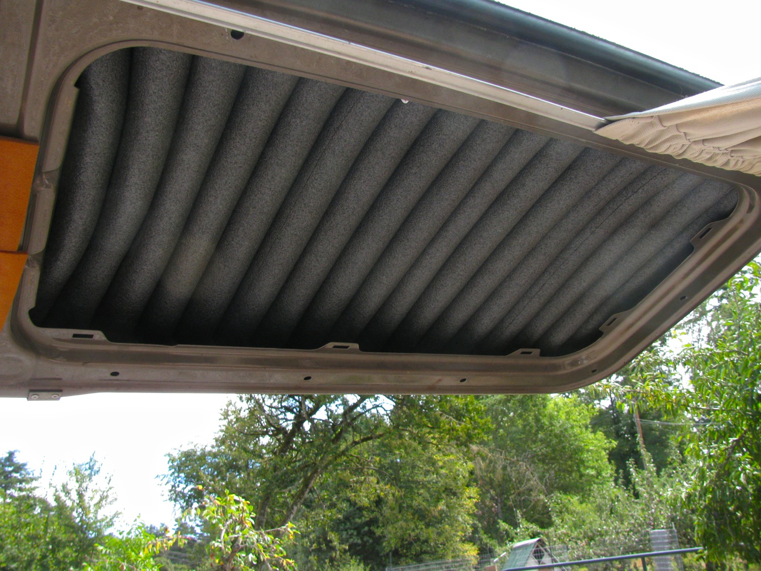
Saw this on the samba, i think it was syncroghia that posted in his thread about adding high top to his 16″ syncro. I thought it was a good idea so i gave it a go on the rear hatch.
It is just water pipe insulation, I think its foam polyethylene, cut to length and wedged into the cavity. Now that summer’s over one might find pool noodles going cheap and I think they would do too.
I like this because it is cheap and fast to install. No gluing and I don’t think it will trap moisture against the metal.
I stuck on a bit of peel and stick roofing stuff to dampen panel noise. My van had some factory applied bits already there. Remember this is a converted 7 passenger tin top. I don’t think we sties have the factory sound proofing in the back hatch, but they do have the dreaded fiberglass batting.
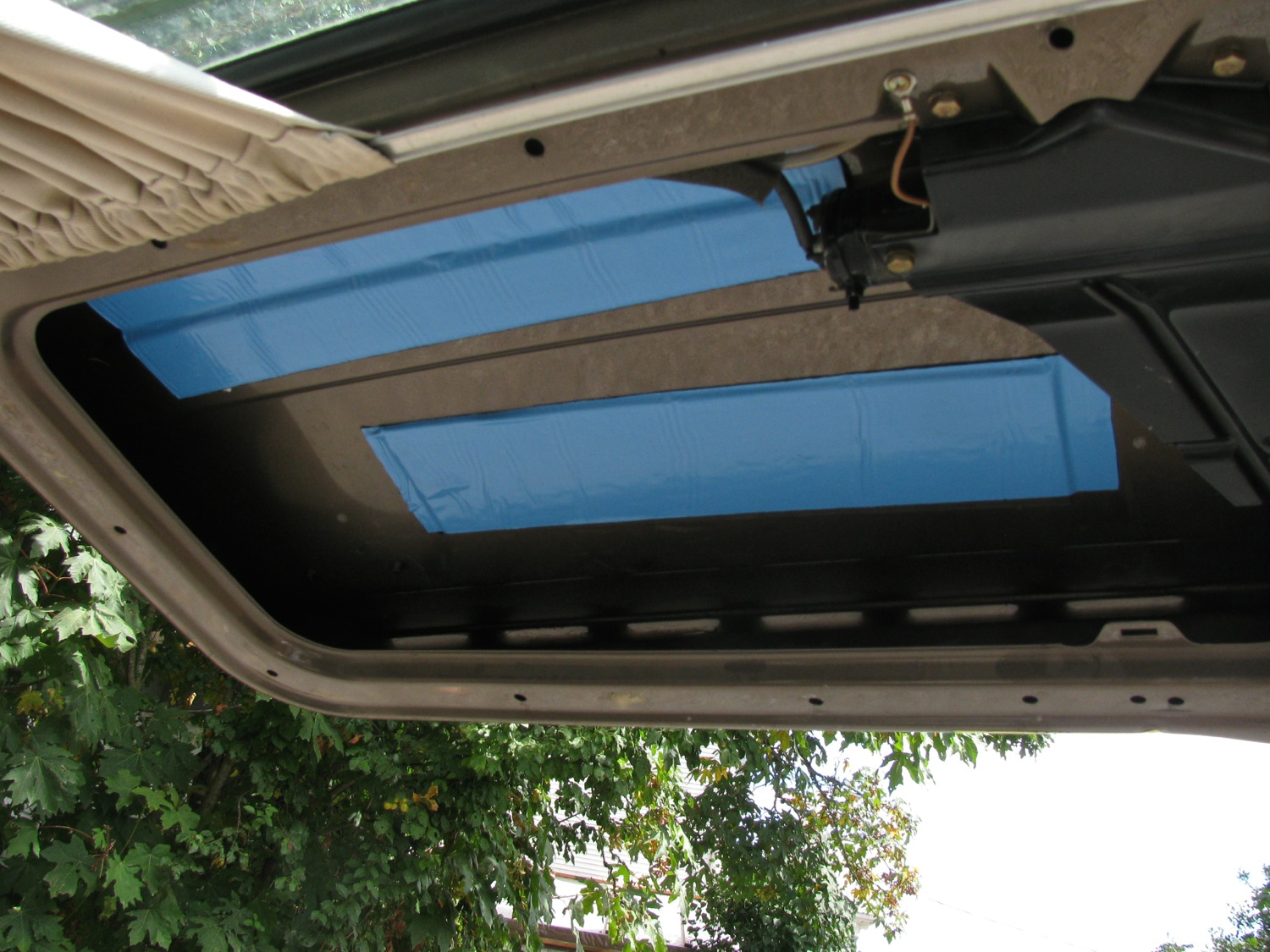
And just because i had some, i pushed in some 3/8″ thick closed cell foam. Left over pipe insulation stuck on lip of cut out.

I liked how it went in, I think I’ll do more of it.
Vanagon – sliding door rollers replacement
Posted by albell in vanagon, vanagon mods on September 8, 2014
About 2 months and no blog posts, sheesh, the next few posts will be playing catch up.
The 85 model year and newer vanagons have a much improved sliding door. Easier operating and a bit quieter than the old style but I thought it could be even better. I had tried UHMW polyethylene tape on the surfaces that the rollers ran on would be the ticket, blog post about that here. But the tape wore out after a year and a bit.
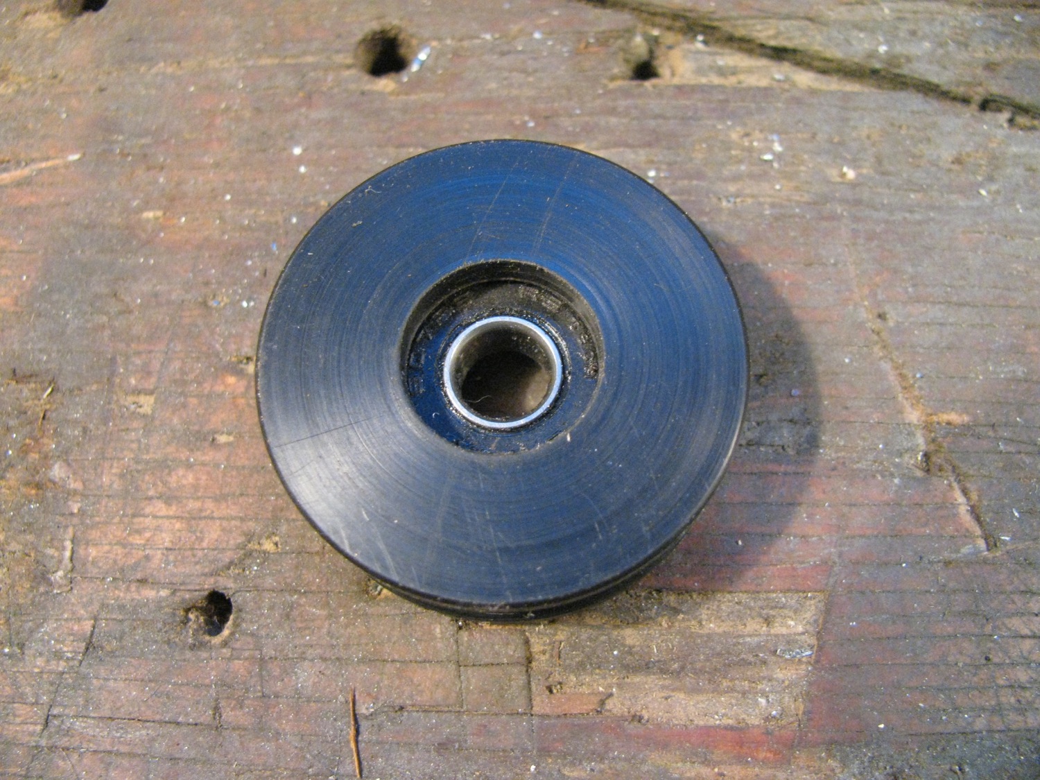
So i thought about a plastic version of the steel rollers. I made a quick and dirty prototype from some Delrin to try on the middle track (the track under the cover on the side of the van).

Not quite an exact copy and a bit out of focus. Here it is installed.

Verdict? Well it is quieter than the steel roller and it rolls just as easily. But with that track silenced a little, now I could hear the lower track roller noise. So some time later I set about making another middle slider roller and seeing what I could do about the lower track roller.
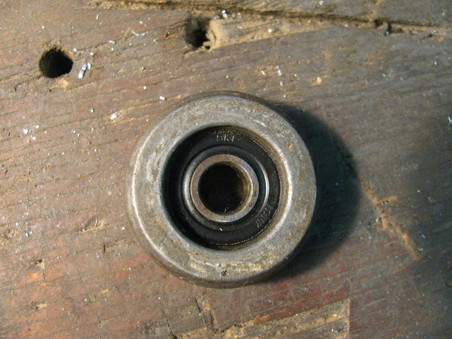
Middle roller, more care taken. Oh, I should mention that the bearing used in the roller is a 607RS. Dimensions are 19mm OD, 7mm ID, 6 mm thick, and rubber shield.


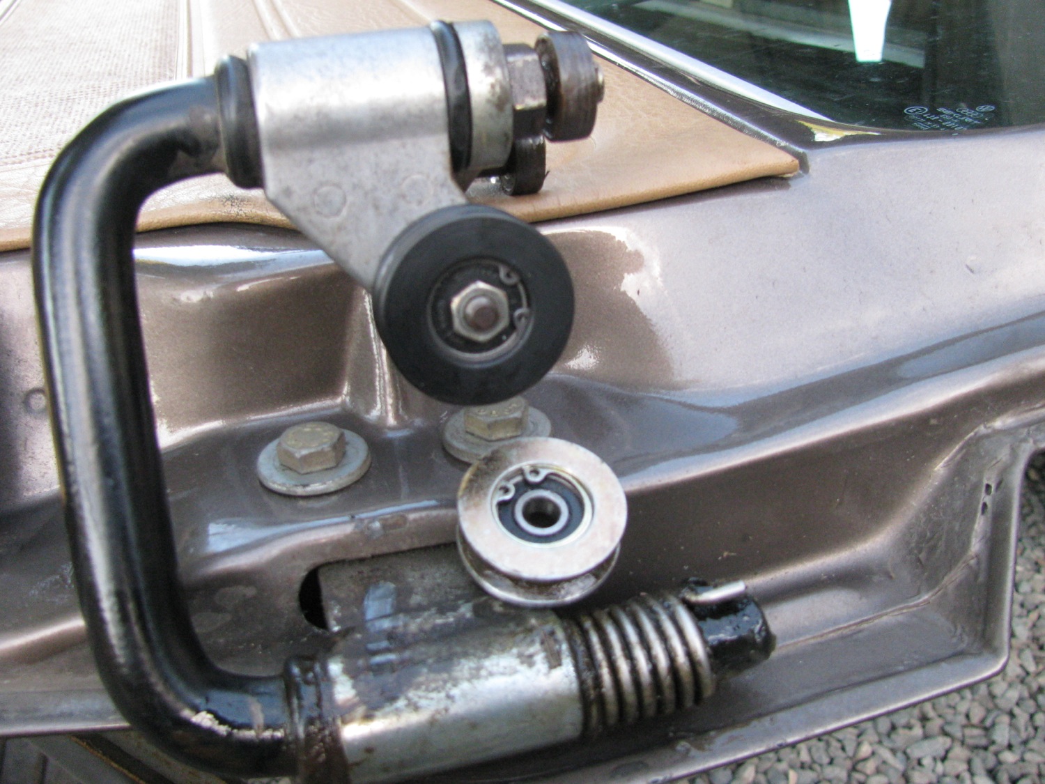
I took the sliding door right off as I was working on the lower roller at the same time. Here is the stock steel roller.

And my Delrin version installed. See the 2 other bearing above the plastic roller? They run in a vertical channel above the rail the main roller runs on. I didn’t do anything with them, but i probably should have thought about it.
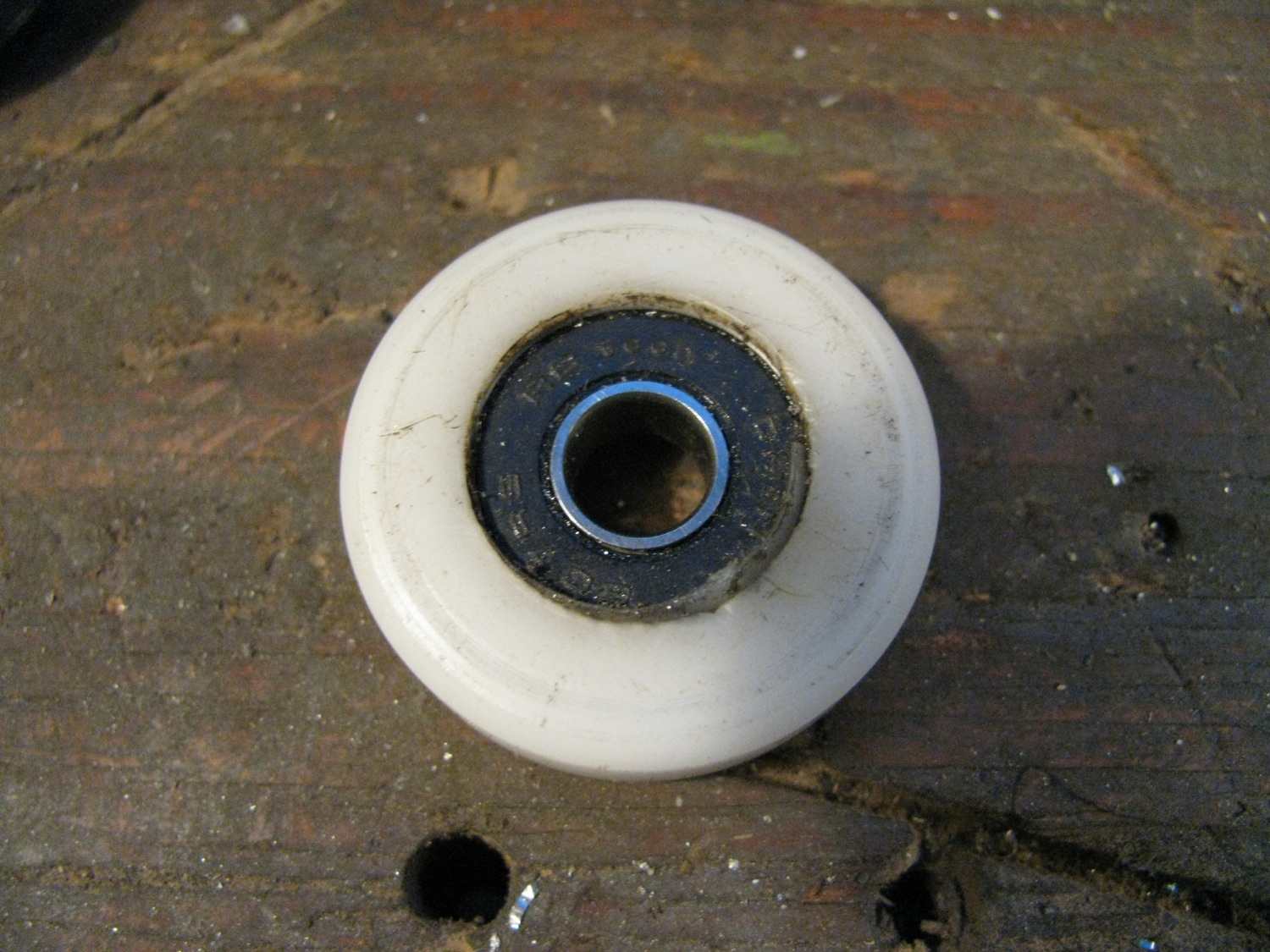
I was going to make a lower track roller from scratch but I found a plastic roller in my junk pile. I think it was from a hanging door, but I can’t remember anything more about it. I wish I did because it is very close to the stock roller dimensions. I just had to reduce the OD by a few millimetres and replace the bearing with a 607RS. It originally had a 6mm ID bearing. The circlip retaining the bearing was a real bear to remove and I accidentally broke a little of the plastic.
here is the stock steel roller. The roller is on a post on the lower assembly , secured by a circlip. The plastic shield can be pried off and the clip removed and the roller pulled from the shaft.

This is not a roller with a pressed in bearing, the bearing and the roller are all one piece.
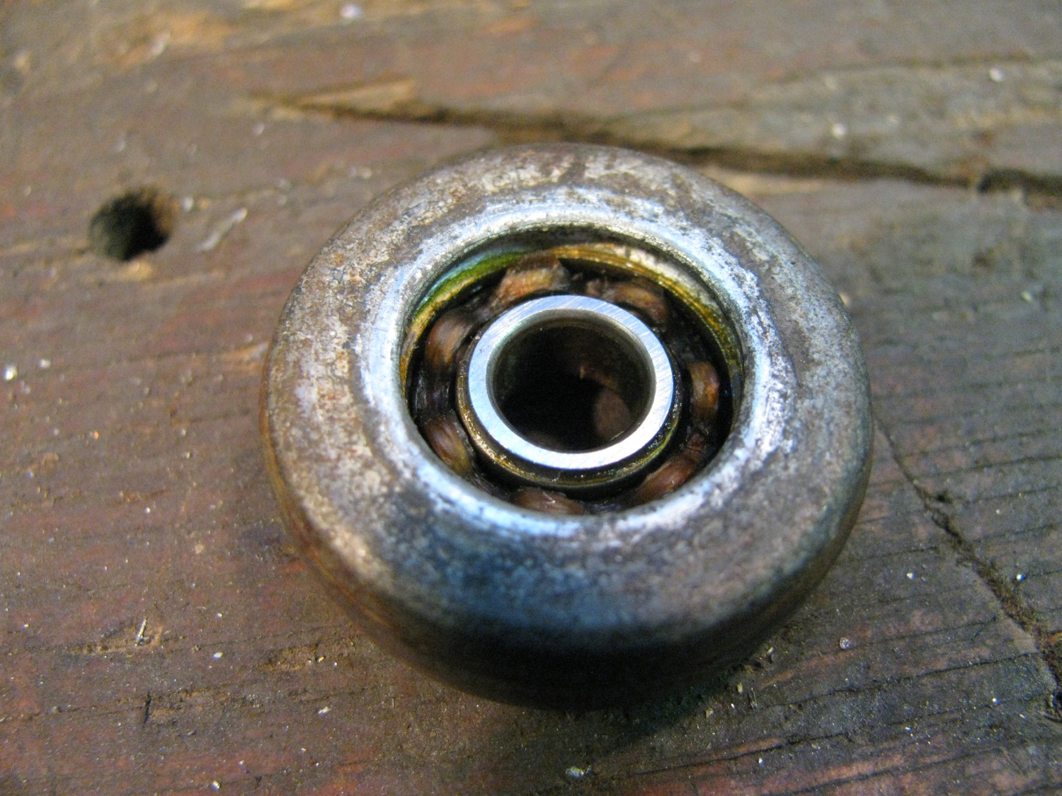
Has a rubber shield on the inside, the bracket side, face.
Comparison of the stock roller and the hanging door roller. Both have somewhat similar profiles. Close enough for me anyway. But as I mentioned before, I had to turn down the OD of the plastic roller.

Plastic roller with new bearing installed
And showing where I broke the darned thing.

And there it is installed on the door bracket.
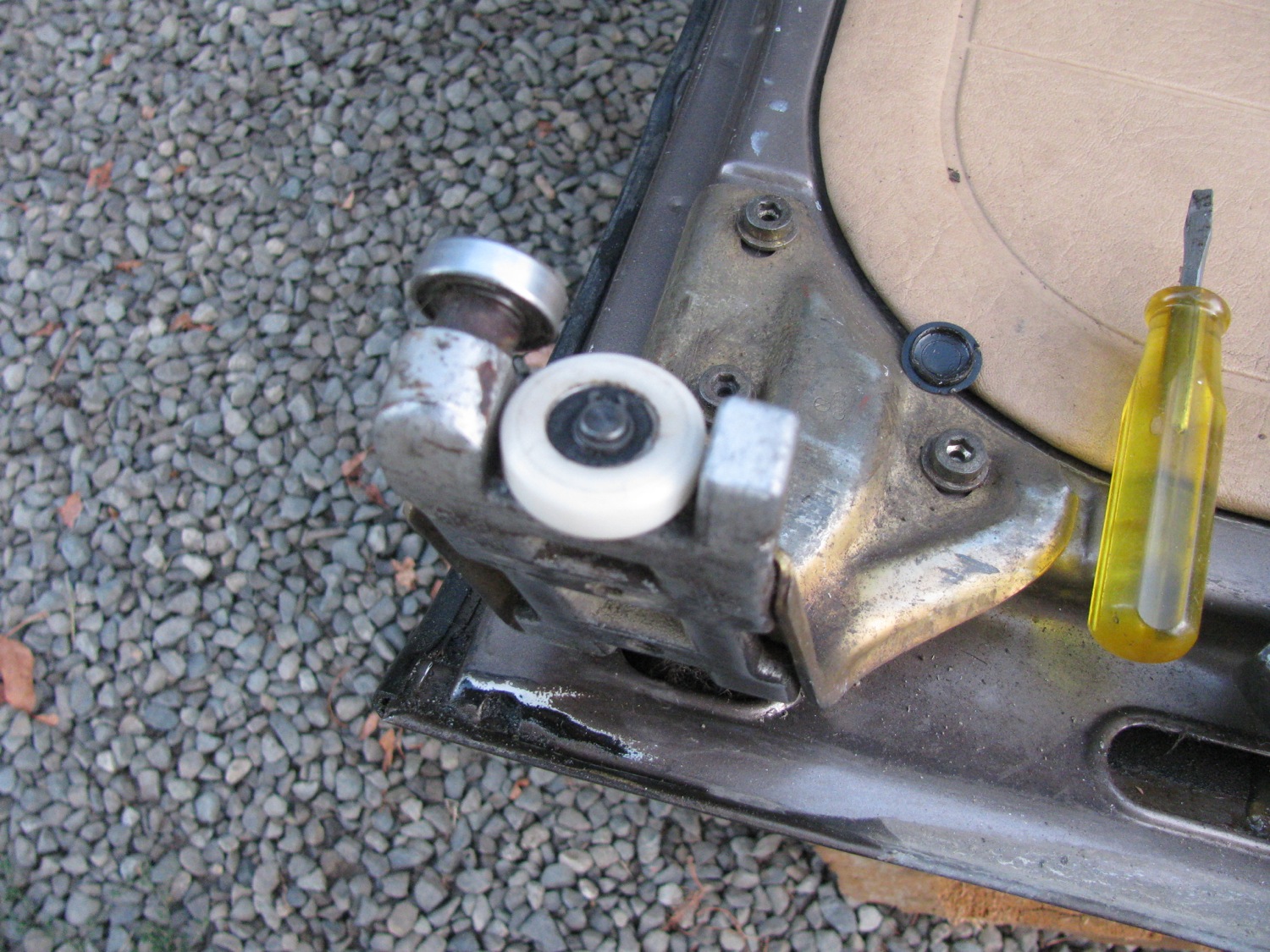
So did it make a difference? Yes, it did. Again quieter and smoother. The door still is not as quiet as I would like and I think some of the noise is coming from those vertical bearings on the middle slider, the pair I should have paid more attention to.
You know, this is the kind of project that 99.9% of people would look at and shake their heads, mutter “get a life” and then wander off to chat with someone else. It is only when i sit down and write this post does that realization sink in.
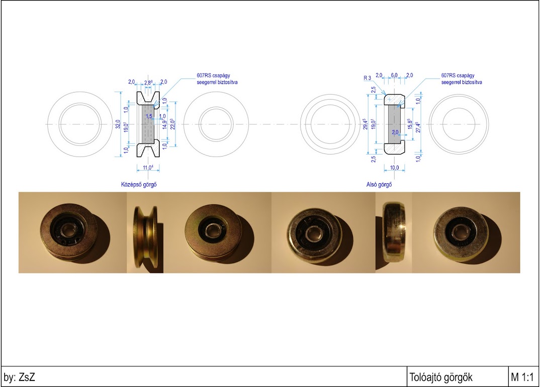
Crikey, forgot to add an important thing… to thank “ZsZ” for posting measured drawings on this Samba thread. I’ll be cheeky and link directly to the drawing.
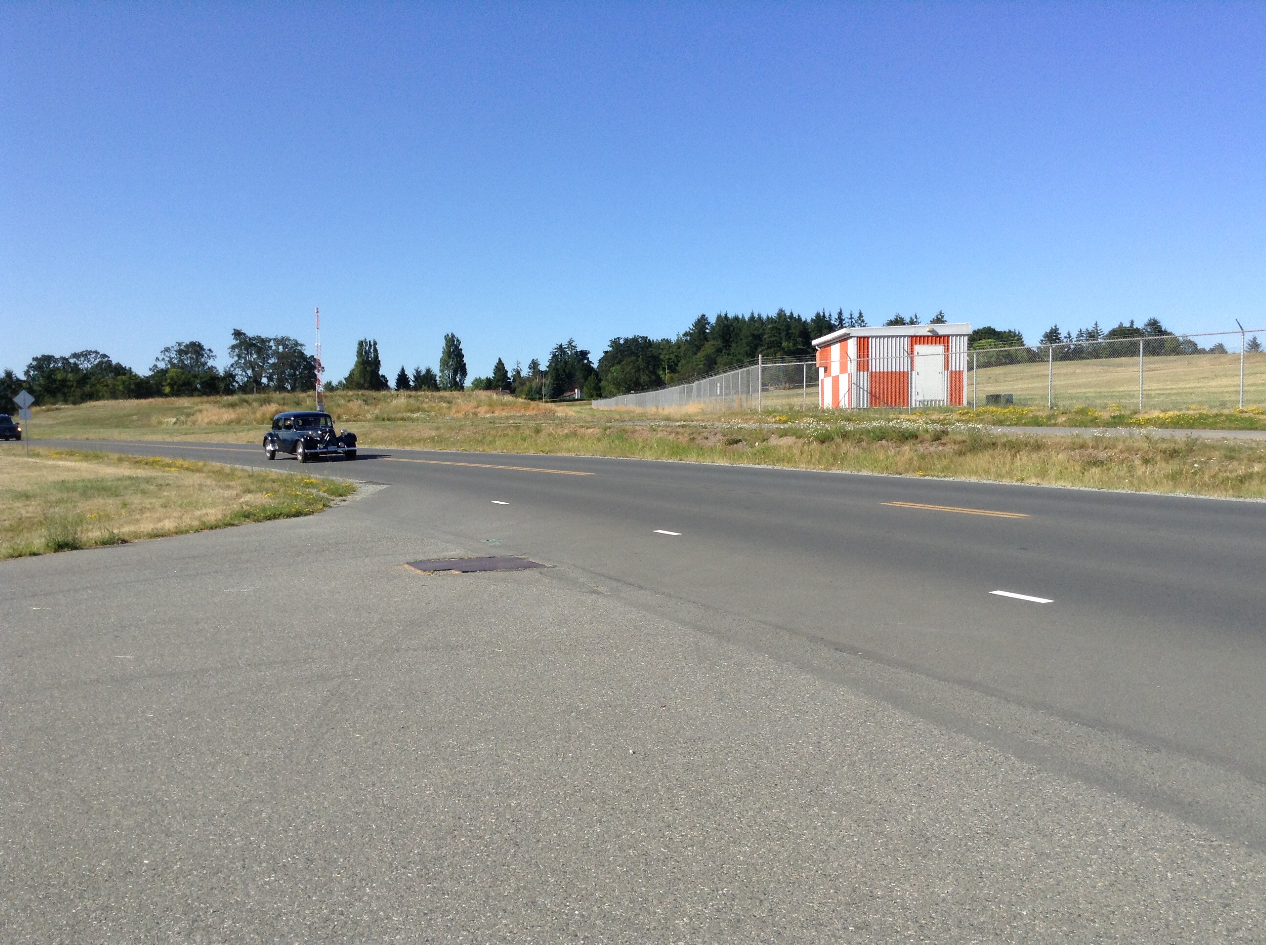
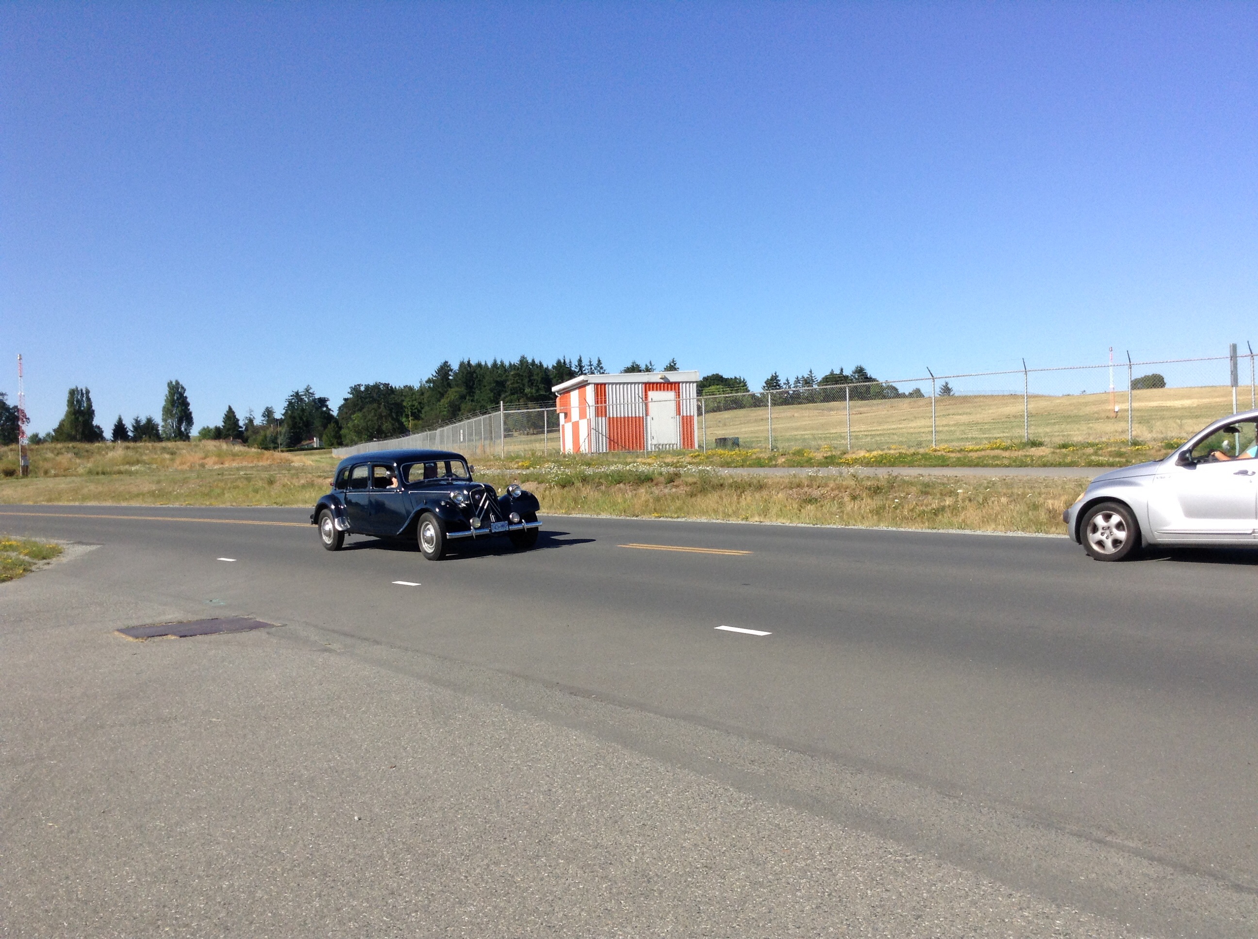
Seen on the way home today
Posted by albell in other cars on July 7, 2014
Noticed it at intersection to road I was driving on, pulled over further on ( right where float planes get ferried across from airport to Patricia Bay) and grabbed the iPad mini from its mount.
You know, there are quite a few interesting cars around here and they come out in the good weather. But I don’t often get a shot of them on the road.
So distinctive, so very cool, such a loaded history.

Trip – turned out to be more of the same
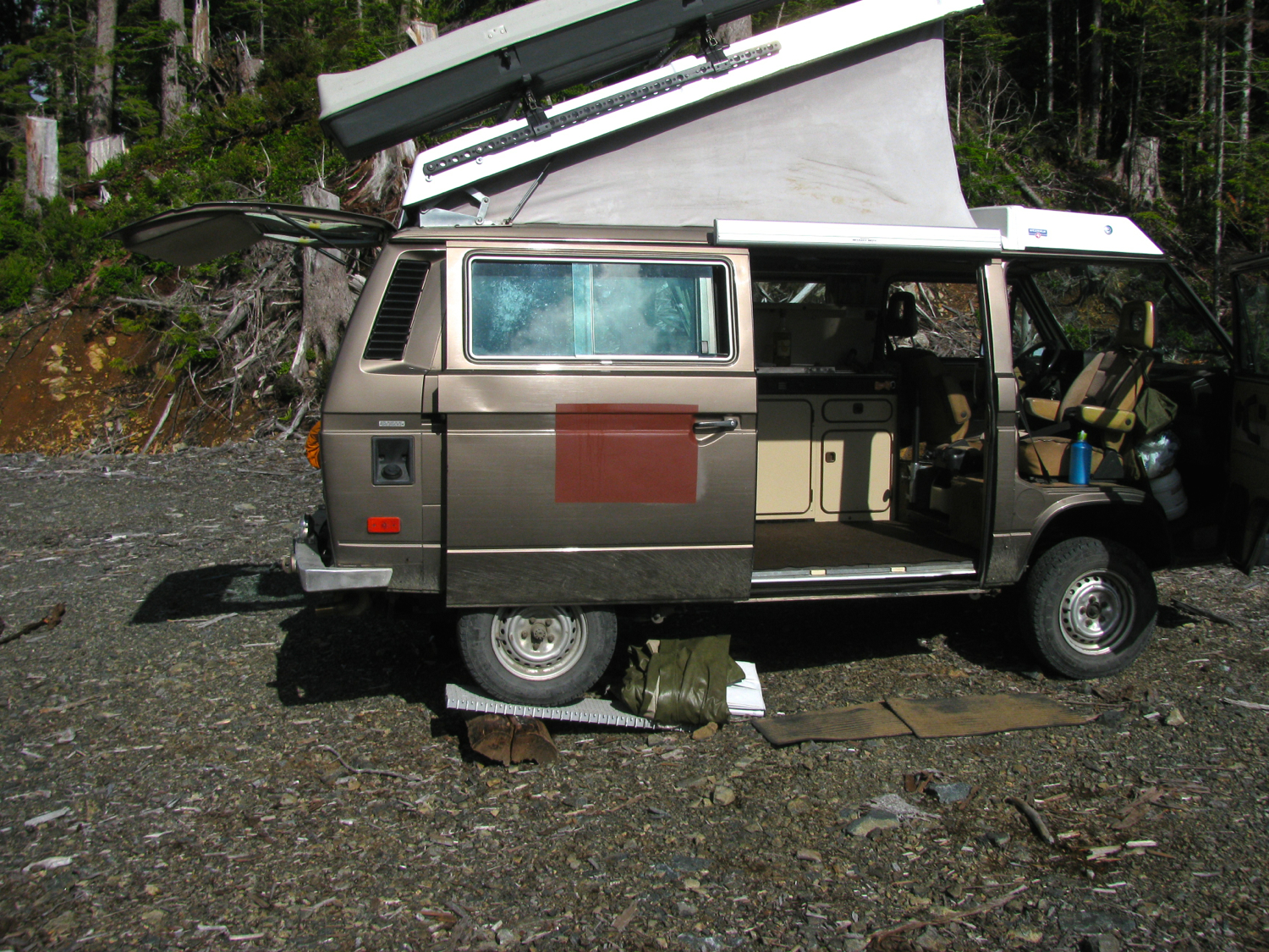
We were planning on exploring some new areas when we left late Sunday afternoon but were thwarted by closed gate on the access road. Where there is active logging the contractor usually restricts access to the area by locking a hefty steel gate across the road or even just a steel cable with signage. I think they do that mainly to reduce chances of vandalism or theft of machinery or equipment left on site during non working days. So we headed up to one of our fall back view point spots while there was still heat in the day and we could sit back and enjoy the view and some beverages.
So there we were, again.

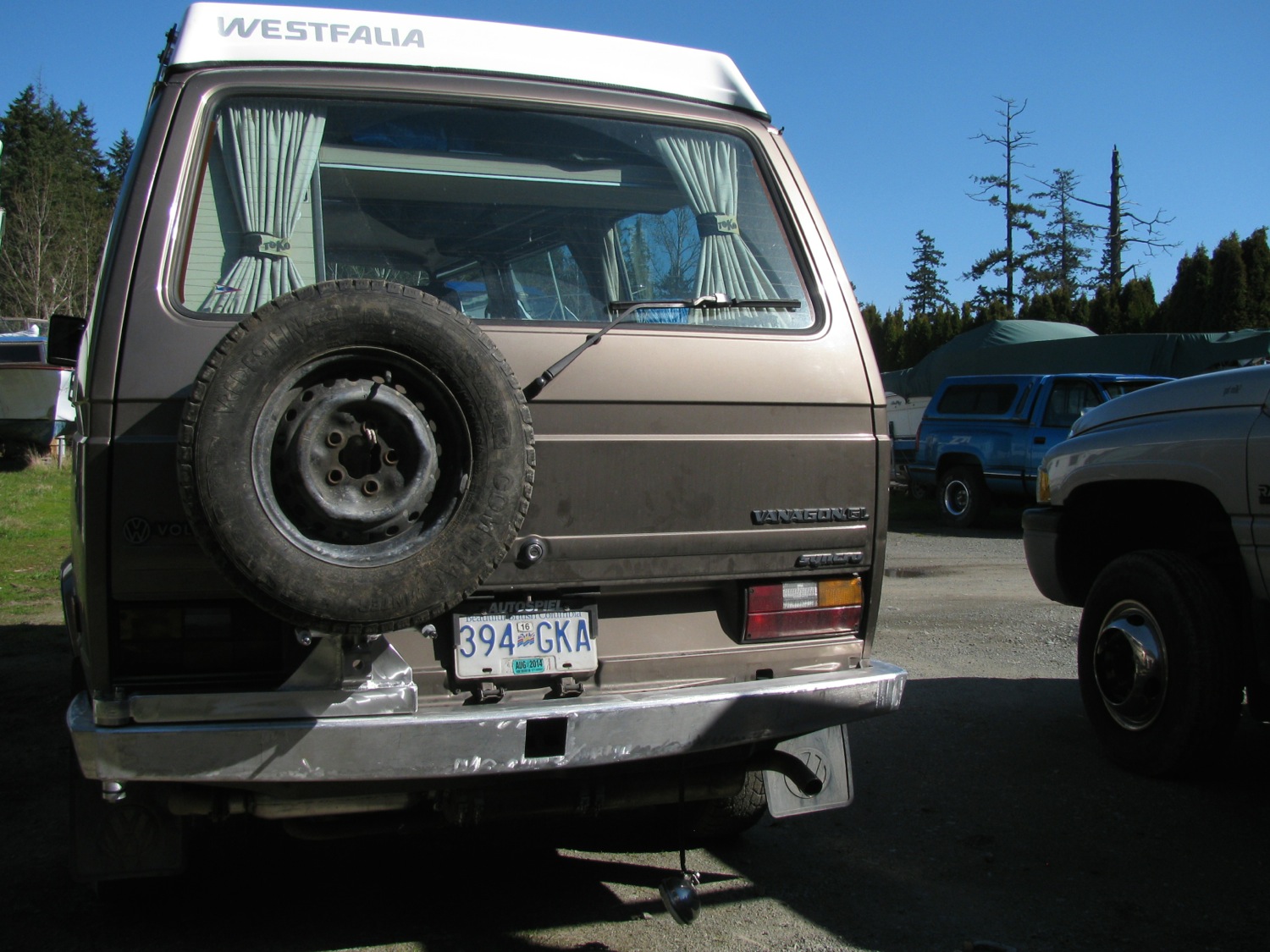
Bridging ladder used to level the van. My van is a rolling advertisement for my slowness in finishing things. Sliding door skin repair, rear bumper build (well it is getting closer), still no tires for the 15″ alloys I bought a while back.
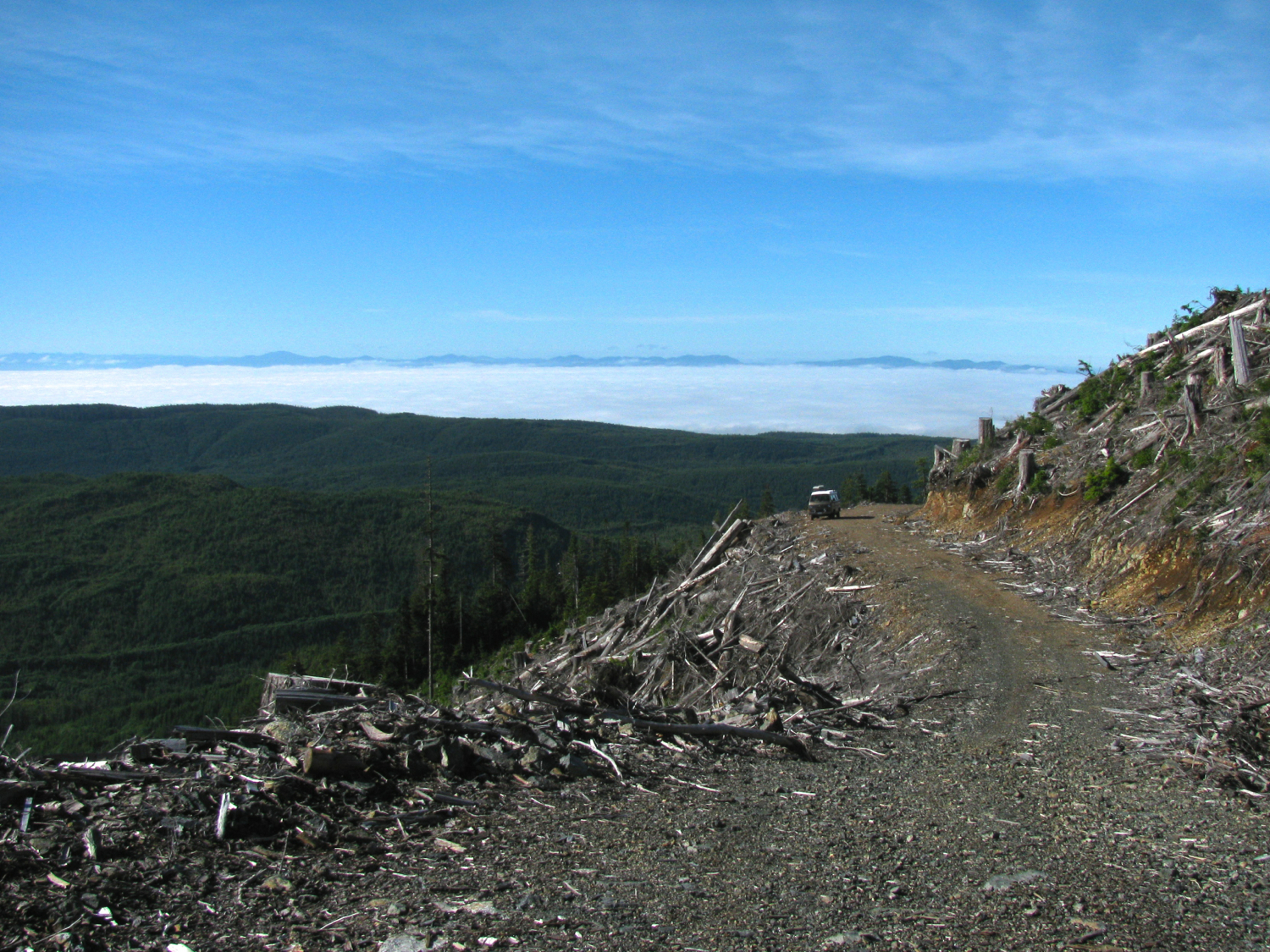
Took a walk, into newly logged area. I was taken by this cloud on the hill.

And took a bunch of pics for a pano. If you click on image it comes up in new tab/window, at my default image size of 1500 pixel max dimension. You might be able to make out the beach at Port Renfrew.

Then suddenly it seemed like someone turned on the smoke machine to film some post apocalyptic movie.
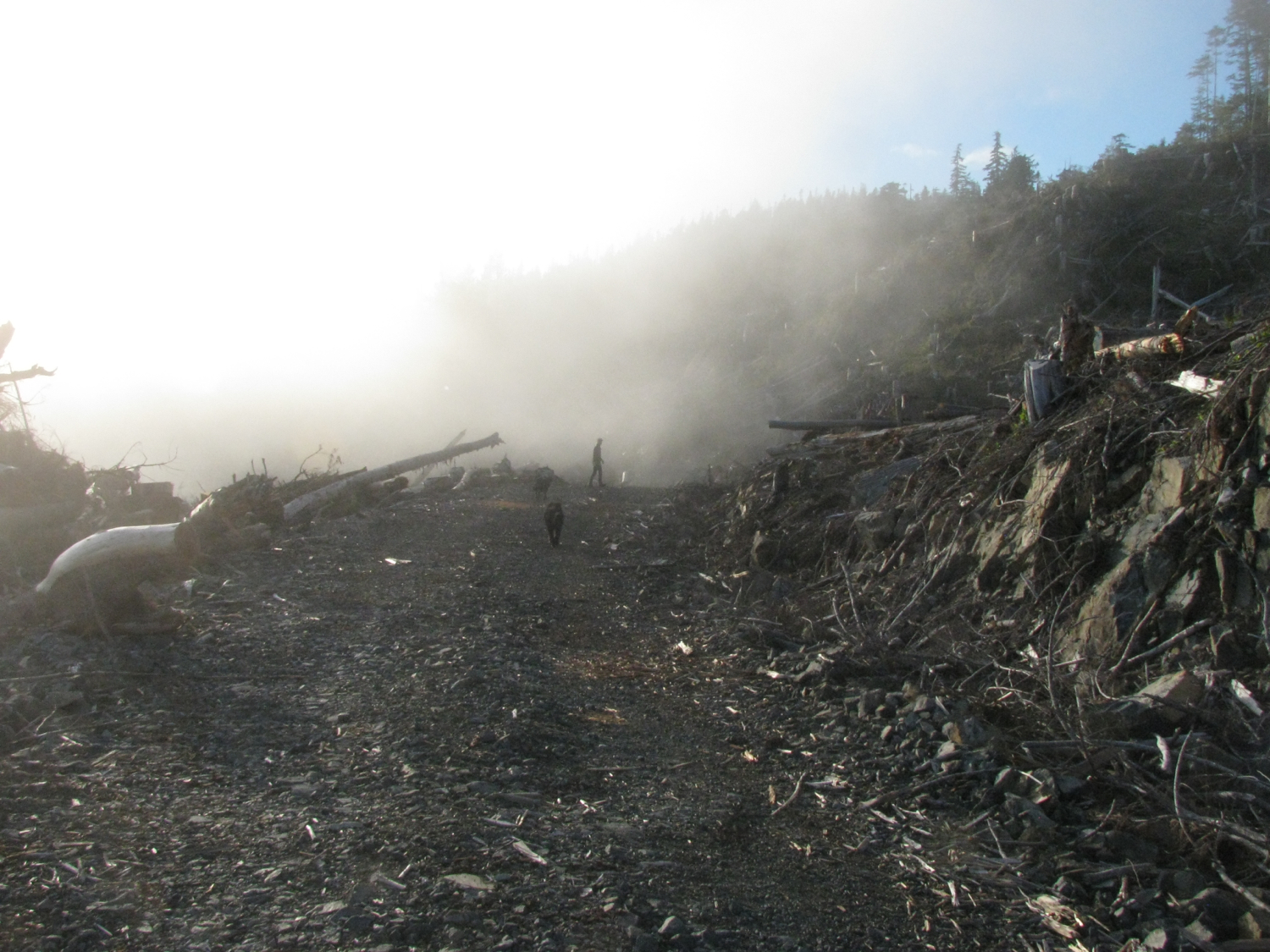
And almost as quickly turned it off.


You know, i never get tired of the view looking over to Washington, summer sunset. You notice the orange haze? Could be from a forest fire somewhere. A couple of summers ago we had amazing sunsets when camping in same general area that were due to forest fires in Russia. Hard to believe eh?
Next morning I got up early and took some more pics to stitch.

We left at about 0930 and made a few exploratory trips up roads like this. But we didn’t find a good spot to camp.
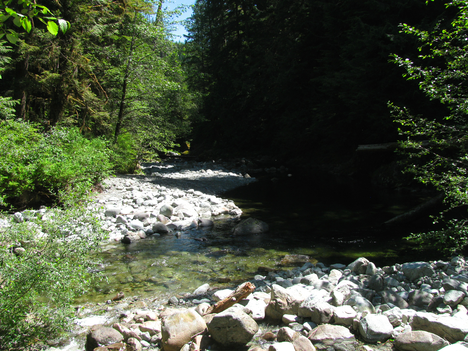
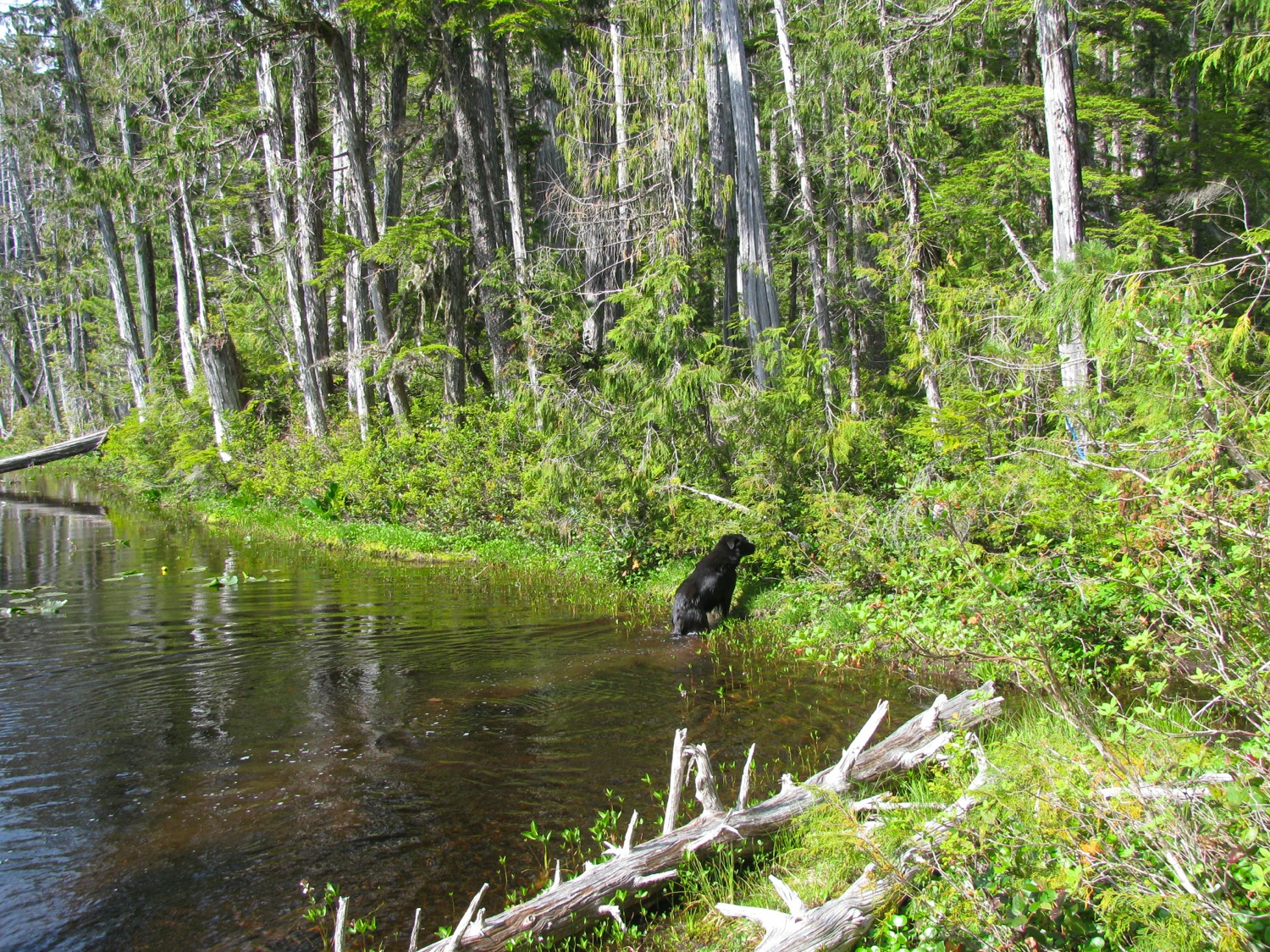
So it was a fall back to Loup Creek. It is pretty isolated, I don’t think many would make the effort over the moderately rough and slightly overgrown road just to be able to sit on a bridge. No, I’m not picking my nose.

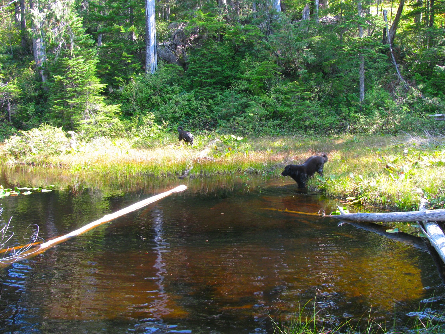
The creek is beautiful, but quite cold. We hiked around, exploring a few km upstream and a little ways downstream. Here are a couple of pics of a little feeder stream, posted to point out a couple of things. First is that I find it really hard to take a pic of theses streams during mid-day. The river rock reflects light, the shadows and greenery suck the light up. I think i would have to set the camera on a tripod and take a series of pics with varying exposures/aperture and sam them together for an HDR image.
Second is that these short steep streams on the west coast of the island vary in flow tremendously.
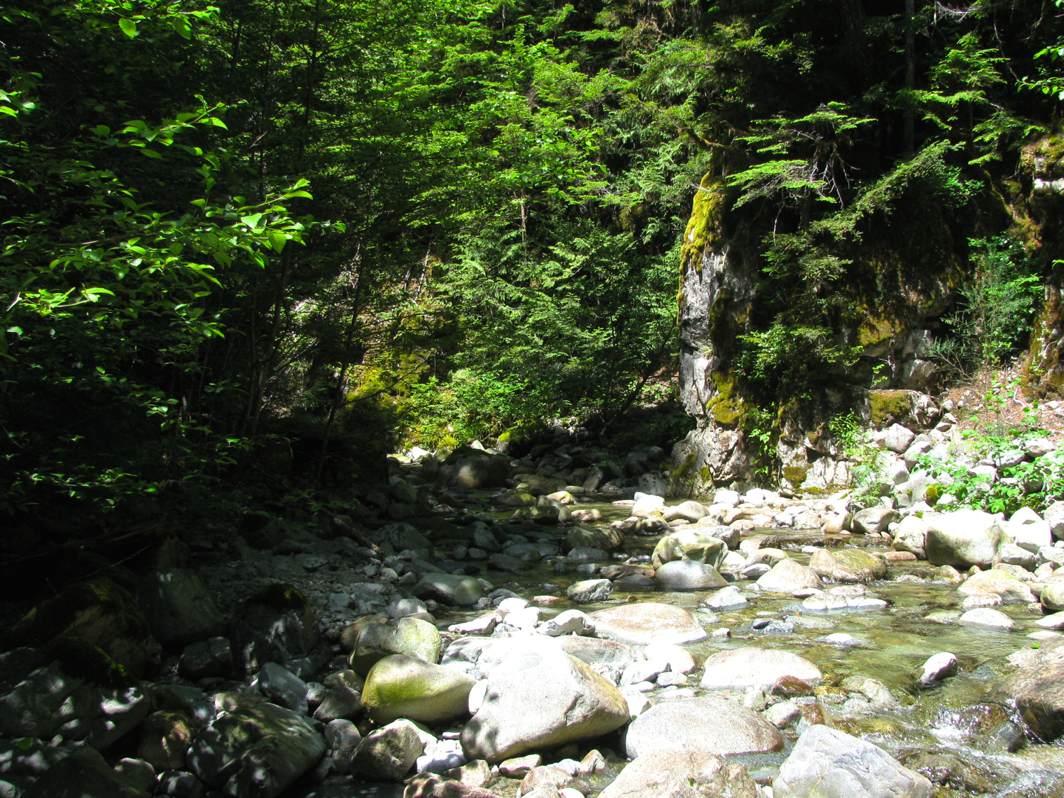
You’ll find debris high up on the rocks or the bank that was deposited during floods.

All that white rock would be underwater during winter spate.
Supper time on the bridge. Chairs now on south end to catch the sun.

Eco-Que being used. Marinated chicken on flat steel skewers. Still haven’t used the grill surface of the Eco-Que. Yeah, just nine briquets.

Lid on to finish cooking.
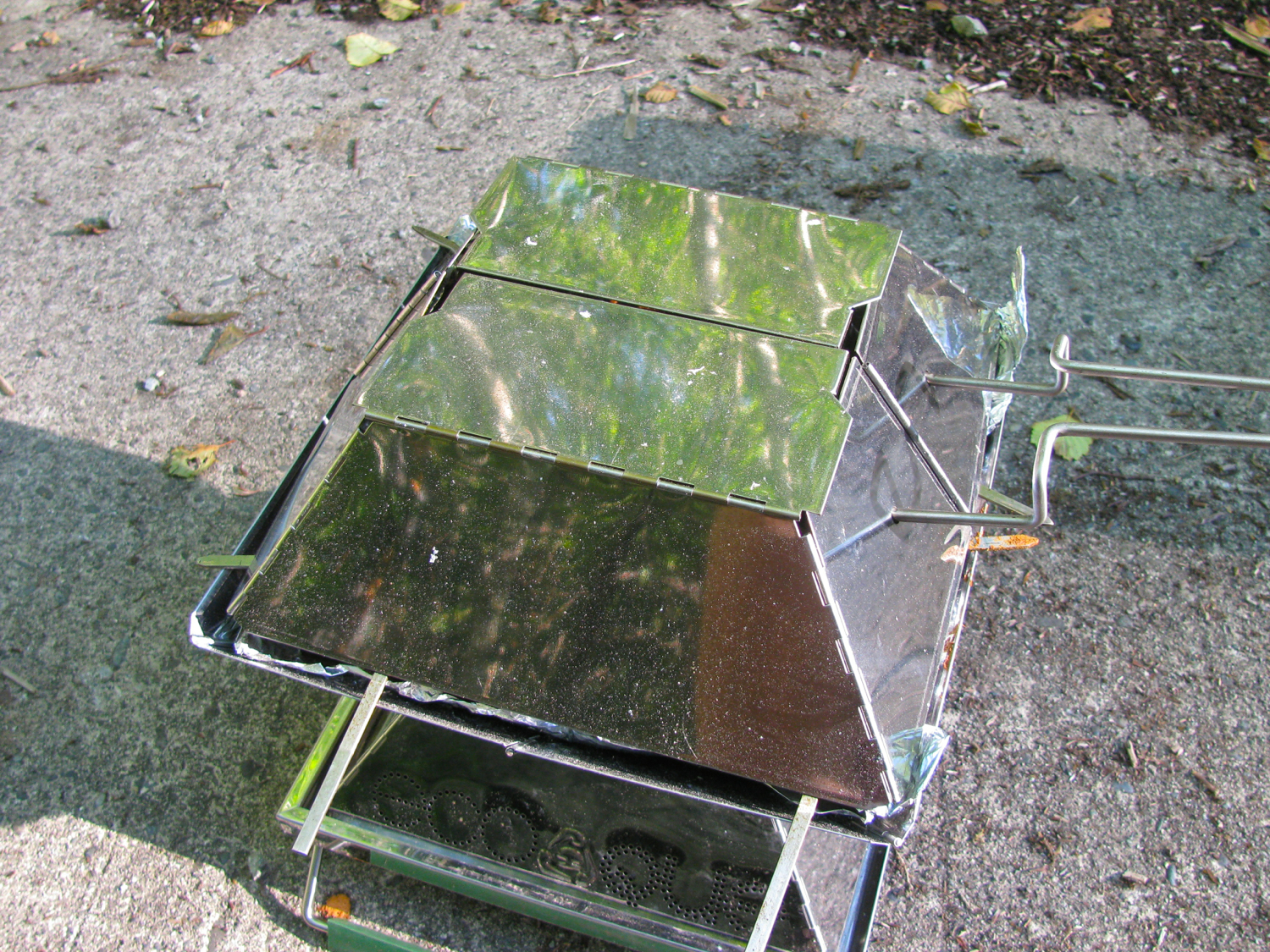
Had this canvas bucket for years, US Army issue, one of the most useful accessories.

Next day we explored more, sunbathed more, read more, drank more, ate more, dunked in the frigid creek more, and then drove home in the late afternoon, early evening. Van ran like a champ, fridge worked from when it was lit at leaving on trip to when we got home. Garmin Glo and iPad mini remain a superb navigation combo – I should do a post on the software I use.
Vanagon – syncro clutch slave cylinder replacement adventure
Posted by albell in syncro, syncro specific repairs, vanagon on June 21, 2014
Seems to be a real busy time of the year for me, just the time to put a new slave cylinder into the old syncro. It had been leaking for a few weeks, but it still worked the clutch. I procrastinated replacing it until I felt like hurting myself.
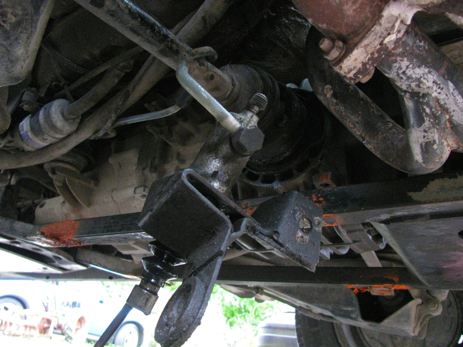
I’ve swapped in a slave cylinder a couple of times on a 2wd vanagon, I4 powered ones at that, and it was not that bad. But the stock motor in the syncro makes access to the bolts holding the slave to the bracket really painful. The rear most bolt is somewhat accessible front he engine compartment but the nut for that bolt is pretty well hidden by the bracket. A good fix for that is to weld that nut to the bracket so you only have to deal with the bolt and no need to hold the nut. The front bolt is somewhat easy to access, from under the van. I tried to get those bolts off, but I couldn’t. I even bent a wrench to get it in there, but no luck. I had heard that some folk take the bracket and cylinder off as a unit and that means taking the actuating arm off the shaft that goes in the bell housing (and moves the throwout bearing). There is a cir clip on the end of the shaft and theoretically, on a brand new van, when the clip is removed you can slide the arm off the shaft. I don’t see how you can do that easily on any van that has seen any kind of use. The arm is on there but good.
I had a spare arm (and shaft) so I decided to grind the arm off. I used a steel burr on a die grinder. Yes I chewed up the shaft, I got sloppy. But I didn’t do enough damage to make the replacement arm a poor fit, still went on tight.

I tagged the bracket too.

The arm.

Now it was just a case of removing the 13mm head bolt on the bracket support strut and the 17mm bolt holding the bracket to the bell housing. Then you can ease the assembly down and let it hang by the hydraulic line. Great thing here is that the syncro has a flexible nylon line to the slave (and banjo bolt) rather than the steel line of the 2wd.
I had the new, FTE brand, cylinder already to go, bolted to a spare bracket. A bracket from a diesel vanagon… yes, you know what’s coming.
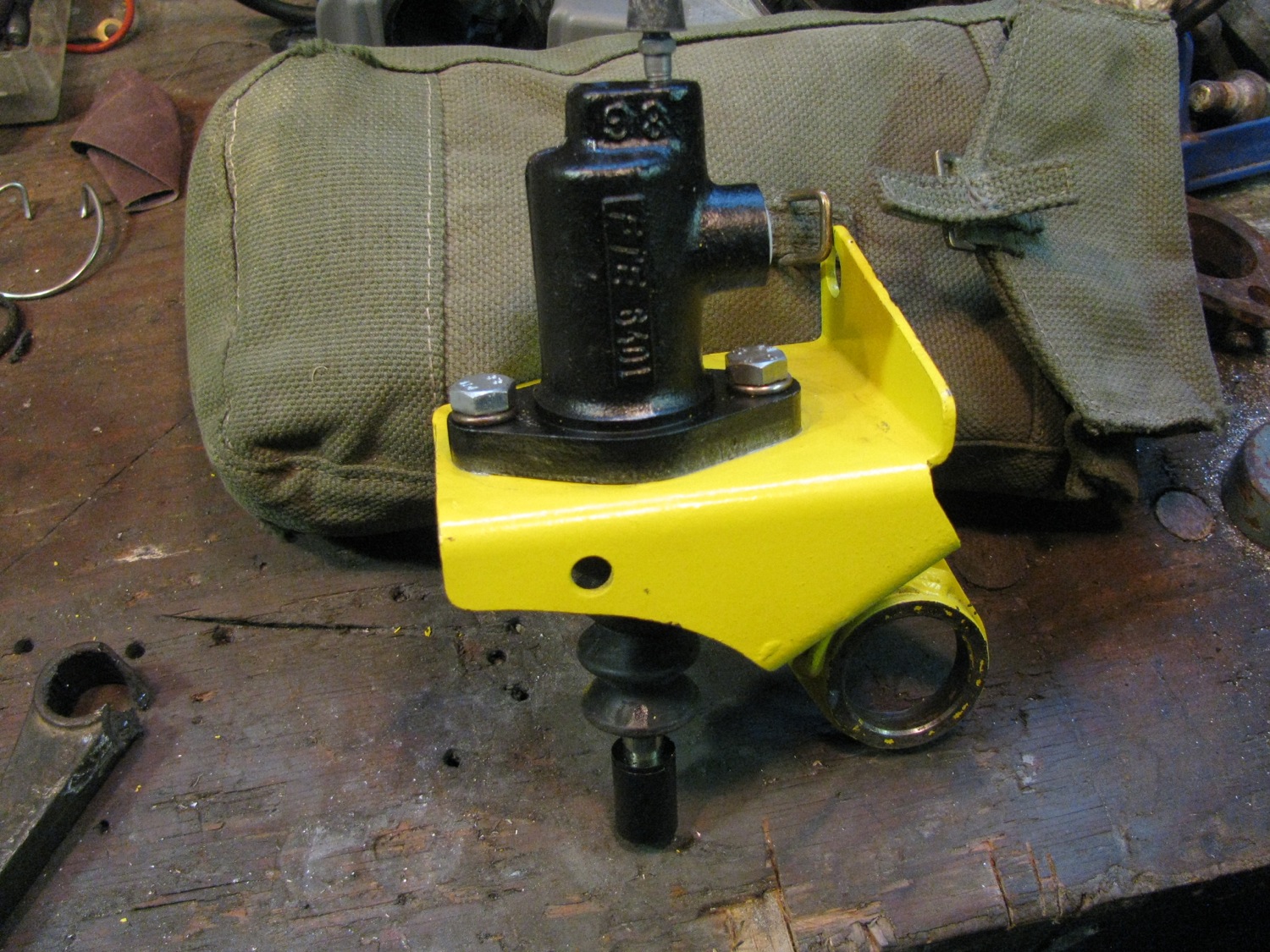
I had welded the two nuts to the bracket, here is a pic of the front nut. Yes, you know what’s coming.

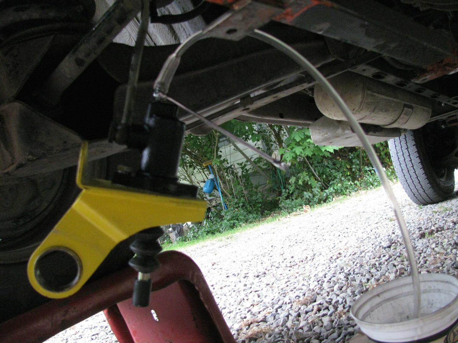
Quick with the swap over and now bleeding with the cylinder hanging.
And up it goes into position… except I forgot the support arm is held to the bracket by that front nut which I had welded on. Doh, what a bonehead, ok off it comes with the zip disk. Right, up again with support arm attached…except it didn’t fit. The support arm would not line up with the bolt hole in the transmission. Son of a bitch. Out it comes, let’s compare with the old bracket.
Gee, whaddya know? They are different. It takes a special kind of bonehead to assume a 2wd diesel vanagon bracket would be the same as a wax syncro bracket. I am that special bonehead.
And, to add insult to injury, after cleaning off the muck from the bracket I could see someone had brazed on the rear nut and had brazed on the nut to the support bracket. So i could have removed the slave by itself after all. Well, no, not really. The bolts were in there real tight. Even with the bracket held in a vise I had to grunt with the spanner to remove the bolts.

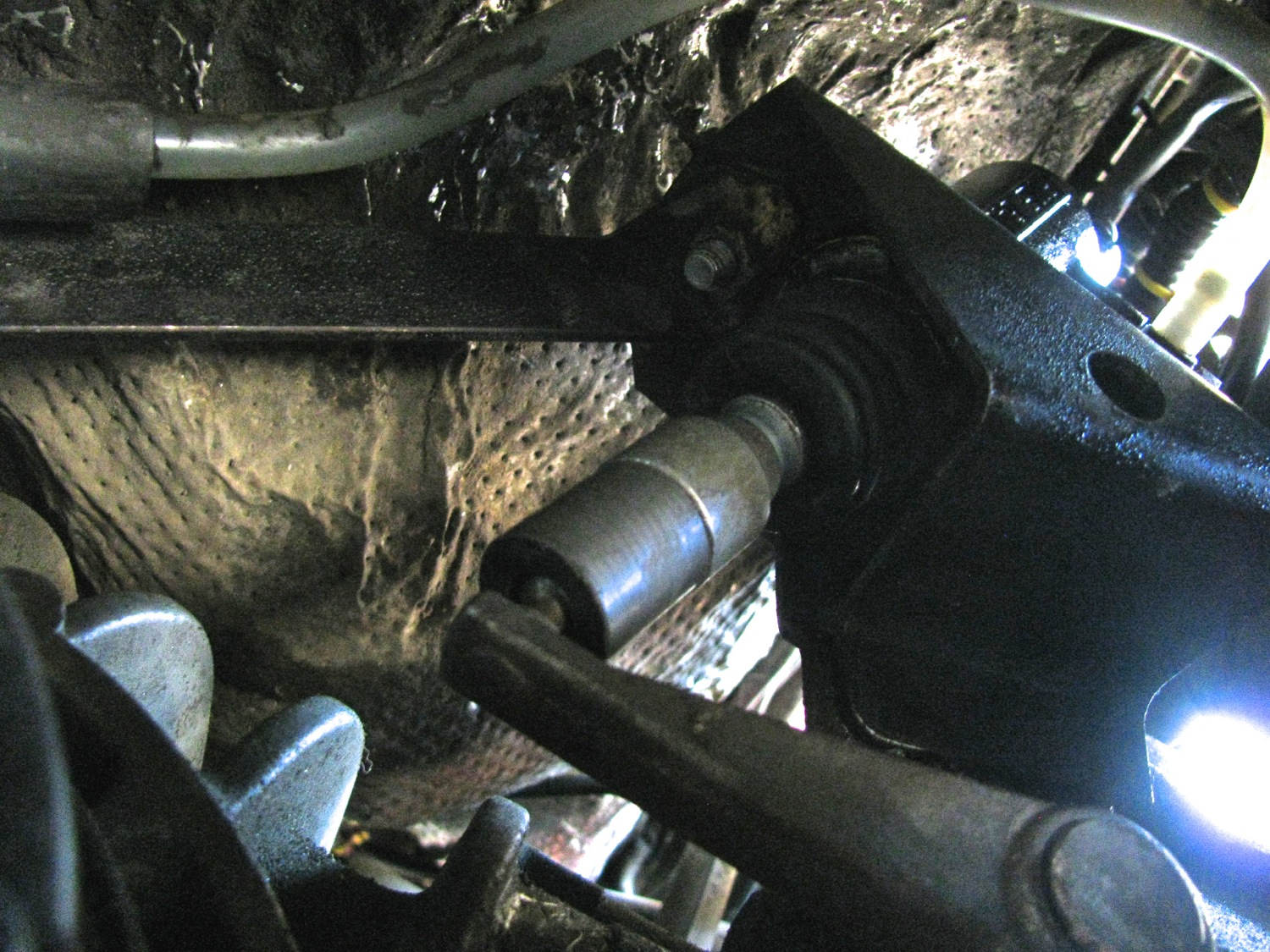
Righty oh then, back to the van to install new slave and old bracket combo. All went well, replacement arm on shaft, cir clip in place, slave bled. I tried the clutch pedal. The friggin pedal stopped hard about 2″ above where it should stop, no clutch activation. What the heck was going on?
The arm would move when the pedal was depressed, but only a little way before the pedal felt like it was hitting metal. I pulled the push rod from the slave and compared it with the one from the old slave, it had a longer effective length. New push rod at the bottom of the pic.

With the rod removed the clutch pedal would not move, with the shorter old rod the clutch pedal would move down a bit, with no rod and the bleed screw open on the slave the pedal would press down full range. Can you guess what was up? I couldn’t at that point. I talked to Dave the mechanic, we both were stumped but were leaning to an internal problem, perhaps the throwout bearing retaining springs had come adrift. Looked like a tranny pull. I was so desperate that I looked on the Samba and found something interesting, here is the thread. Now I had some hope, so I quickly made a bit of an extension using the old rod (I removed what remained of the plastic that was inside the metal cup end) and some polyethylene.


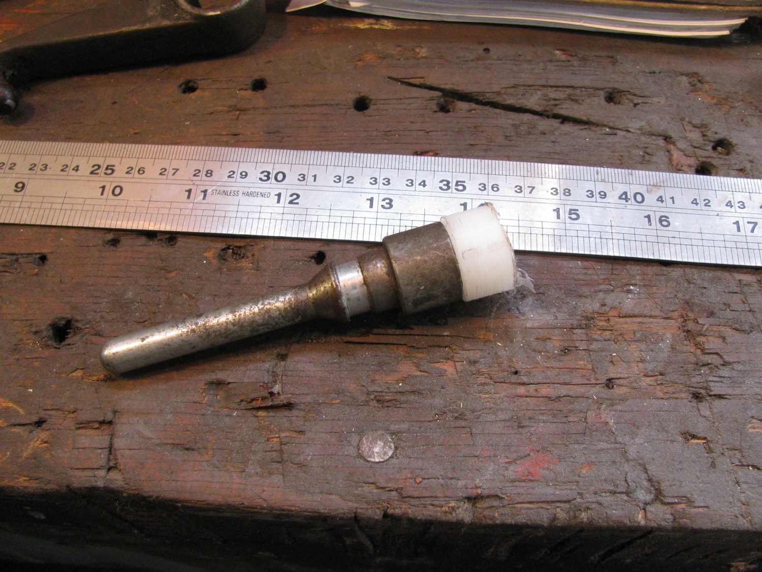
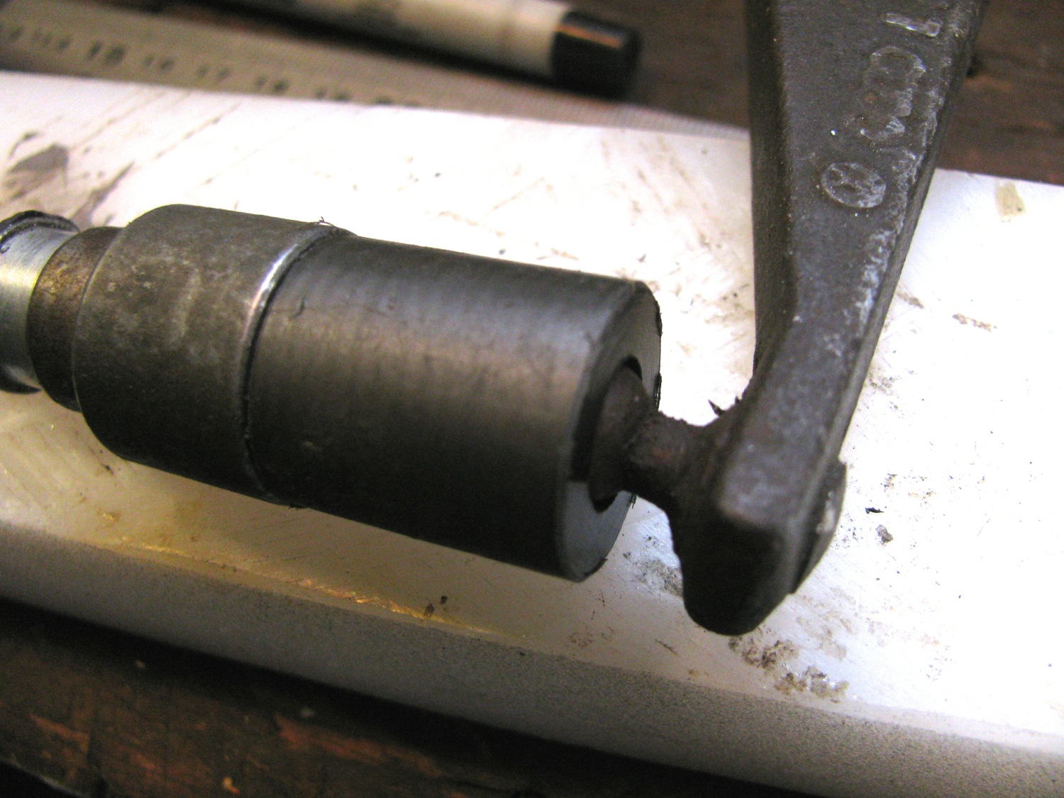
I made a hole, stepped hole, to mimic a socket to engage the ball on the lever arm. I installed it and yes, more pedal travel. Not quite enough so a made another using some Delrin rod. Here it is. BTW, it is a press fit into the metal socket.

And, yes, success. Clutch works just like it used to, perfectly. Man, I was relieved. The modified pushrod had overall length of 112mm, socket in the Delrin was 4-6mm deep giving an effective rod length of 106-108mm. That’s 18-20mm longer than the new FTE push rod.
So what the heck was going on with the new slave? As I didn’t want to take it out and measure I can only guess that the new slave had a shorter piston stroke than the old one. And even with a longer push rod it was not enough to fully activate the clutch. And before you ask, I did have the slave cylinder properly installed in the bracket. I wonder if the syncro bracket locates the slave higher from the arm than the 2wd bracket?
Trip – finally out for an overnighter
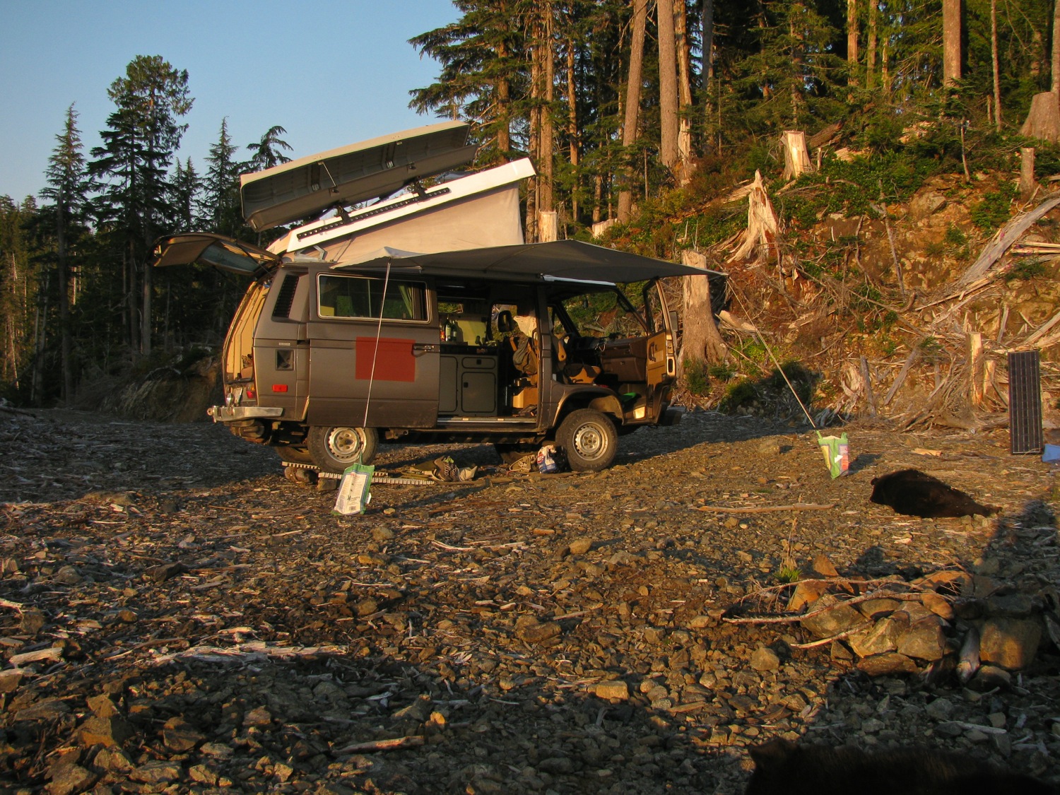
What with one thing and another we haven’t got out for a vanagon camping trip this year until this last weekend. Was just a quick overnight trip to, once again, the Port Renfrew area. Here are some pics.


Marine cloud started to move in around 5 pm. By sunset it was at our camp (654m elevation).


Cloud in the valleys next morning.

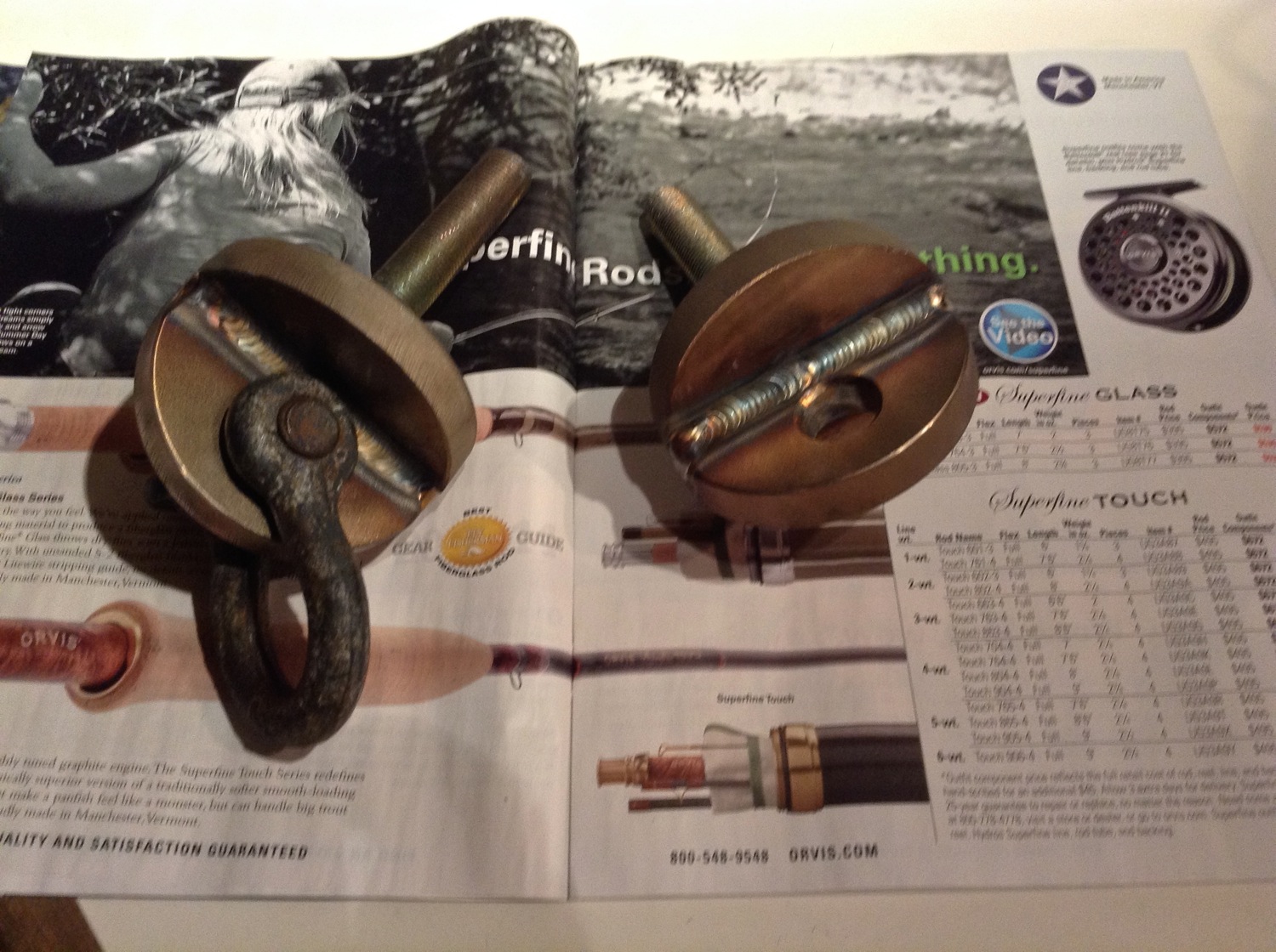
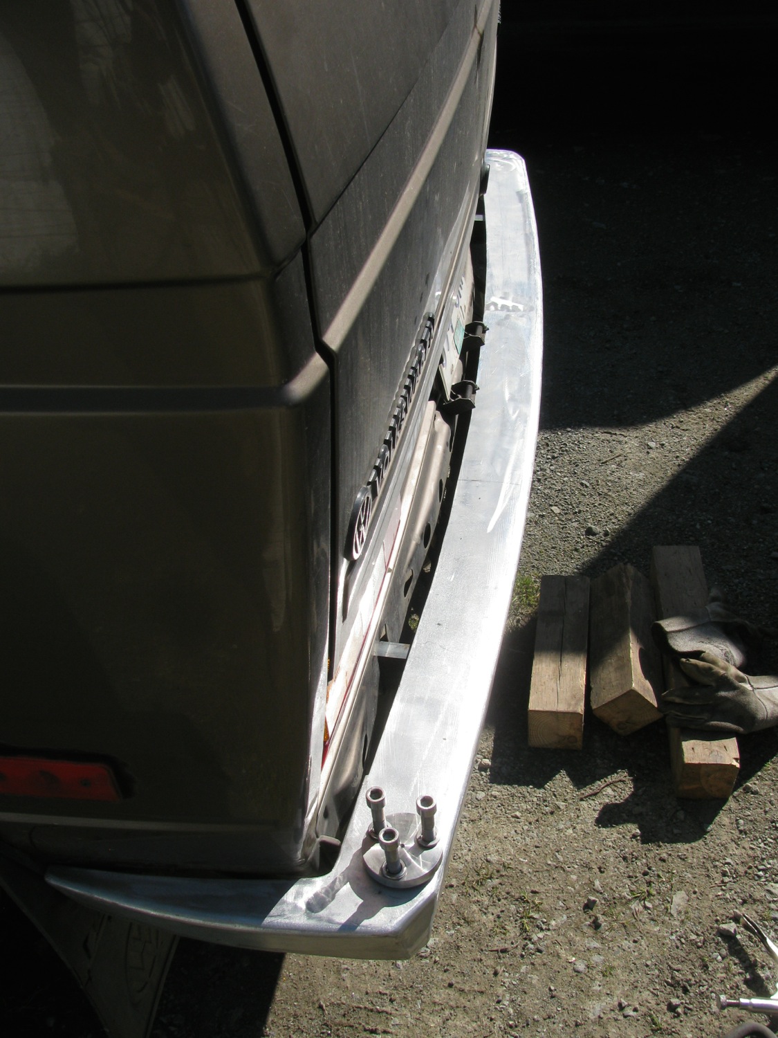
Finally, a bit of a bumper project update. You might notice i have the unfinished aluminum bumper on the van during this trip. It’s on and off as I fiddle with things. My most recent fiddling was making some tow hook brackets. These will screw onto the bumper where the steel framework for the hitch attaches to the van. The brackets are made from some 1/2″ stainless steel disks, 3″ in diameter. They were water jet off cuts. I cut one disk in half, drilled a hole in each semicircle. Two disks had a hole drilled in them and I cut the head off a pair of M16X1.5 bolts and welded them into the holes in the disks. I then welded the semicircle parts onto he disks. Picture shows one with a shackle attached.
Vanagon – new wheels and tire fitment
Posted by albell in syncro, syncro specific repairs, vanagon, vanagon mods on May 10, 2014
Too long i have suffered the jibes from fellow syncro owners about the teeny stock wheels and tires I use. Finally I found some wheels that might let me join the real mens club. They aren’t my first choice but the size, price, and offset were all right. They are 15×7 Mercedes 15 hole alloys from an early ’90’s 380SL. The offset is 25 which I kinda like, I wanted good clearance from tire to suspension components. Another good thing about these particular wheels is the thickness of the casting where the lug stud goes through. In this case it is only 11mm, some can be as thick as 44mm. I would have to install longer studs for any wheel thicker than 11mm and that was something i did not want to do (its a pain to do the front studs on a syncro). This wheel thickness will come up later.
Anyhoo, I’m not going to go into all the tire choices in this post. Im just going to show you what I did today to see if one particular tire would fit. The tire in question is a Yokohama Geolander GL AT-S 225/70 15. They have I think a load rating of 100, which is my, probably flexible, lower limit.
Here’s one bolted up. I sanded this one a bit (they all need painting) to try out a primer. The wheels have to have the stud holes drilled out to fit on the 14mm Vanagon studs. They were originally drilled to accept 12mm studs. You also have to get new lug nuts, the small seat ball type as opposed th the conical Vanagon variety. I got the hardware from T3 Techniques, and I also have received a lot of great advice from the owner Chris over the years.

Here is the small ball seat lug nut from T3 Techniques.

The trial fit was done on the rear wheel for a few reasons. First, the rears have the shortest stud projection, just flush with the stock steel wheels. With the alloys I got about 6.5 turns of the nut to hand tight. Now with the thread pitch being 14X1.5 mm that means the nut goes on 9.75mm. I would have liked more, 14mm would be the same as with the steel wheels. I don’t know if this amount of thread engagement is not sufficient, anyone have any thoughts?
edit: 9.3 turns would give me 14mm of thread engagement. That would be grand, but there is a German notice of requiring 6.4 turns minimum. So what to do? I am leaning towards longer studs for the rear. The front studs might be ok, there is a couple of threads exposed with the stock steel wheel, unlike the flush situation on the rears.
The second reason to check fitment on the rear wheels is to determine if rim and tire combo clears the trailing arm. I made a rough template of the tire profile from published data. What I am not 100% sure about is the sidewall height. I initially made the template so that the sidewall height was measured from the lip of the rim. When i held the template up to the wheel it interfered quite a bit with the trial arm. I thought this strange as I am sure I have heard of this size tire fitting the stock trailing arm, even on rims with higher offset. So i trimmed the template so that the sidewall height includes the tire bead section.
Not a great picture but you can see the notches I cut and you can see there is not only about 1/4″ of clearance between template and the pinch weld seam on the trailing arm. My template does not have radiuses corners so that might exaggerate things a bit.

I don’t know if this close up illustrates the clearance any better.

I’m reconsidering this tire size based on this quick and dirty measurement.
The other worry is that with a wide tire and a 25 mm offset rim there might be interference with the sliding door. Well no worries there, it clears with about 10mm to spare (close to my paper calculation).

I’m going to have to pour over the tire choices once more. Please, don’t mention Nokians, I know, I know.
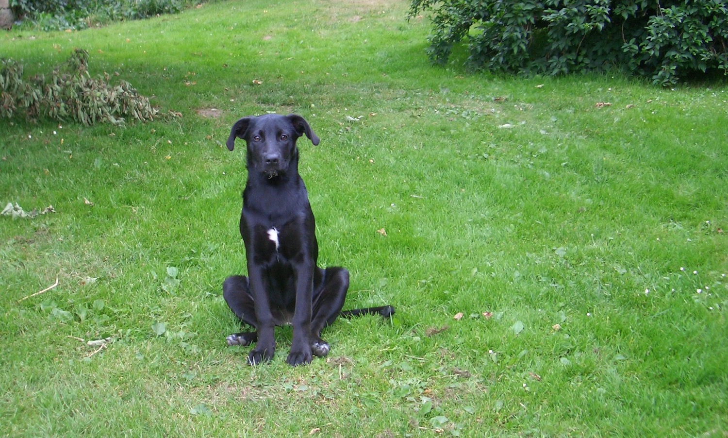
During all this my friend was giving me skeptical looks.

Vanagon – stock tire carrier replacement idea
Posted by albell in syncro, vanagon, vanagon mods on May 10, 2014
I should have spent the time finishing the rear bumper build but over the last two days I grabbed a couple of hours alone in the shop and tried out an idea.
When I do get the rear tire carrier built, and I am almost there, I will be moving the spare from the front to the back. I guess I didn’t need to tell you that. The free space up front, what to use it for? Well I have that big assed AGM battery that I’m struggling to find a spot for. Why not put it up front? There are arguments pro and con for this idea, but I decided to have a go, at least a start.
There were three kinds of stock spare tire carriers. The tray type, in two sizes, and a cage type that you don’t see that often here in North America. Here’s a pic.

I like that carrier and i like Tigerbus’s take on it.

I can’t make anything as nice as that, but here goes with my attempt.
I’m using aluminum scraps again. Schedule 40 1 1/4″ 6061 pipe (OD about 1.66″, wall thickness 0.140″), some Shmoo shaped 1/2″ 6061 plate that were left overs from a water jet cut, a bit of 3/8″ plate that was cut out of a boat hull, and some 1″ x 2″ box section 6061.
The Shmoos were welded onto the ends of the pipe, attachment points to match up with the hinges on the van spore tire tray.

And at the other end the pipes notched and welded to the box section at a bit of an angle so it fits up against the back of the bumper where the stock tire tray bolts up.

Trial fitting.

More or less fits.
The rather skanky bit of hull.
Yeah, the other side is painted. That made welding a bit of a chore.

Tacked in place.

I did a full weld-out on the unpainted side. I welded it hard and fast so that the paint didn’t fume too much. I should have used the wire feed welder instead of TIG.

Now at the front, I will be adding more stuff there, coming up in front of the bumper similar to the Tigerbus version. Im also going to add some side pieces that will angle up to meet the frame rails on the van. These bits will add side protection and will be additional points of attachment to the van. I do worry about the thing falling off with that big battery.
Vanagon – bridging ladder
it’s been a while since i posted anything, busy at work and at home. I have some Vanagon stuff to post and I’ll get on it as I can.
This post is about a bit of fiberglas grating I picked up to use as a bridging ladder. I’ve been looking for off cuts of the is material for quite a while now and last week I finally found some. The source is interesting but I really can’t say where. This kind of bridging ladder is commonly used in the UK and Europe but I don’t see it being used much over here in Canada. Here is a link to a UK source.
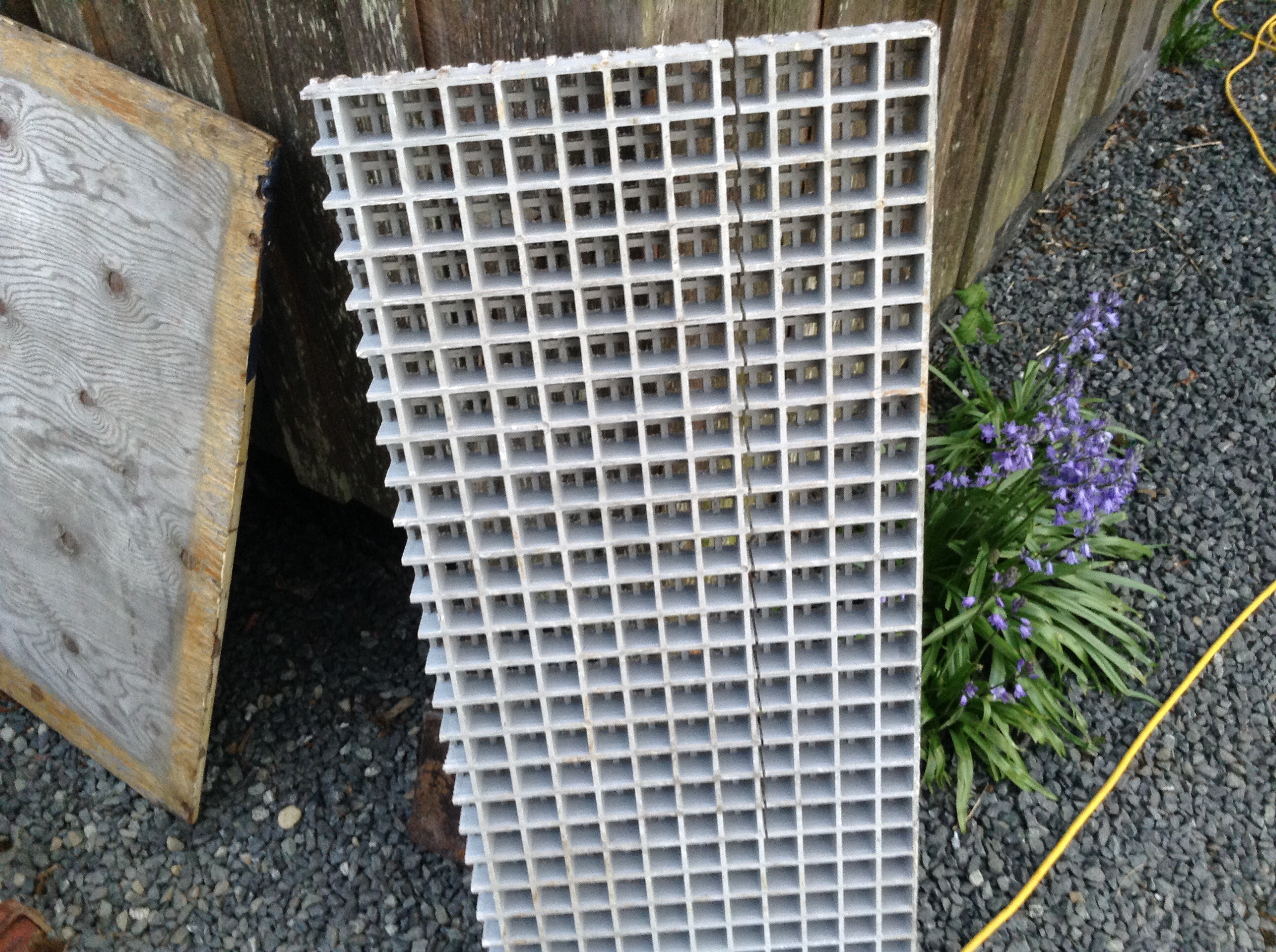
What I found was slightly different as what you see on that link, it has extra webbing on one surface and a very coarse anti slip grit embedded on same surface. Also it had been partially cut, annoyingly so as it screwed up a neat division into two long usable pieces. And it is about 38mm thick, major grid size is about 1 1/4″ square. You have to love the mix of measurements.
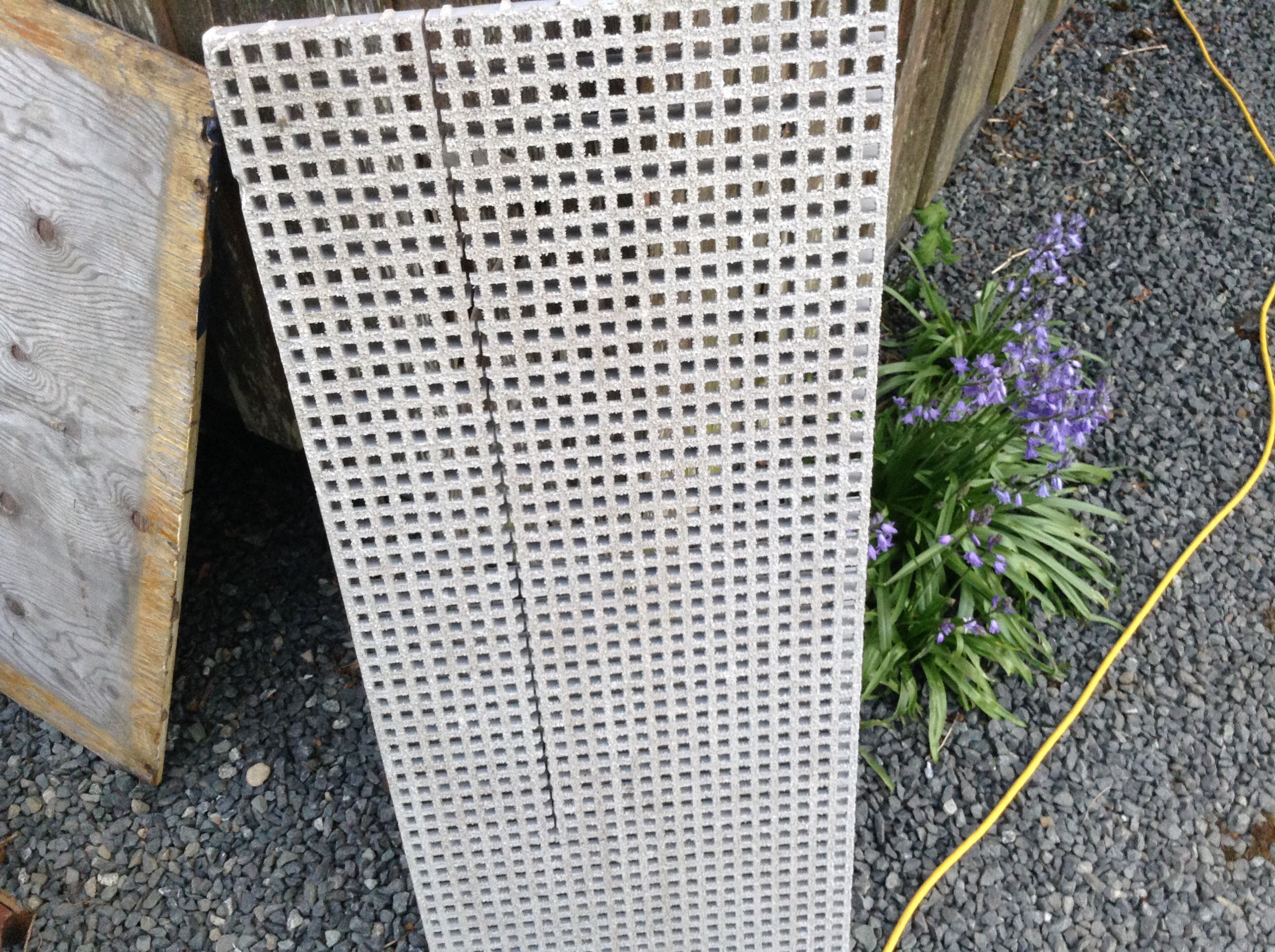
I cut it it to get one good strip and gave it a test. You can see how it bends but doesn’t break.
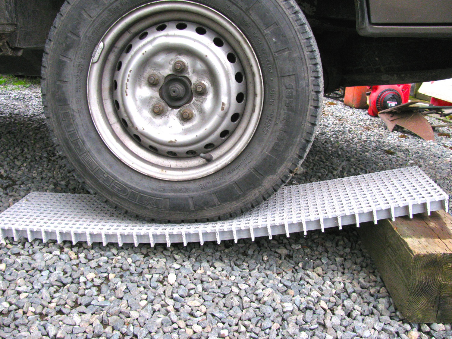

They left over strip, still with the partial cut in it, was strong enough to make a ramp.

And the un cut section supports well.
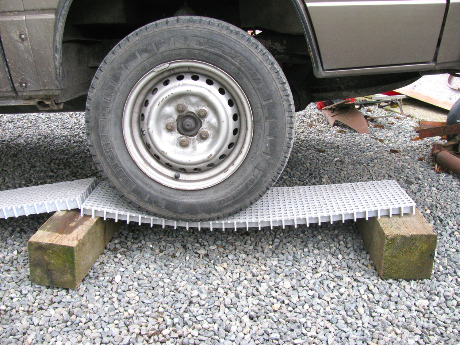
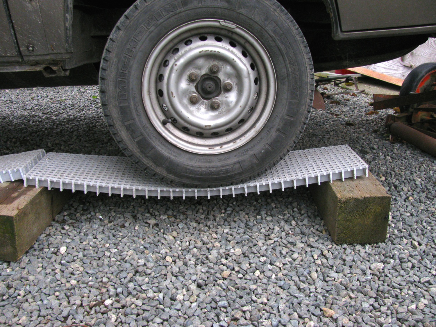
I have to explain why i want something like this. On logging road spurs you often find water drainage trenches cut across the narrow road. Seems to be the norm nowadays instead of installing a culvert. The trenches can be deep and steep sloped, either by design or by the drainage water eroding the sides. Sometimes the shape of the trench makes a perfect tank, I mean, Vanagon trap. You only need a little help to get across and I think even one bridging ladder will do.
Vanagon – yet another bumper build update
Posted by albell in syncro, vanagon, vanagon mods on April 1, 2014
I got something done today on this never ending project. I bought some C channel steel (1″x2″, 3/16″ thick) to replace the stock bumper mounts. I cut them long enough so a third bolt can be used to secure, just like the stock VW trailer hitch set up, and just like the RMW bumper system. With those channels rough cut and inserted I was able to offer up the bumper to the van, fitting it to pretty well its final position.

I attached the unfinished swing away tire carrier.

And popped on a spare. I was worried that I had screwed up my measurements and the tire would cover part of the left rear light. But It clears it ok.

The bumper was not attached to the rails so it did tilt back a little. The tire carrier upright should be closer to the hatch.

And swung out, the tire clears the van.

ATA – Beaver crossing
Posted by albell in aircraft, around the airport on April 1, 2014
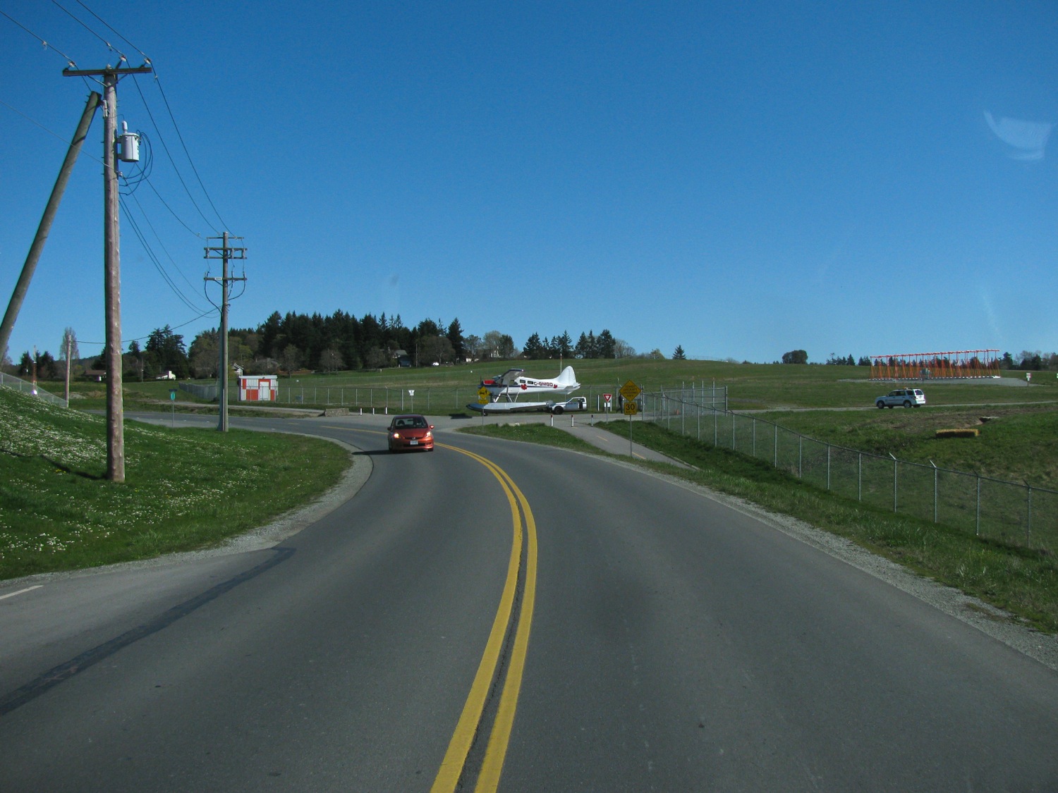
Been quite some times since I have posted a plane pic here. I dunno why. But I couldn’t help but get one while driving near my house today. Beaver about to cross the road.

Taiwanese copy of a Kurt vise
Posted by albell in metal working, metalworking on April 1, 2014
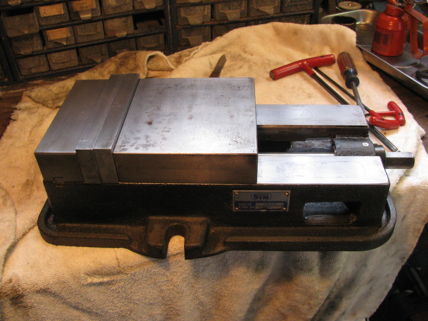
An old rusty bit of hardware was plopped in my lap the other day. It’s a STM CH-6 milling vise. Pretty well a direct copy of a Kurt. I didn’t think to take pictures of the state it was in when i got it, but did get some pics of the guts of the beast.
The claim to fame of the Kurt vide is the little gizmo in the sliding jaw that causes that jaw to push down when tightened on the workpiece. Kurt calls this “Anglok”. Here is a link to a pdf file of a Kurt vide that shows the Anglok feature.
Now the STM I was cleaning up does not exactly copy the Kurt, but does have the “Anglok” feature. Ok, now onto the pics…
The underside, yes it is a big bugger.

Yeah, I know most of you don’t have a clue what this next pic is showing. The underside of the sliding jaw showing the depression where the hemispherical part fits. This is the key of the “Anglok” idea.
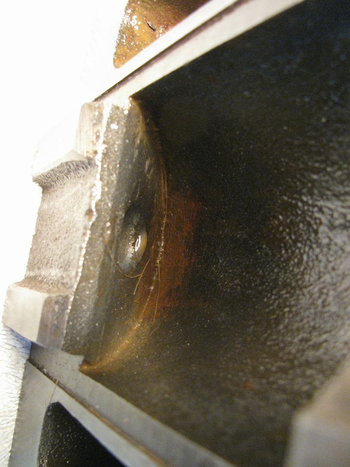
Aforementioned hemisphere.

Movable jaw removed. Look at the casting at the end of the screw, you can kinda imagine it has an angled face on the underside. That angled face presses on the flat side of the hemisphere. Also note the rust etching on the ways, where the jaw had been parked. The vide was sitting outside, getting oh so rusty.
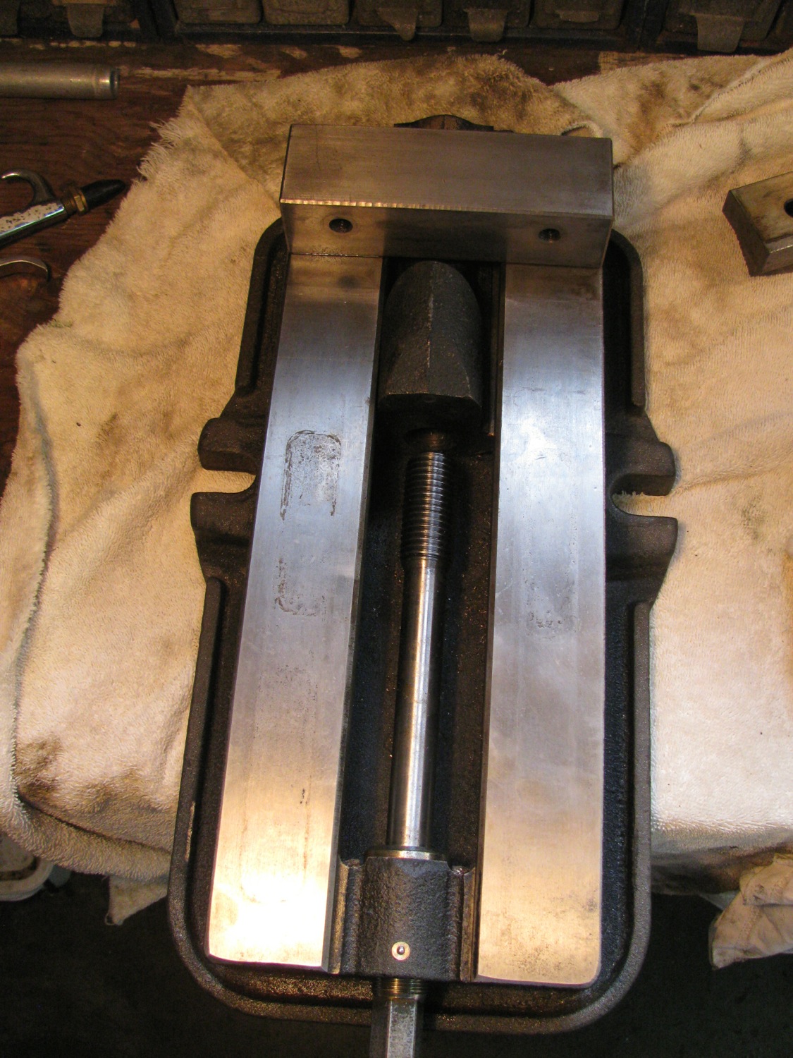
At the handle end of the screw there is a thrust bearing.

Oh this pic shows an allen key in the set screw that adjusts the free play on the “Anglok” system.
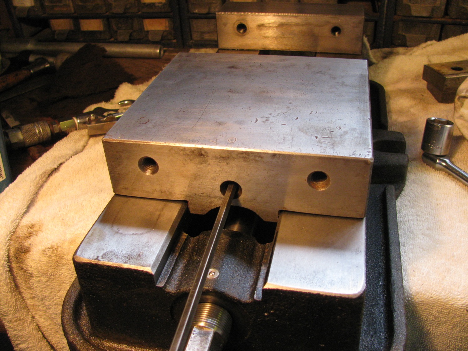
All cleaned up. apart from the rust, there was a lot of congealed cutting fluid and chips to get rid off. I was surprised that hit cleaned up as nicely as it did. It works smoothly, nice vise.
Vanagon – jury rigged fix for deceased cat
Posted by albell in syncro specific repairs, vanagon, vanagon mods on March 28, 2014
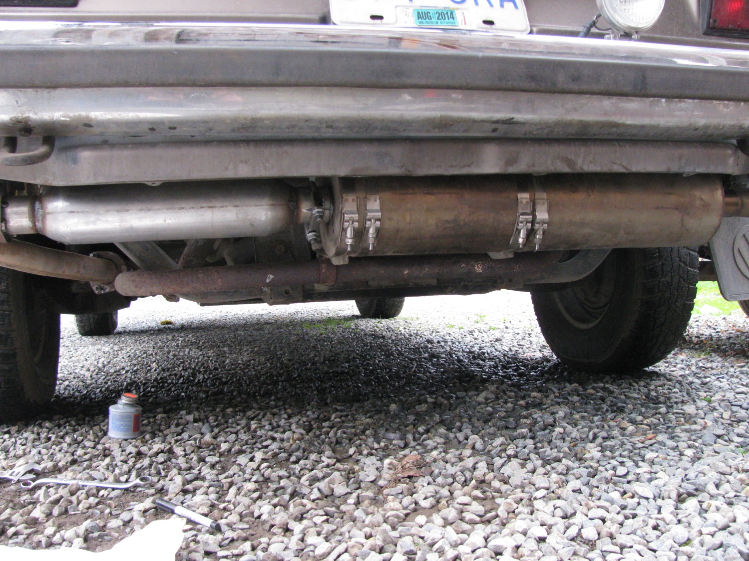
This post might get me some guff, but please have patience, I will get a new cat. The catalytic converter on my van is old, very old. Recently I’ve suspected it really was a converter in name only. I took it off today and it was empty. All the rare earth metals and ceramic had blown out through my stainless muffler. Ok, so now what? I had the shell in my hands and I decided to do a little experiment before i hunted up a new cat.
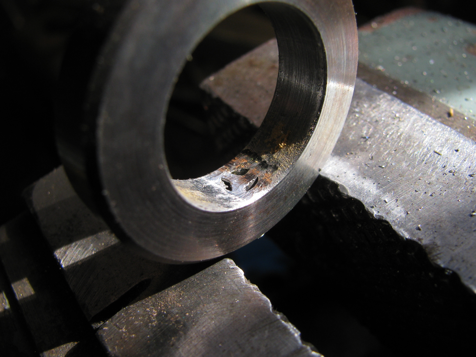
I had this resonator muffler thingy hanging around the mess I call a workshop. It is a little longer than the cat but I thought I could slap it in place and see how it effects the sound of the exhaust. Ok, here goes..
The resonator, 2″ outlet/inlet. I scrounged a 3 bolt flange and cleaned it up on the lathe. Bored it out a tad so it would fit on the pipe.

You see? Pipe set into the flange.

And positioned not quite all the way through.

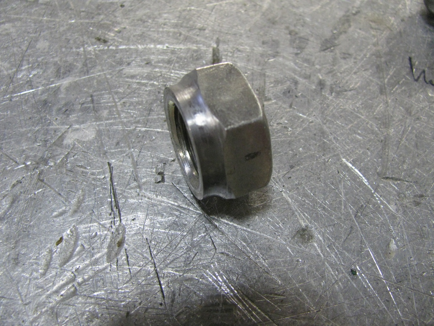
While I was at the lathe I necked down a nut to act as a threaded bung for the O2 sensor. Man, I just can’t recall the size of that nut right now.
Tacked the flange to the pipe.

Then a mostly autogenous weld inside.
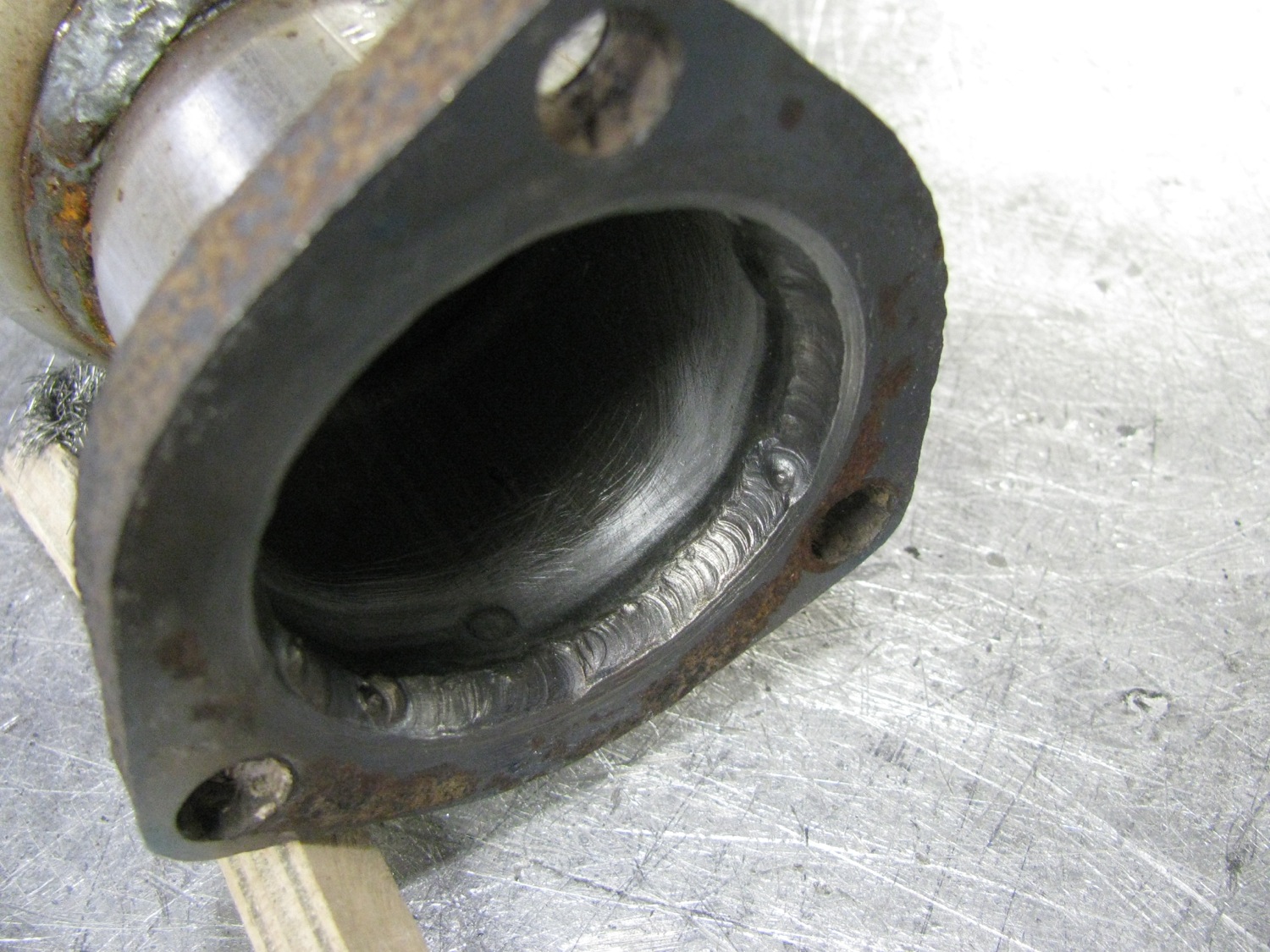
If you squint you could imagine that hole was roundish.

Necked down nut pushed in hole.

And a bit of a heavy handed weld.

Two slits on the other end (tubing fits over the tubing inlet of the muffler. The slits will let the muffler clamp squeeze the assembly tight)

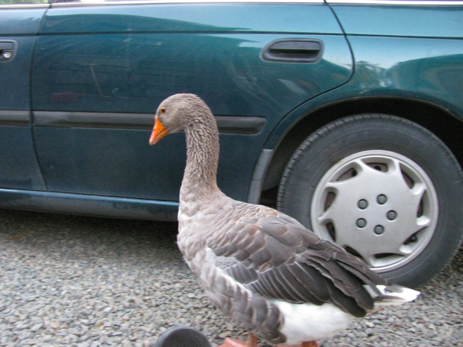
During installation my new lover was pestering me. For the last few weeks this goose has decided I am something special. I really don’t know what is going on with her.

I had to slide the muffler over a bit to get the resonator installed. It does look a bit funny, I admit. And did it change the exhaust sound? Yes it did, it is a bit quieter, with a hint of raspy with quick throttle off.
Vanagon – totally superfluous lantern holder
Posted by albell in vanagon, vanagon mods on March 24, 2014
This is the result of Felder Enterprises announcing a lantern holder made using a Bus Depot awning gutter clamp. I can’t let FE get ahead so before I got down to paying work I made my own version. It is based on a design I’ve seen on the web that uses PVC tubing and a PVC “T”. But I had some aluminum stock so I used that.
I milled a slot at one end to hold the lantern bail.

And a slot to go over the rain gutter.

And a bit of paint protection.

On the van.
And surprise, it clears the sliding door.

I have no pressing need for a lantern holder, I guess i was just in one of those moods this morning.
Addendum, 28/03/2014
Well it seems that i didn’t get the itch scratched, i made another hanger. This time from some scrap thin walled stainless tubing. Part of it was the end of a roll, so it had a little bend to it. I thought that might be interesting. I ground the welds out just to make it look a little sleeker. I don’t think it works as well as the aluminum version, the tubing is so thin that the slot that goes over the gutter spreads a little when weight applied to the hanger. But it might be strong enough, we’ll see.

h

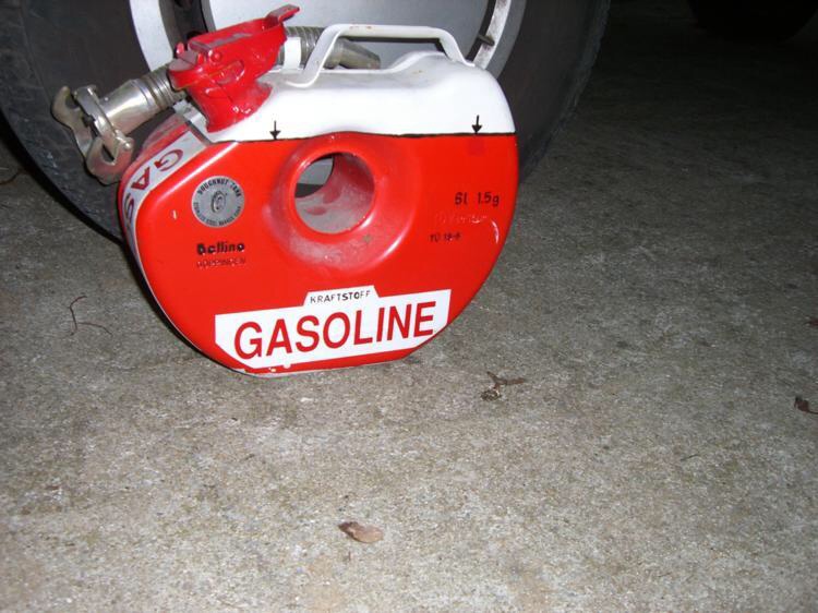
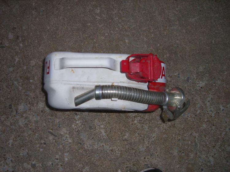
BMW doughnut gas tank
Posted by albell in other cars on March 13, 2014
Fellow vanagon mailing list member John R. owns this tank and wanted to share some pics. Just in case it is not clear, the tank fits into the rim of the spare tire.


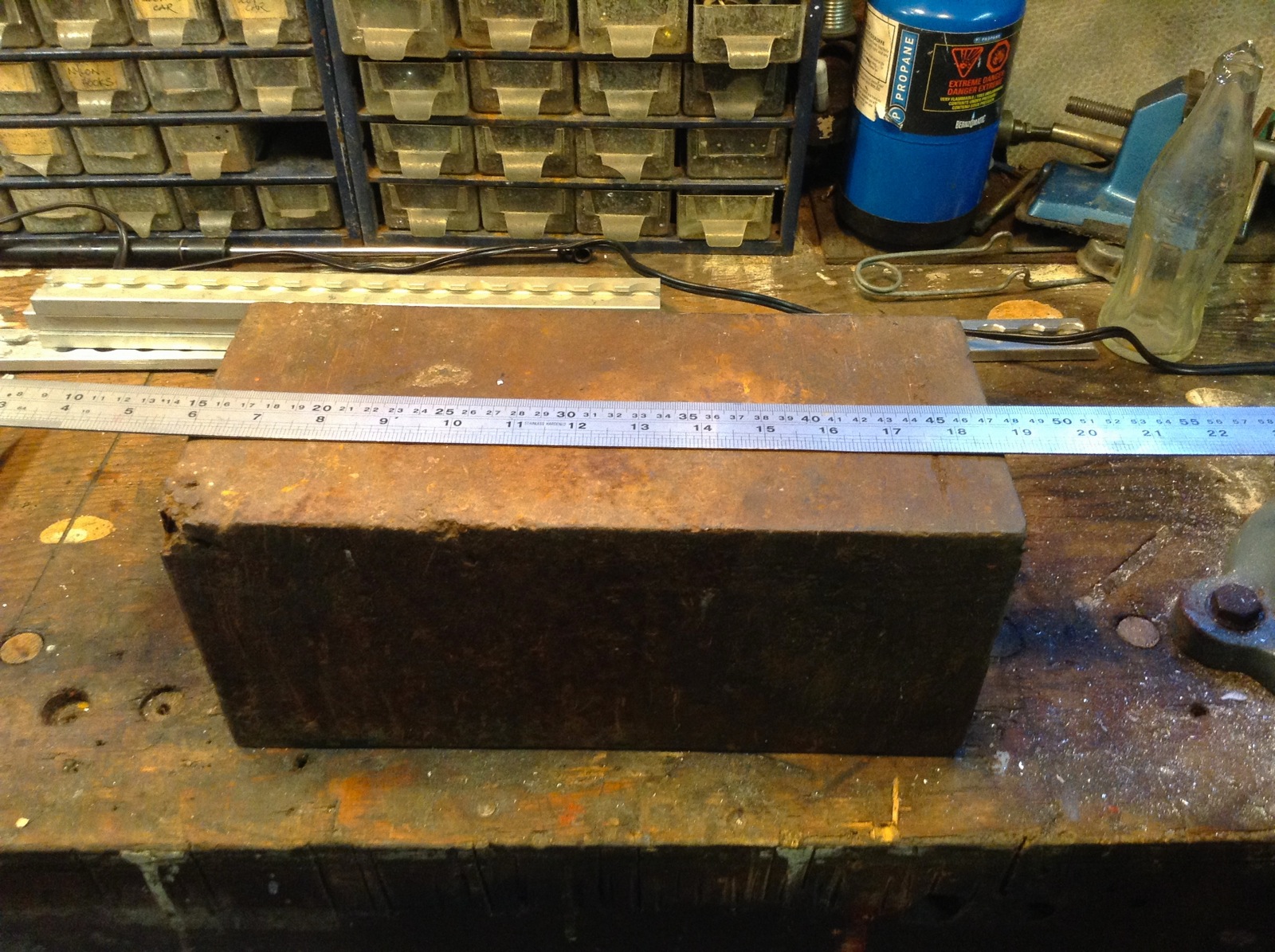
Hunk of iron
Posted by albell in metal working on February 23, 2014
Well I say iron, but it could be steel. Measures 5 1/2″ X 5 1/2″ X 12 3/4″ ( 140 mm X 140 mm X 343 mm).
If it is pure iron then it weighs around ( at 7.87 g/cc) 52.9 kg.
I don’t-know why this hunk o’metal pleases me, but it does. Probably says something about how easily amused I am.
Vanagon – swing away tire carrier – more on the latch
Posted by albell in vanagon, vanagon mods on February 20, 2014
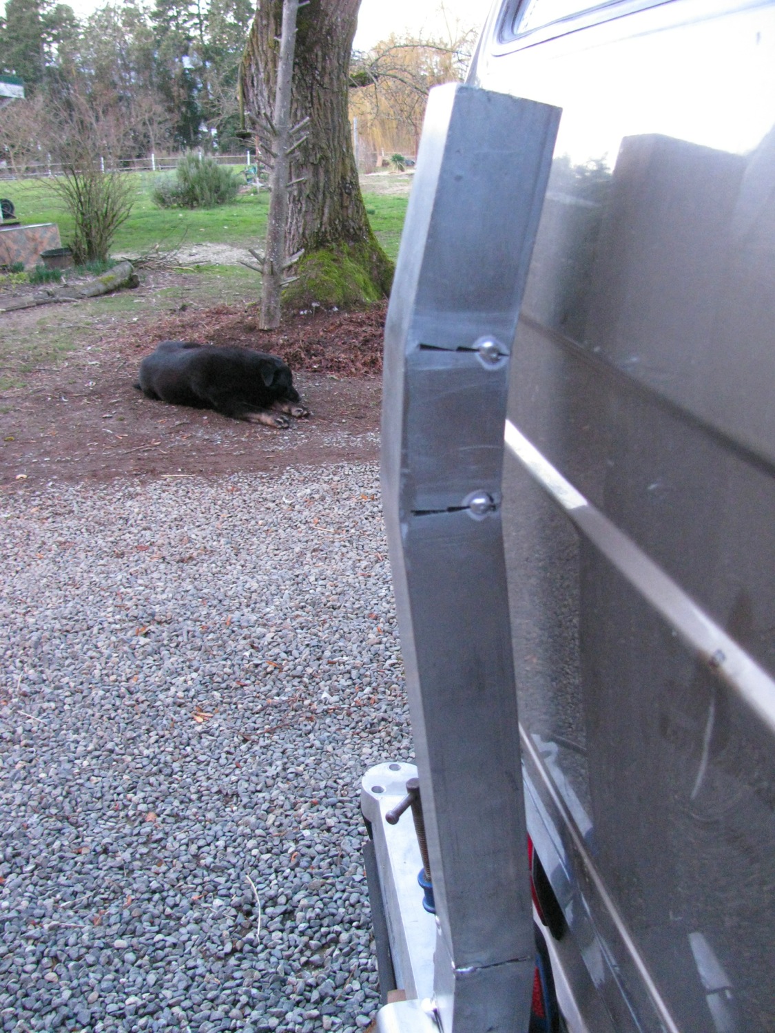
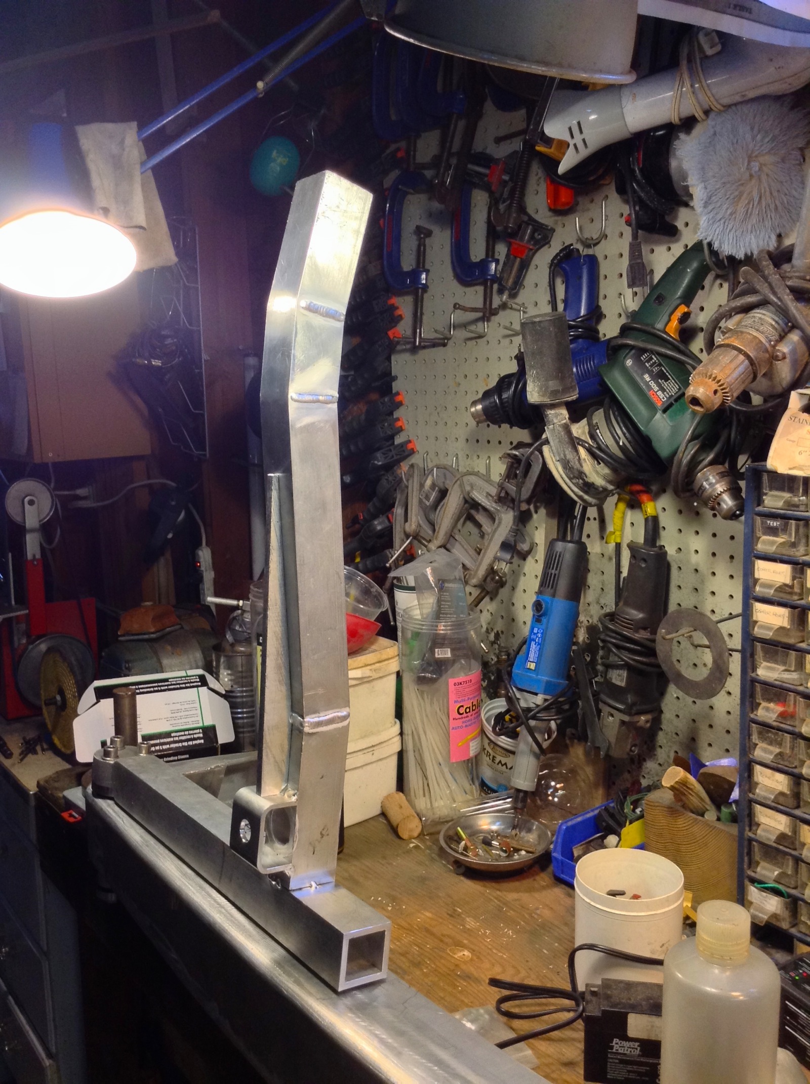
Ok, I know this conical latch idea of mine is flakey but bear with me. I got some things tacked up today to see what was what. First is the upright that will hold the spare tire. In my last post I said how I had to make an adjustment to get the upright close, but not too close, to the back of the van. My solution was to cut and bend the upright to mirror the profile of the rear of the van. Here are some pics with the upright (not fully welded out yet) roughly in place. My swing away arm is just clamped to the stock bumper.
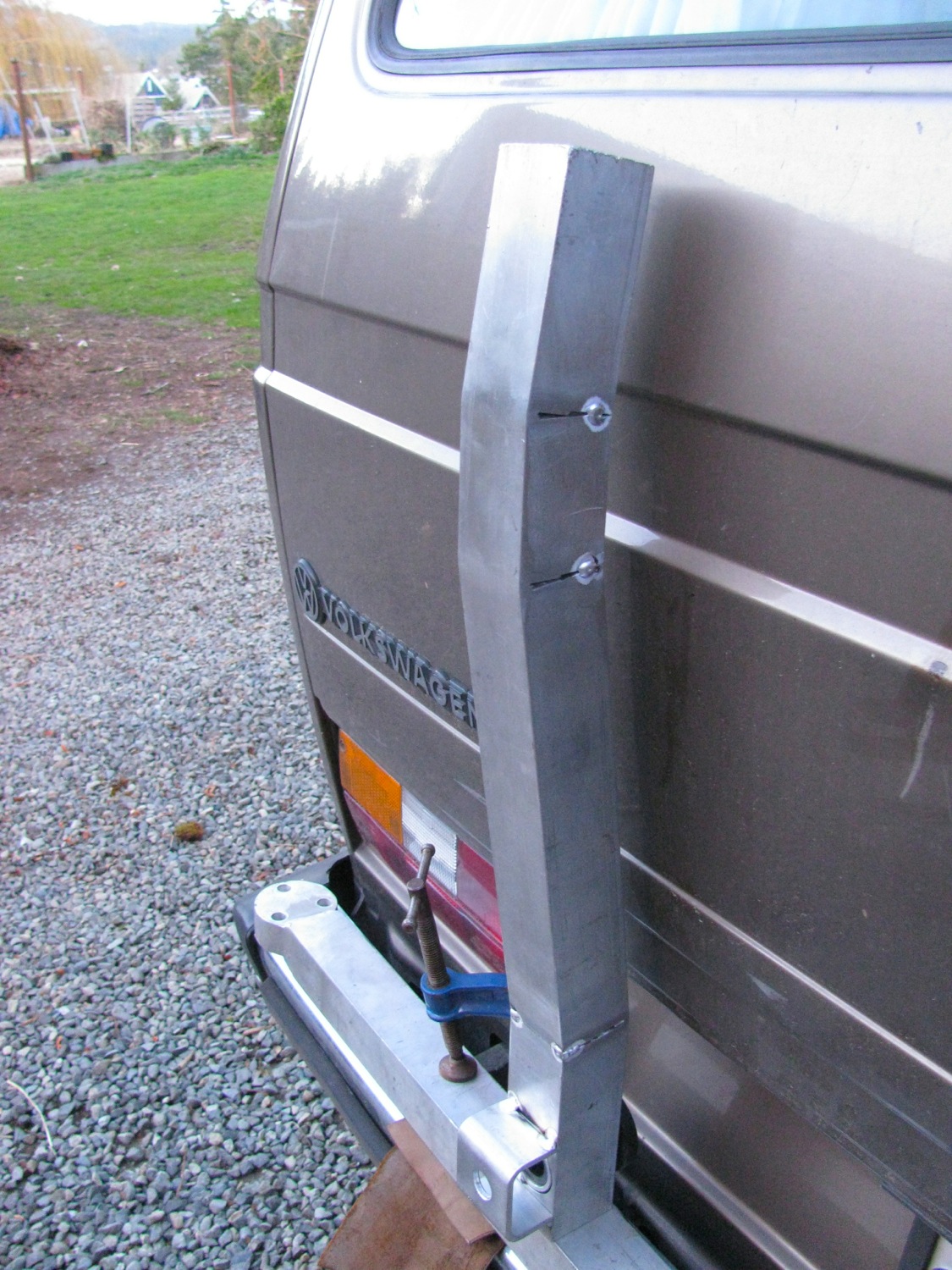
I think this might work.
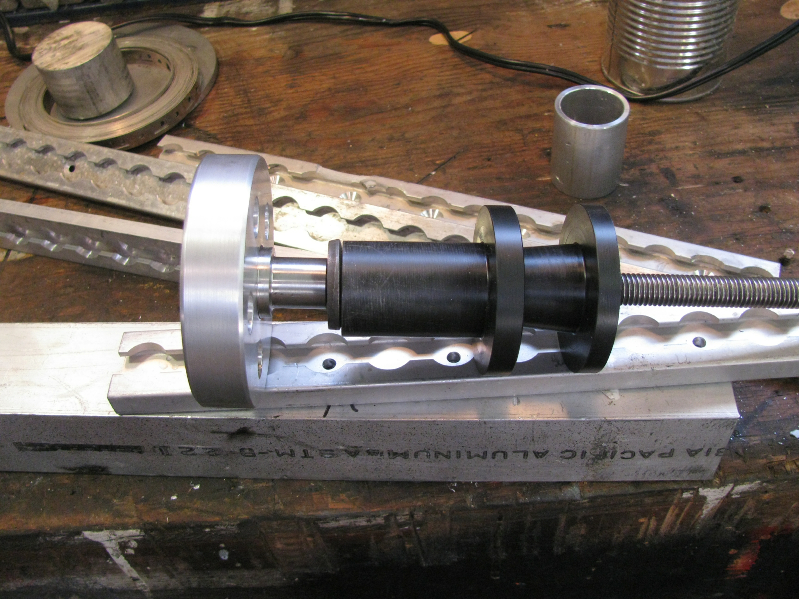
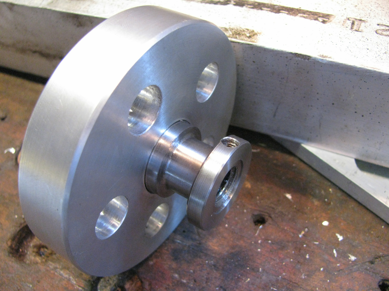
Ok, on to the latch. I tacked welded a bit of U channel onto the upright and I also bored a hole for and tacked in the short section on alluvium tube that you saw in the previous post and that houses the female Delrin part of this cockamamy set up. Here is the latch assembly more or less assembled. But some notes of explanation needed. Of course the threaded rod has not been cut down to size yet, and that metal but you see right against the left most flange represents the back stop I have yet to weld to the bumper. the two flanges meeting (and I think I might slim them down a tad) are the male and female parts in tight congress.. on the right hand side of the box section upright you can just see a trimmed down nut on the threaded rod, the thread rod, then the hand wheel. See the collar in place inside the “cage”? I need to make a set screw for it. The collar does two things, keeps the hand wheel from falling out of the cage when it is unscrewed from the rod, and when the hand wheel is turned to unscrew from the rod the collar pressed against the cage and pushes the upright away from the back stop.
I really am not doing a good job of explaining this. You’ll have to wait for a video or something.

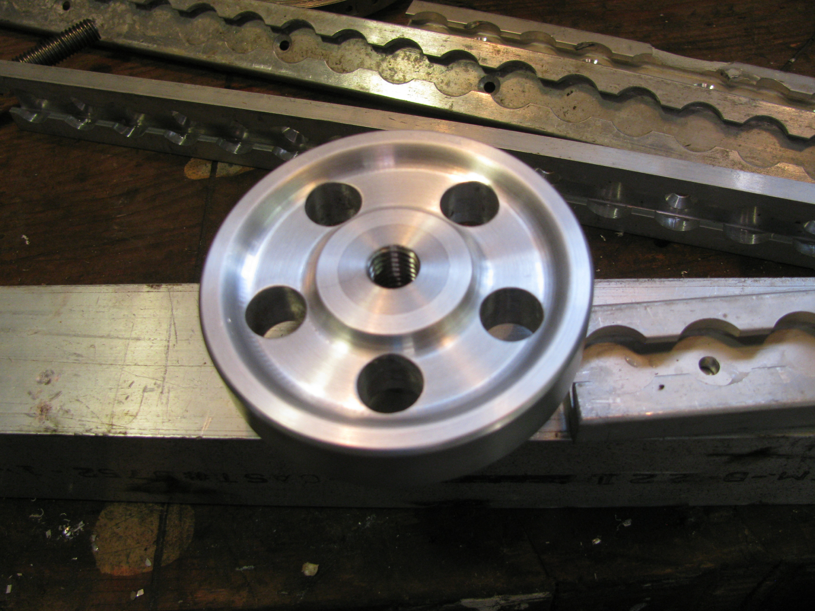
Face on view. Aren’t I a clever fellow making 5 holes in the hand wheel reflecting the five holes in the vanagon wheel? It’s this attention to useless details that distinguishes my crazy ideas from other crazy ideas. 🙂
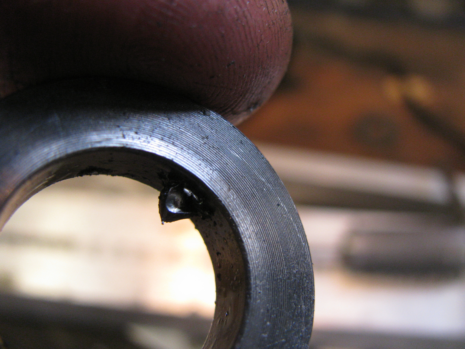
(Here’s something educational. Click on the pic to bring it up in a new tab, then zoom in on the tack weld on the left side of the fully visible seam. You can just make out a hairline crack on the tack. This happens because the heat sink of the thick walled box section tubing draws heat away very quickly from the cooling puddle of the tack weld. To reduce the chance of this happening I should have warmed up the tubing, it was pretty well dead cold. )

Male and female separated. Time for a smoke.

I think I can weld out everything now, and trim down a few of the moving parts.
Update: 21/02/2014.
Dirk over on the IG16 syncro forum expressed some concern that the upright being made of aluminum would waggle back and forth like one of my dog’s tails. Any time a German engineer gives advice it behoves one to listen 🙂 . So today I welded up (not very well, i was rushing) the upright and tacked it to the swing arm, and I cut out a reinforcing piece to weld in (3/8″ thick 6061 stock). I am almost positive now that things will be wedding night stiff when finished.
Vanagon – swing away tire carrier latch – a start
Posted by albell in vanagon, vanagon mods on February 19, 2014
I’ve been amusing myself (!) by attempting to make a latch for the swing away tire carrier that’s going on my aluminum bumper. I have this almost unreasonable desire to make sure the horizontal arm of the carrier is fixed hard against a back stop on the bumper. I know other designs use an over the centre draw latch mechanism, and I am sure they work well. But I got in my head that I wanted to try another approach.
The back stop mentioned will be a sturdy bit of aluminum plate welded vertically to the forward top edge of the bumper. Something like a 4″ X 6″ bit of 3/8″ plate. It will be positioned at a point on the bumper were the end of the swing arm end up when the arm is “closed”. Now imagine a truncated cone projecting horizontally back from that plate that fits into it’s female mate that is in the swing arm. The cone arrangement will, I think, locate and secure the arm to the back stop.
Instead of a draw latch I decided to have a captured screw handle on the swing arm. This screw handle will engage a threaded rod projecting out from the male cone.
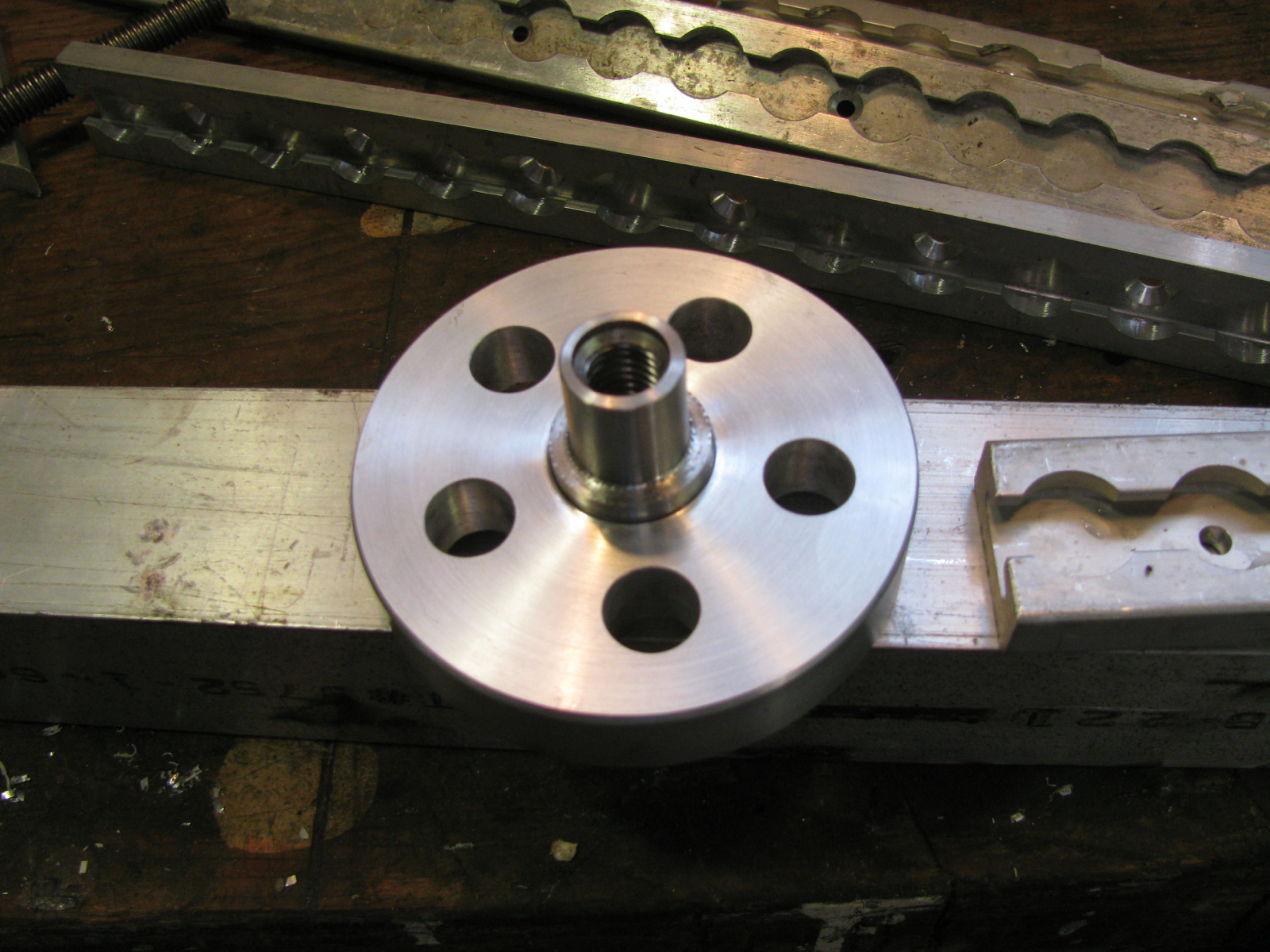
Yeah, it doesn’t seem very clear and I don’t have a sketch of my idea. But here are the parts I have made so far.
From left to right: hand wheel/screw handle, male cone (will be attached to back stop), female cone partially inserted into bit of tubing that will be welded into the swing arm.
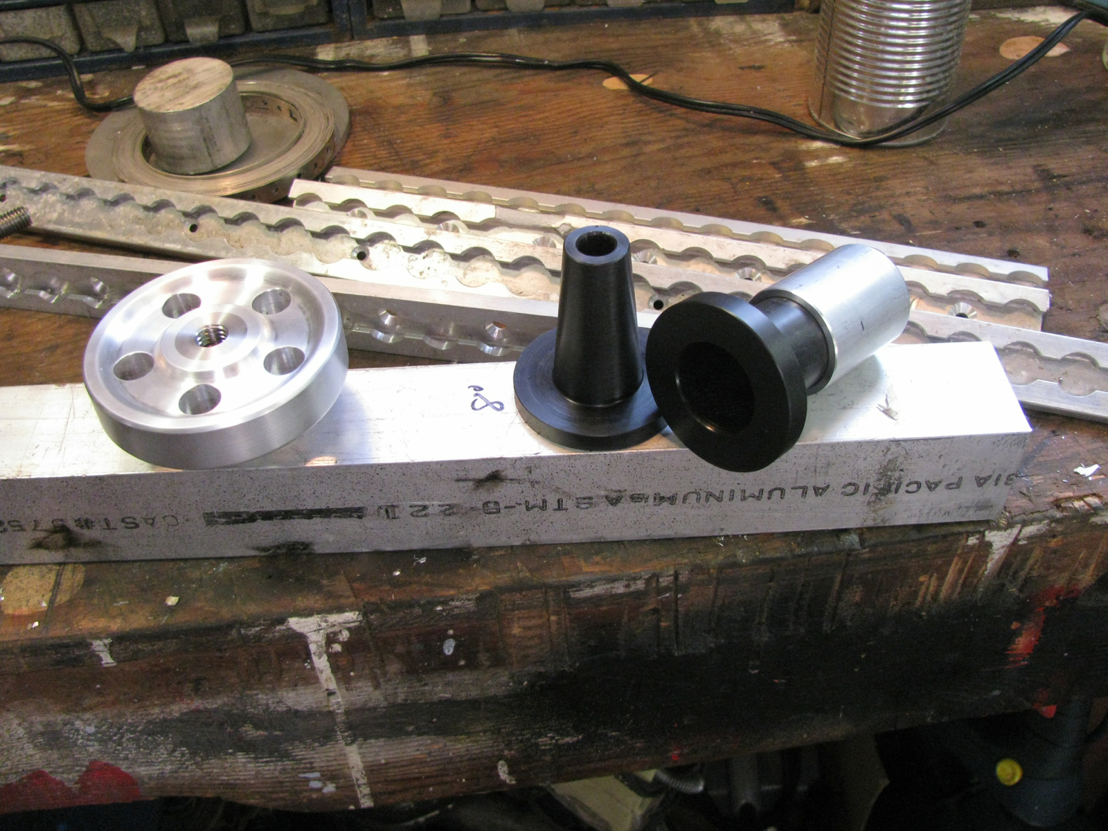
The cone couple. 10 degree included angle, made from Delrin. It is a tight fit into the aluminum tube that will house the female cone. A bit of glue and a couple of countersunk screws on the flange will hold the Delrin in the aluminum.
The hand wheel (going to call it that from now on) is made from scrap aluminum with a centre section of stainless steel pressed in. I mean really pressed in, a shrink fit. I heated the aluminum and drove the stainless into, the somewhat enlarged by heat, hole. Then I fancied it up with a turned recess and some holes. The stainless centre is threaded for 1/2″ NC.
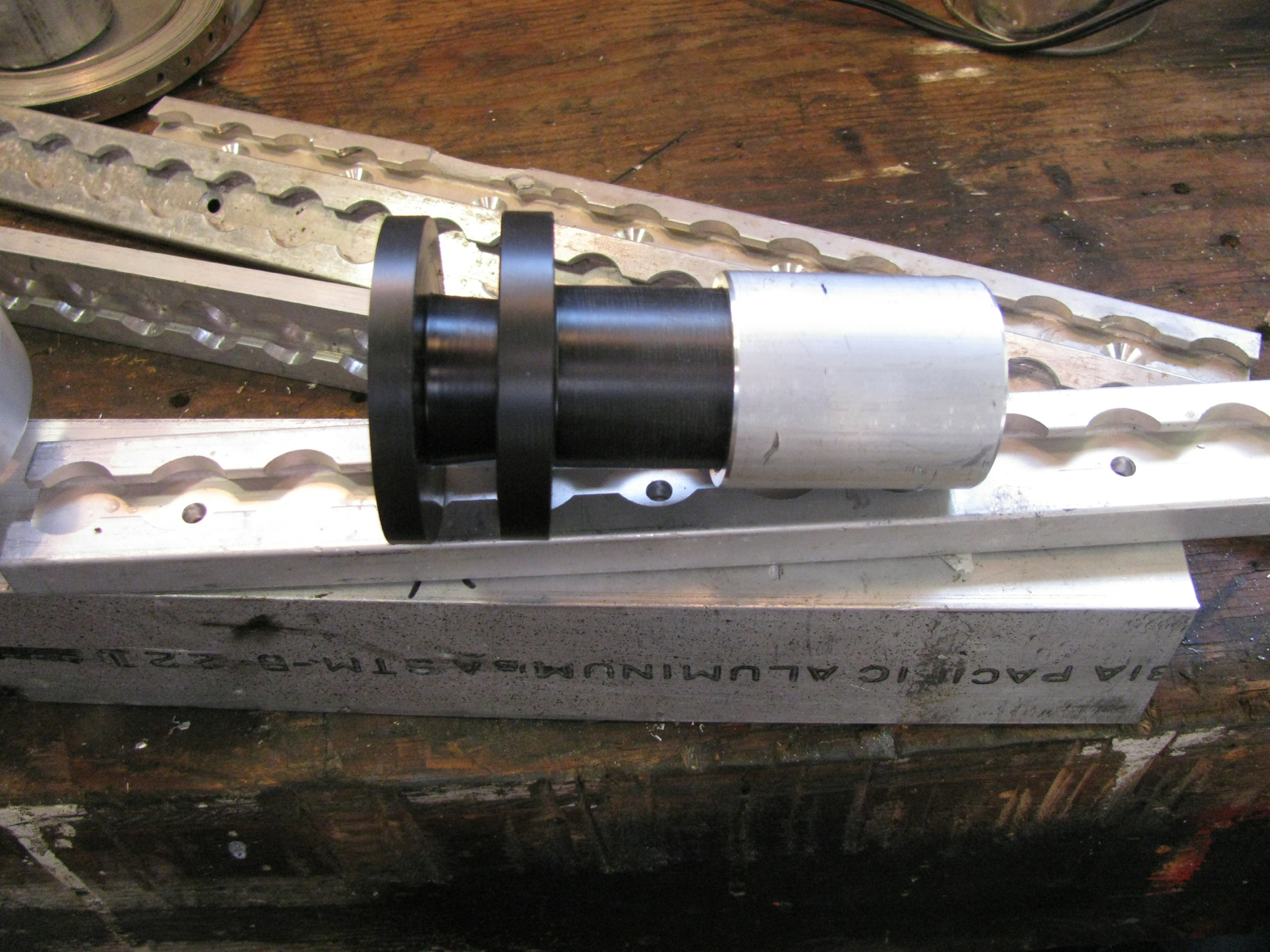
The other side. The narrow section will be inside the “cage” that I have yet to make that will hold the hand wheel to the swing arm.
Arranged in order.
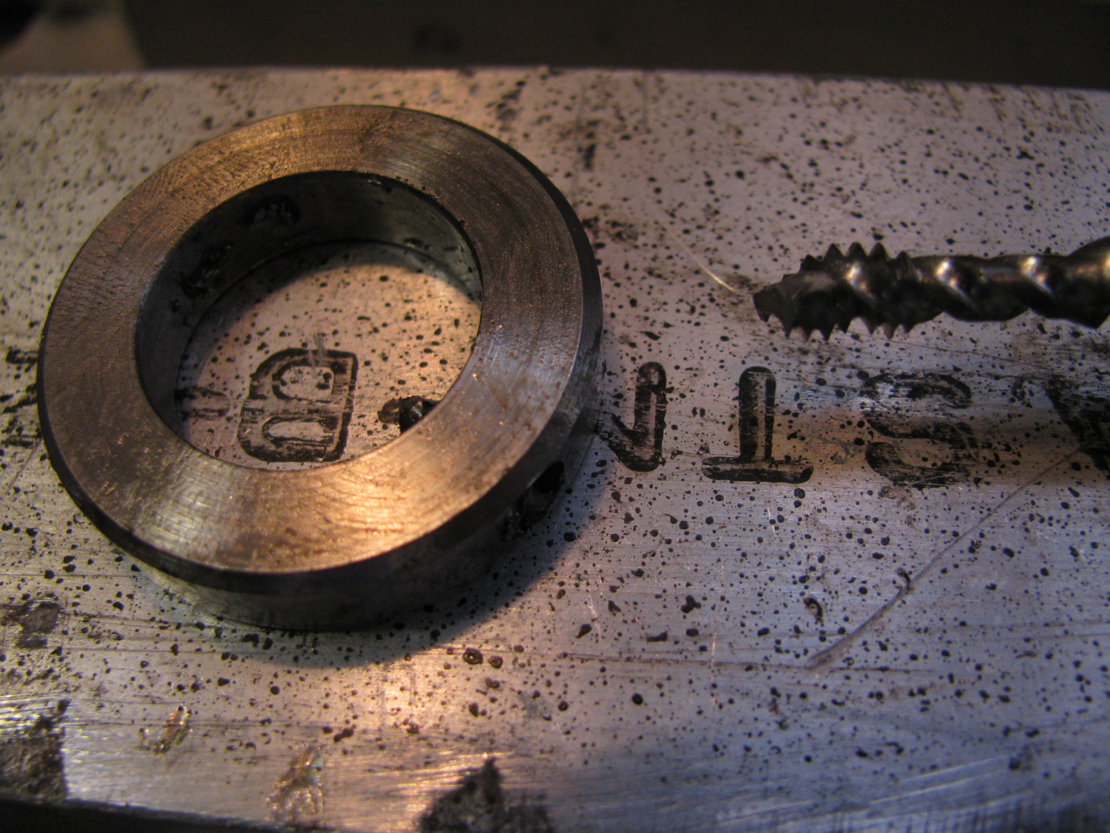
I had to make a collar to put on the narrow portion of the hand wheel to stop it falling out of the cage when unscrewed from the threaded rod. Of course I broke the damned tap when i was threading a set screw hole.
Grr.
I didn’t want to make another collar so i ground down the stuck tap (carbide burr on die grinder) and drilled for another set screw.
I was so pissed that i broke a tap I didn’t get the new hole exactly centred on the collar. Too bad, thats the way it is.
Enough of this for today.
