Prop shaft vibes – maybe solved?
Posted by albell in syncro specific repairs on July 11, 2010
Last week I had some success in reducing prop shaft vibrations. If you read this blog you know I have been chasing this problem up one tree and down the other. One thing to finally clear up before I go on, is the question of the presence or not of a plastic spacer on the front mount of the front diff. I think I can conclude, for sure, that on my diff at least, there is no plastic spacer(s). The hole in the diff mounting ear is too small in diameter to allow the spacers found on the other mounts to fit.

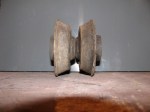
Here is a pic of one rubber mount (they are installed in pairs), a stock plastic spacer, and a home made spacer when I was still thinking my van was missing them.

As is, this still leaves the front diff flange pointing down at 3.7 degrees which is not close to the transmission flange angle of 4.6 degrees. By the book, these angles should be within 0.5 degrees. When I say by the book, I am not referring to the Bentley manual which has no information on this subject. Instead, I get this fact from a drive shaft makers publication, here;
I don’t like the fact that the transmission angles down that much, but I can’t really see how to raise front of trans. easily, and besides , it looks like there is little room above transmission to do this.
Out of frustration more than anything else, I decided to try adding weight to the drive shaft, thinking that perhaps the shaft was out of balance (I had replaced U joints, and who knows, it may have been out of balance before I got the van). I attached a gear clamp 3 ” from the front end of the shaft, right where there is a factory weight. test drive revealed no change. I rotated clamp 90 degrees and, by god, test drive showed a big reduction in vibrations, in fact the vibrations were almost gone.
Next step is to refine position and try additional weight. Local drive line repair shop does not have mandrels to do syncro shafts, but the tech. said he would be willing to make mandrels if supplied with measurements. I may be on to something.
Sway bar drop link refurb.
Posted by albell in metalworking, syncro specific repairs on July 11, 2010
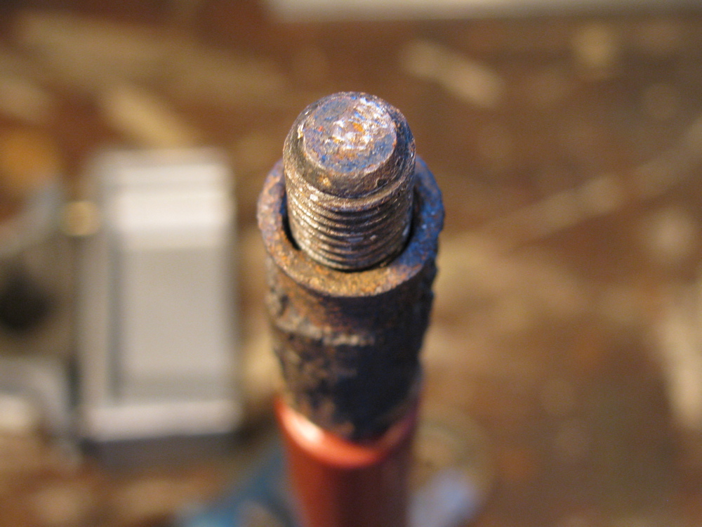
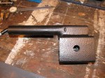
Between watching the Big Game and other things, I made some metal sleeves and convex washers for my sway bar drop links. The sway bar is off the van due to a broken link which I repaired earlier . A broken drop link seems to be a common thing, and its due in part to the steel sleeve inside the rubber bushings trapping water and rusting. This can cause the drop link itself to rust and also when the sleeve rusts out may allow the drop link to move more than it should, stressing it. I fixed the link by facing off the broken stub, then drilling into the link and tapping for a 10 X 1.5 mm bolt. The bolt was screwed in and tack welded. The bolt head was then removed and threaded portion cut to size. The picture shows the repaired link and beside an original. The stainless tubing was just an early try at finding a sleeve.

And just because I thought it a neat idea, I made bushings out of old skate board wheels.

I guess a diagram is needed showing all of the parts…

I needed to make new washers and sleeves (spacer tubes in diagram). The washers are dished and made of steel. The spacer tube is thick walled steel. I am not sure if the washers are still available, and I really wonder if the dishing is needed (allows more “wobble” in the drop link-rubber bushing connection).
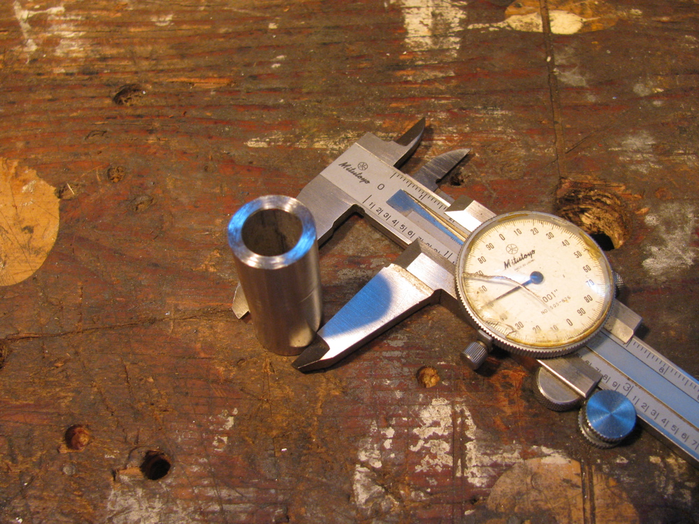
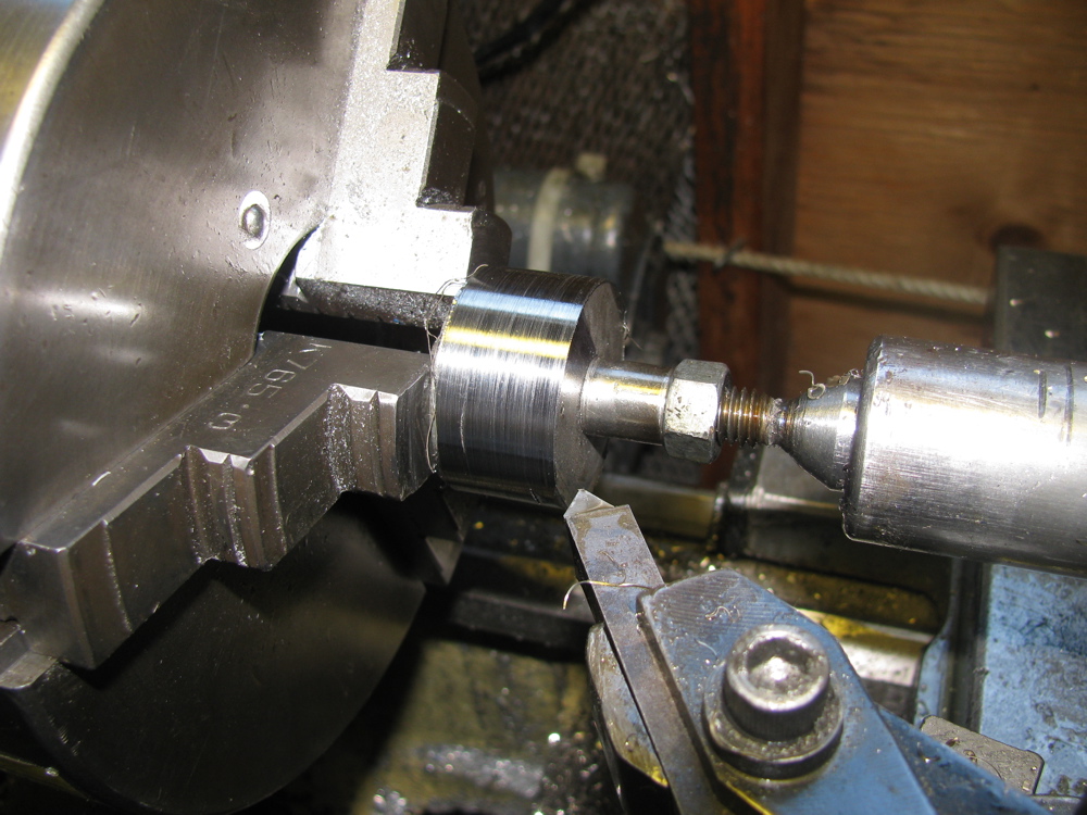
First the sleeves. Some schedule 80 stainless tubing was found at the local Metal Supermarket (I took drop link along for trial fit). I don’t know what the listed size of this stuff is, but a casual measure has it at 0.675″ OD and 0.42″ ID. The tubing was cut into 40 mm lengths (well, that’s what the rusty old stock sleeve was). I nipped out to test fitment in the hole in radius arm and found it was too large in diameter. I had to turn the sleeves down to 0.650″ diameter for an easy fit.
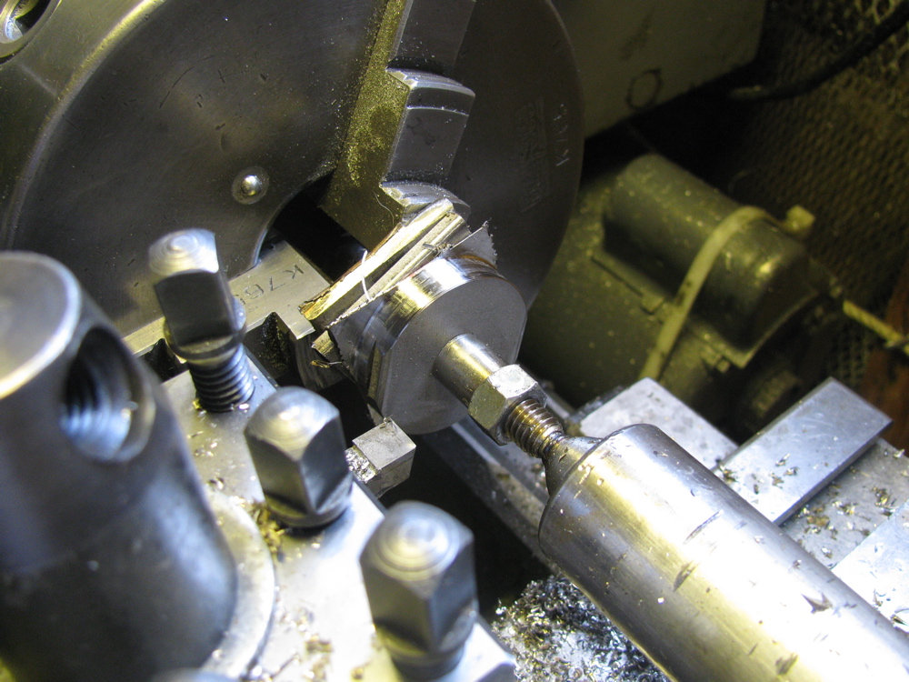
At this point I should mention that I am not a machinist, nor am I a talented amateur, so forgive any bad technique shown and the quality of the finished work. Now onto the washers. I had some stainless bar in the workshop, 1.5″ wide (not quite as wide as the stock washer diameter, you’ll see evidence of that in the pics), 0.187″ thick and I cut it up into rough bits, drilled holes in them and mounted them all on a really dodgy mandrel/spud/spigot/whatever on the lathe. Not the best technique, had to go slow and light to avoid hammering. Of course it would have been better if I had made them into hexagons at least before turning. Anyhow, I made the stack round. Then I mounted them individually on the mandrel and gave them a slight crown. Took a while but I still have my eyesight and digits.
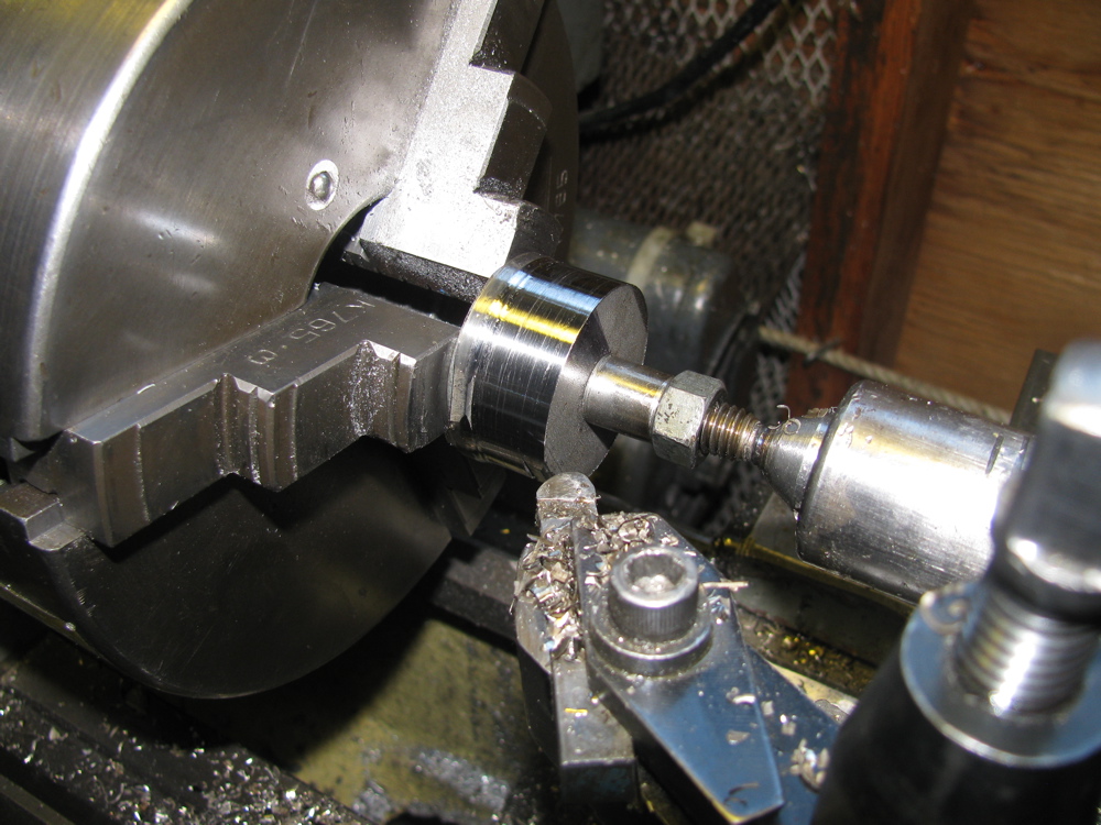
The sturdy new washers are thicker than the old washers and this may be a problem when it comes to installing with the rubber mounts. If needed, I’ll shorten the sleeves by a couple of millimetres or so. Oh a couple of points… I was working on the “other side” with the lathe in reverse when making the washers convex. And you can see evidence in the finished washers that my stock was not quite wide enough, not big deal, just aesthetically crap.
Oh, one more thing, I ground off the little collar seen around hole in washer after I took the pics. The collar was left over from the lathe work. When the washers and sleeve are assembled on the drop link, and the nut is tightened, it all feels pretty solid and strong. I still would like the sleeve to be a snugger fit on the drop link, but probably is just fine as is.
I need to find some rubber bushings now. You can buy stock ones, but criminy, they cost $10 a pop!
Edit: see here for sleeve modification


PS. For images and prices of the “real” parts, check this page from Van Cafe
Syncro Westy – rust treatment and Zetec engine
Posted by albell in syncro, syncro specific repairs on June 29, 2010
Whereas I just poke around the fringes of syncro repair, Ed In Vancouver goes deep with rust repair and a Ford Zetec engine swap. His website is here.
Westy sink p-trap
Posted by albell in vanagon mods on June 27, 2010
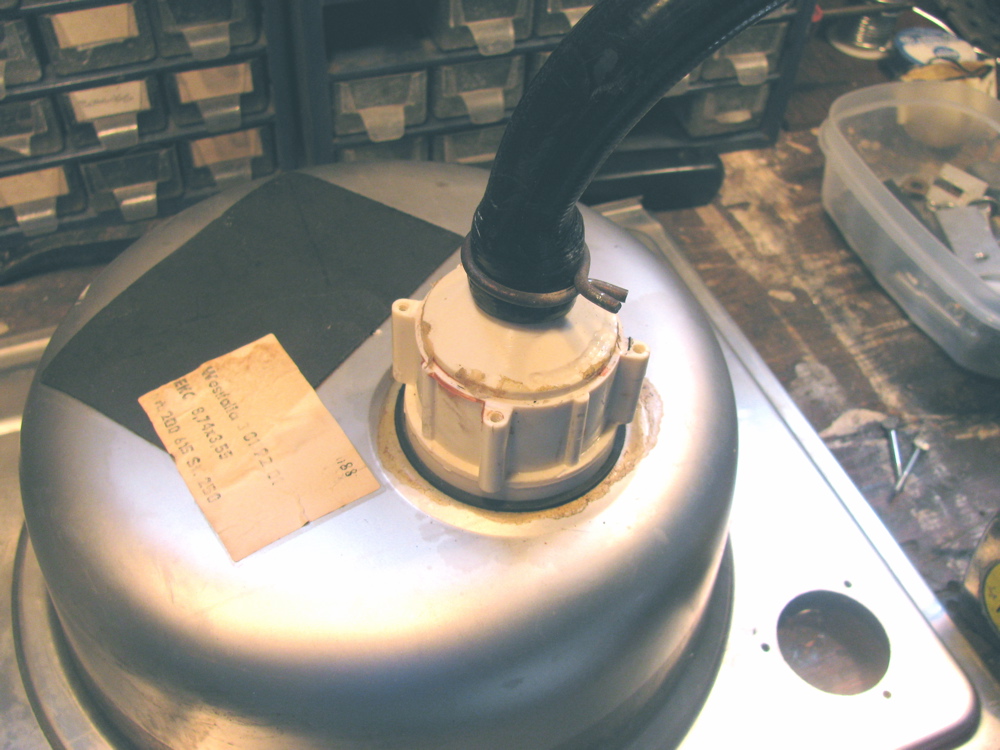
I have the cabinets out of my ’82 westy and while moving the sink/stove top I carelessly broke off the hose barb that connects the sink drain hose. I had replaced that part years ago after i broke it the first time, this time I decided I didn’t need a p-trap on the sink. Why do you need a p-trap there, eh?
I took the trap assembly off (4 screws and a gasket) and I connected the drain hose directly to the sink drain “spout”. That spout is still made of the suspect brittle plastic but try as I might, I could not unscrew the plastic from the stainless sink. Heating the drain hose, which by the way is 28 inches long, with a heat gun allowed me to get the hose over that spout, and secure with spring type hose clamp. Its not a barbed spout, but the hose is on there pretty darn tight.

Home made steering rack bushings
Posted by albell in vanagon mods on June 27, 2010
All my talk about rubber mounts reminded me of this neat home made solution to steering rack movement. I had this posted on my web site, thought I ‘d put a copy here too.
Gary Stearns’ method of how to make your own polyurethane bushing to replace the slopy or worn out stock units.
Gary writes:
“Attached is a bitmap of drawings that I made of these bushings and their installation. The one’s that I started with came from Autozone and were sold as anti-roll bar bushings in a pack of eight.
I was able to get the bushings in and out without removing the rack completely, but it’s not easy. To permit “test fits”, you might want to take the rack out; I’ve done that too and it’s not as difficult as you might think. ”

Front diff. mounts – anomaly
Posted by albell in syncro specific repairs on June 22, 2010
Update: Well I got wrong info, there never was a spacer on front mount. In fact the tabs on the plastic spacer will not fit into mounting hole on the front mount.
I recently posted how I looked at the front diff. mounts and discovered that the foremost one had slightly distorted rubber mounts. What I did not realise was that some syncros have plastic spacers on those mounts too. Mine did not. A quick survey on the syncro and the vanagon mailing lists only returned one other owner (also an ’86 van) that did not have those spacers installed in the front mount. The parts catalogue shows none of the front diff. mounts having spacers, but do list them on the side, and 4 needed (4 would be enough for only the 2 rearmost mounts) You can see at least the rearmost ones with spacers in the Bentley manual. The part number is 251 199 399 , its the same plastic spacer that is found the transmission mount. I decided to try and make a spacer(s) and found a scrap of polyethylene cutting board that was big enough to make a reasonable copy. I just need to make another then install and see what difference it makes in the front diff. flange angle saga.
Here is a diagram of the transmission mount arrangement, the spacer, #9 is the one in question
![]()
And here is a diagram of the front diff. mount arrangement, note absence of spacer in all 3 mounts.

And here is the spacer with my cutting board copy (note flats on sides of my copy, the scrap bit was not quite large enough)

If there is anyone out there interested enough to have a look at their own syncro front diff front mount and report back presence or absence of spacer, I’d be very grateful.
Better measurements of flange angles
Posted by albell in syncro specific repairs on June 20, 2010
Took my time with my revised laser thingy and measured front diff and transmission flange angles. The pictures show the process. Laser on flange, measuring jig on other flange. I added a plumb bob to measuring jig to be sure it was plumb so that any lateral misalignment would show up (you can see the string in the pics). As it turned out there is very little sideways error in flange orientation. I remeasured the flange centre to centre distance as 1820 mm, and the vertical measurements are as follows:
Laser on transmission – dot 103 mm below centre of front diff. flange. This works out to be a 4.6 degree angle on the trans. flange.
Laser on front diff. – dot 83 mm below trans. flange. This works out to be a 3.7 degree angle on the front diff. flange.
The numbers are close to what I measured before, but I feel confident in these measurements. In the pictures the laser dot size seems larger than real life, and in one shot you can see the laser beam itself. The CCD in the camera must be sensitive to the wavelength of the laser.
Note: picture showing measuring stick on front flange and dot around the #8 mark is actually showing an erroneous first try, I had a bit of “schmumf” stuck between laser and flange, second try had dot further down measuring stick, and that is shown in close up pic.


Fastener info and reference
Posted by albell in Uncategorized on June 17, 2010
Nuts and bolts and screws and washers and…
Good reference document, pdf.
fastener manual
Mark III laser thingy
Posted by albell in syncro specific repairs on June 17, 2010
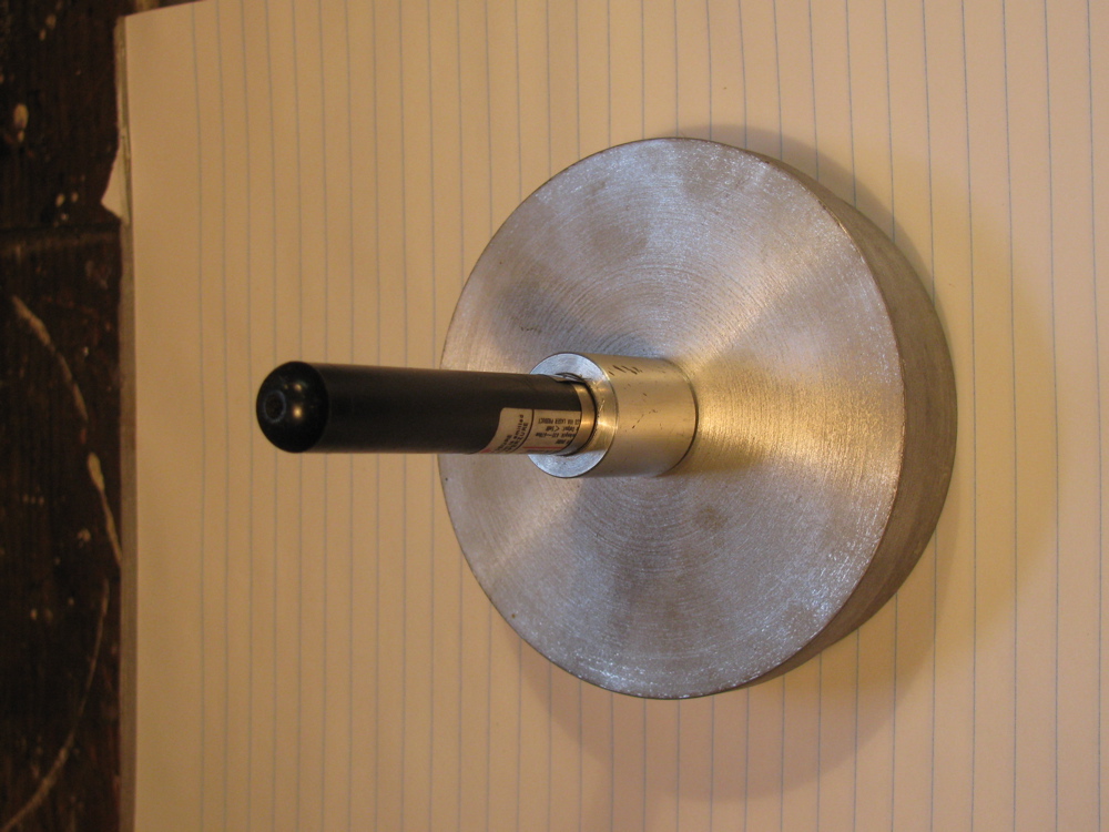
Not being happy with how the laser pointer was held in the jig, I finally did what I should have done all along and that is use the laser’s own mounting bracket. The bit of aluminium angle bolted to the round jig gets clamped by the red bracket’s captured screws (not visible in pic). Now I can adjust the beam so that it is pretty well aligned with centre of jig. Previously the best I could do was a 1 cm circle, over the 1.285 m between flanges, when jig rotated on flange. The thing on the left is the crude reference jig that sticks onto the the flange opposite and shows the laser dot.

Again with the prop shaft
Posted by albell in syncro specific repairs on June 15, 2010
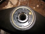
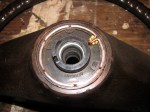
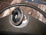
My last posts showed how the transmission flange is pointing down at a steeper angle than the front diff flange. I could not see a way of easily changing the transmission angle so I decided to shift the front diff. I supported the diff with a bottle jack and took off the front carrier and the rubber mount. You can see where the mounts go in the diagram, (No. 6). Looking at the mounts, I could see the lower mount was squished a bit.


So I swapped the thicker, or less collapsed top mount with the lower mount, and I added a couple of washers for good measure to help lift the front of the diff. so that the rear, where the flange is, would point down more.
I did a quick measurement with the Beall Angle Box, and the flanges were within half a degree of each other. My laser thingy showed that the angle had indeed changed, calculated out at approx. 0.65 degree difference…but I am not confident in my measurements. The electronic angle finder is sensitive to how it is placed on the flange and the laser pointer is not perfectly fitted at 90 degrees to the base so that it scribes a 1 cm circle when rotated. I have to refine my methods, but its close enough for the time being.
So I put the drive shaft in and took the van for a drive…. still a slight vibration at 50 kph (mind you, it is less than before). I left the bolts on the 2 rear most rubber mounts of the front diff. loose, wondering if the diff will find its happy spot during driving. No such luck. Will try again but with yoke bolts loose. Next “major” step is to go over lateral alignment.
prop shaft alignment again
Posted by albell in syncro specific repairs on May 24, 2010
Did another quick check on the transmission and front diff. flange angles, this time with my little “Beall Tilt Box” electronic angle finder.

Accounting for the the angle the van was sitting at (approx. 0.25 degrees) I measure a downward angle at the transmission flange of 4.90 degrees and at the front diff. flange I measured a downward angle of 2.50 degrees.
This is pretty close to the quick laser measurement (and subsequent trig calc. ) of 2.45 degrees and 4.45 degrees I did yesterday.
Time now to measure it with more care, using both methods, and then to see if I can adjust either the transmission or the front diff. angles so that they are the same.
God this blog must seem like the most boring place on earth… what an anorak I am turning into.
prop shaft alignment quick test
Posted by albell in syncro, syncro specific repairs on May 23, 2010
I had time today to do a quick check of the alignment of my prop shaft, or rather where the prop shaft goes, as I have it out right now…
I have to reiterate, this was a quick test, approximate measurements only. I attached my laser alignment jig to, in turn, the transmission output flange, then the front diff. input flange. Each time I measured down from the centre of the opposite flange to where the laser dot was. I also measured the distance between the centres of both flanges.
I did not measure any lateral alignment this go round.
What I found was the front diff was pointing down at a lesser angle then the rear transmission, 2.45 degrees vs 4.45 degrees. Ideally the angles should be equal and less than 4 degrees (but not zero degrees).
Here is a diagram of my results:

If you slept through trig, what you need to know is the TOA part of SOHCAHTOA. TOA means tangent = opposite over adjacent. For example in diagram above, for transmission flange, the tangent of the angle is 100/1285 -> 4.45 degrees. Just do the 100/1285 bit on your calculator then hit the tan-1 button.
Here is a diagram of how U-joints can be oriented:

You can see how my syncro is in the “W” bend form, but the 2 angles are not equal. The angles must be equal, or damn close, to eliminate vibrations. This means I have to adjust the angle that the front diff. sits by shimming the front mount.
ATZ 87 (1985) 9
German article from Automobiletechnische Zetischrift introducing the Vanagon syncro. Technical details etc., pdf 860 KB.
Driveshaft alignment tool
Posted by albell in syncro specific repairs on May 18, 2010
Mark II of my laser alignment tool for driveshaft, more to come if I get off my duff and make a registering strip to show where laser dot lands. Inspired by Herman’s work (see blog role, Herman’s Syncro Project).

Ornament
Gets the seal of approval from Jake

Headlight on warning chime mod.
Posted by albell in vanagon mods on May 15, 2010
Just for a lark, I thought I’d try and repurpose the seatbelt/key in ignition warning chime to make it work as “lights left on’ chime.
Funny thing is my van does not have a complete seat belt warning/key left in ignition circuit:
-it does not have a switch on drivers side seat belt latch for seat belt warning light
-warning light unit only has handbrake light and logo, seat belt space blank
-warning light unit does not have wire into connector for seat belt switch (yellow/red)
-door/seat belt warning relay missing
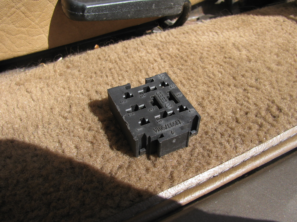
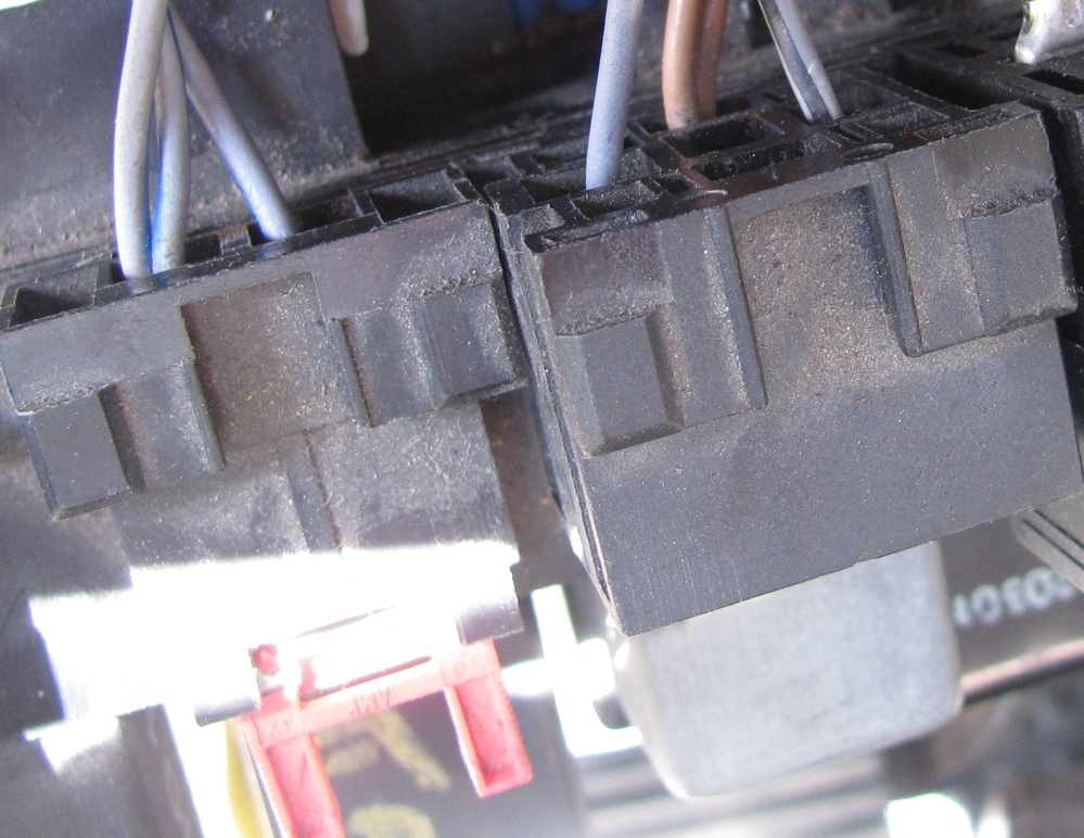
-relay socket on top of fuse panel), has some wires to it, but not all. Missing black wire from fuse S18. only one grey wire from door switch the missing grey is for seat belt switch. Missing grey/red wire that is also part of seat belt switch.
So I thought I would use that incomplete socket to make a “lights left on chime” circuit. Turn out it is easier just to take another socket and slip it onto the relay panel, less fussing with pulling wires out of the relay socket, which is a bit of a pain.
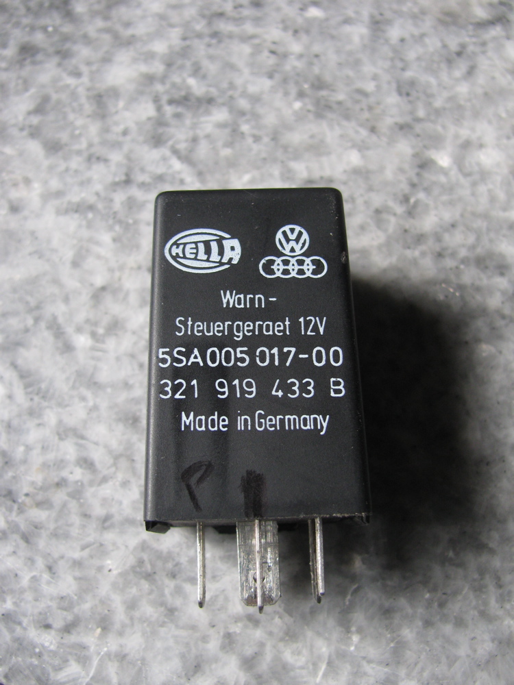
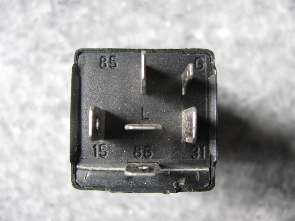
Anyway, this is what I did… I had a 99 chiming relay, the “do-do-do, do-do-do” annoying tune, a spare socket, and a short length of 14 gauge wire with female spade connectors at each end. I pulled the single grey wire from the incomplete seatbelt/key in ign socket (those of you with two wires there, you will have to cut the right wire, the one that leads to door switch, and put on a new female spade on) and this will connect to 86 on the chiming relay. See how the relay fits in the socket so you can get the spade connection into the right hole so it will connect with 86.
This is the switched ground, grey wire will connect to ground when door open, drivers door only.
Now we need power to the 85 terminal of relay. But we only want power when lights are on, right?
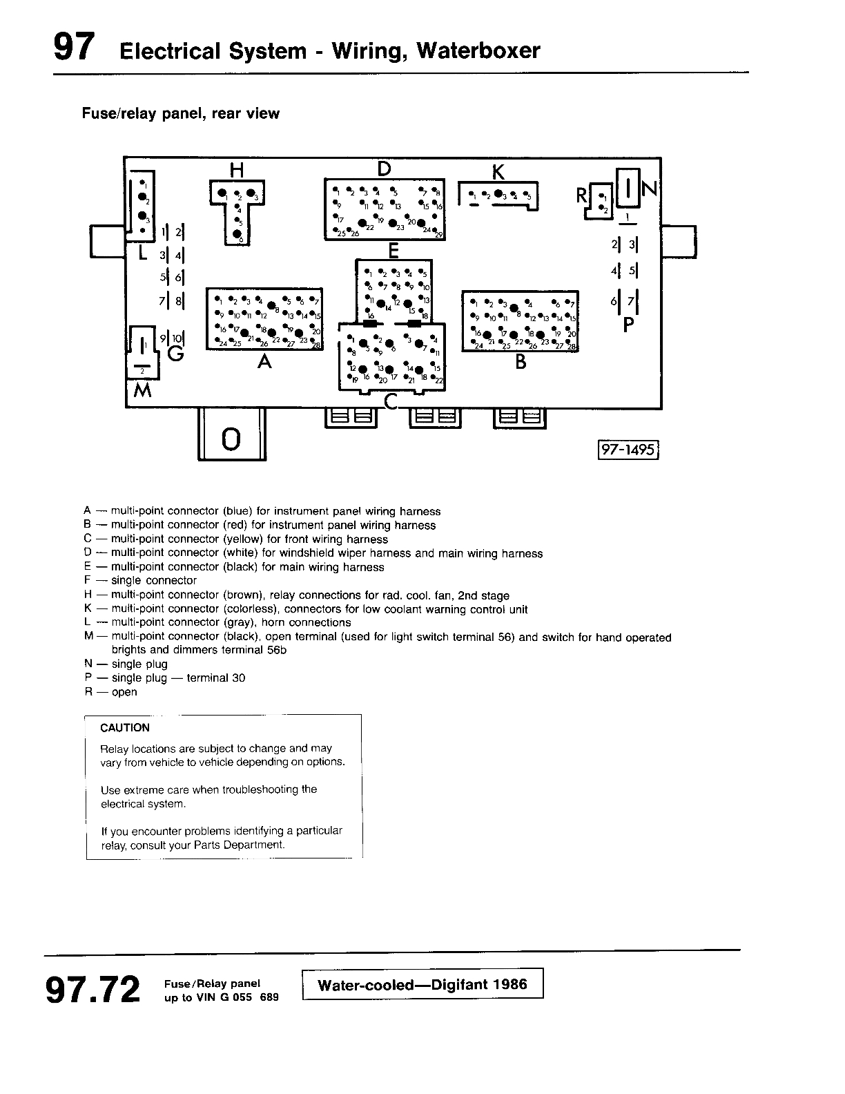
I choose terminal G9 on back of relay panel. Its on the right hand side as you look at the panel, a group of 10 spade terminals. G9 gets power when license plate lights get power, so it will supply power to chiming relay when light switch is on.
So that’s pretty well it, get the female spades of both the grey door switch wire and the new wire to G9 in the relay socket so that the grey wire goes to 86, and the newly installed wire goes to 85.
When installed, the obnoxious chime will sing out whenever driver’s door is opened and the lights are on.
Pics below illustrate somewhat, see the incomplete wiring to the seat belt warning relay socket? Only a grey, a grey/black, and the double brown ground are installed.
Edit 29/05/2010: had pics of wrong relay. Of course its not a “99” relay, the “99” relay is the programmable intermittent wiper relay. Proper relay pics inserted.


Boar et al
You know that expression? “it sticks out like dog’s balls”…


Hi-Lift/Jack-All jack adapter
Posted by albell in vanagon mods on May 11, 2010
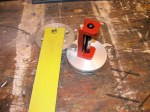
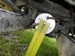
Here you go Michael, my home made adapter I made a few years ago. I cut up a stock Vanagon jack and welded the post onto some 4X3 1/8″ wall steel tube. The hole to secure the adapter to the jack, using a 1/2″ SS bolt and Nylock nut, was located to suit my jack. Nominal location given on sketch.
I could have welded about one more inch of the Vanagon jack onto the box section, looks like I only did 3″. As is it works fine, keeps the jack body clear of the Vanagon body. Note: as in all the pics on this blog, keep clicking on them to get the highest resolution. Most pics are 800 X 600 pixels, the jack adapter pics are 1000 X 750 pixels.
Addendum: you can buy commercially made versions, Go Westy sells one very much like the one I made, Gary Lee takes a different approach, see here.

Update: after taking measurements and pics, I realised it might look better painted. I gave it a shot of rattle can bed liner.
Horn contact ring
A question on the Samba about the “interchangeability” of horn contact rings made me get off my duff and fix a nagging problem of intermittent horn function on my ’86 Syncro. Someone in the past had made a fairly neat fix with copper wire to form a contact ring, but it only worked when steering wheel at a certain angle 🙂
I had a known good ring on the steering wheel of my ’82 Westy, so I whipped both wheels off, 24 mm socket (15/16″ also works) on nut, and swapped the contact rings. direct fit, no problems even though the steering wheels themselves are different. You just pry the ring out with a flat bladed screwdriver. Pics below show the two wheels and the home made contact ring. The larger of the two wheels is, of course, from the non power steering ’82.


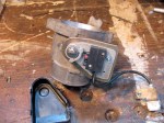
Throttle body fun
Yesterday I decided to take the throttle body off my ’86 syncro (2.1 l), to clean it up and double check the throttle valve position switch. Well it turned into one of those “why did I do that?” projects.
I had more than just idle curiosity driving me, the van had been having occasional lag in standing start acceleration which I thought might be due to the throttle valve position switch (TVPS), even though it had been recently adjusted. I was suspicious that the throttle shaft fit in the throttle body was loose and that might be affecting the TVPS.
Getting the throttle body off is pretty easy, I did find that the two bolts holding it onto the plenum were not tight, I wondered if that had allowed a little air leak? Who knows.
Got the throttle onto the bench and gave it a quick cleaning. Wasn’t as oil crusted as I had expected, someone must have been in here in the last few years. The TVPS had a black plastic cover on it, I had not seen that before. It sure keeps the actual switch nice and clean, see photos.
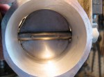
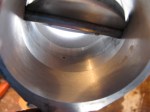
The bore and butterfly had wear in them, as expected. The design of the TB allows axial play and this lets the butterfly rub on the bore. The pics don’t show it quite as well as I had hoped. But there didn’t seem to much if any lateral play that would affect the TVPS setting.
Using a multimeter set on ohms and “beep” for continuity I check the TVPS setting. it was within spec, but I managed to fine adjust it to fall between a 0.003″ feeler gauge and 0.002″ shim stock. I was feeling pretty cocky at that point, and toddled back out the the van to re-install.
It was then I noticed the little clamp that connects the throttle cable to the TB was missing, argh. I must have dropped it between the van and the bench… probably on the gravel driveway. I spent quite a while searching, with magnet too, but no luck.
So I ended up making a quick and dirty substitute. Mild steel and a 5mm hex socket machine screw. It worked out ok.
I figured I’d blow the entire afternoon and take the crankcase breather tower off and check the O-ring that seals it to the case. The O-ring was as hard as hard can be, was it ever soft? It was also broken. The old ring broke into pieces getting it out. I didn’t have a replacement in the collection but I had a spare breather tower and I swiped the O-ring from that.
Cleaned up the oily mess from all the associated hoses, replaced some sections of braided rubber vacuum lines, and put everything back together.
The van runs pretty well the same, maybe a tad higher idle, will deal with that later. Needs a few more miles of driving before I admit it was all a waste of time 🙂
Next move… playing around with AFM spring tension. Yup dangerous grounds.


DOD corrosion study
Posted by albell in Uncategorized on May 6, 2010
Canadian armed forces review paper on corrosion control strategies. Good bedtime reading for insomniacs. Pdf, 824 kb.
p526285


Battery info
Nice little document with lots of good stuff on lead acid batteries and simple chargers (with schematics).
batterydoc
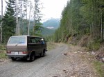
Weekend trip in April
Went on a quick overnight trip with my son. Ended up on a logging spur road between Cayacuse and Port Renfrew.
Then on to Port Renfrew and back around to home. Snaps below, note: roads were steeper, and snow deeper than they appear in the pics 🙂
The big Sitka Spruce (Harris Creeks spruce, and Harris creek also shown in the rocky sided gorge pics, taken at different points on the creek) is bigger than it appears. Base of tree as wide as the Vanagon is long.
Hey you trendy modern free heel skiers, don’t laugh at my mismatched poles and 80’s vintage TUAs with those wimpy bindings.
Oh and one more thing, skeleton pic… we found this just off a logging road. Looks like 2 skeletons in that pic, a third was a few feet away. No legs or skulls.
Update: looking at skeletons again, I’m guessing Black Bear. Lack of feet and skull good clues too.


Request for viscous coupling

If anyone has an old clapped out viscous coupling they would like to donate, please leave me a message in the comments. I’d like to take one apart, look at the seals, the plates etc.
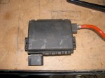
Auxiliary fuse panel
Posted by albell in vanagon mods on April 6, 2010
I found this handy little fellow on 2002 model year New Beetle ( I believe they are in Golfs/Jettas too). I used it on my 82 I4 engine westy, attached right on top of starting battery as an auxiliary fuse panel. I had it wired to an automatic charging relay (Blue Sea systems #7600) and “house battery”.
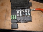
Its handy to have those 4 fusible links (2 X 110 A, 2 X 50 A) and 3 spade fuses to connect various accessories.
Addendum: I now have it installed in my ’86 syncro, mounted under driver’s seat. Instead of using the stock pigtail I’v introduced power from the Blue Seas ACR (which is mounted under passenger seat) into the box via the connection to the fusible link on the right. My auxiliary battery positive is connected to the next fusible link. I have tapped power via the 3 spade connection (with the spade type fuses) on the left:
-one to the kitchen unit for the water pump, fridge (not 12 V cooling function though), and indicator lights.
– one to my stereo head unit
– one to connection E3 on back of fuse panel (see this post)
Syncro running gear layouts
Nice to see it all laid out like this. First we have an overview of viscous coupling installed driveline. This has both rear and front differential locks.

Another view of same.

And here we have the much much rarer version. No viscous coupling, where it was is now a straight shaft. Power to front is now controlled by a de-coupler housed in nose cone of transmission.

And here is cross section of the front differential, showing viscous coupling install.

And a cross section of the rear differential and transmission.
![]()
Syncro front diff. removal
Posted by albell in syncro, syncro specific repairs on April 3, 2010
Look, its cold and windy today, hail at times. I don’t want to freeze in my cold workshop so I am sitting at the computer, ok?
Courtesy of Kafer and Co., Homburg/Einöd is this pdf file showing how to remove your syncro front differential when you want to swap in that new or rebuilt viscous coupling. PDF with pictures, about 800 kb.
A wide open viscous coupling
Graphic shots here from the Wikipedia entry on viscous coupling. I think they were supplied by some English chap who cut open a failed unit. Note the colour of the fluid, I wonder if this colour is due to old age break down, metal particles, or its the stock colour for the polymethylsiloxane and any additive the maker adds. The plates have either notches on the outside (engage with VC housing and flange shaft), or on the inside (engages with pinion shaft). The piercings on the plates are there to reduce heat induced warping. I think its the tiny burrs produced when those plates are pierced that are referred to in the abstract posted previously.


Might as well throw in a sectioned diagram of the VC to perhaps make things more clear.

