Archive for category vanagon mods
Vanagon – pop top hinge bolt replacement
Posted by albell in vanagon, vanagon mods on July 15, 2012
File this under “design elegance – fail”.
Quite a while ago I fooled around with homemade substitutes for the truss head bolts used on the pop top. The bolts which invariably end up rusting and staining the fibreglass. However I never did get around to replacing the hinge bolts, I had this notion that I was going to incorporate some sort of clever plate that would double as a roof rack mount. Well I never did do that and this morning I set about to make some simple washers. I used some aluminium round stock and some phillips head M6 X 1.00 stainless machine screws and produced clumsy, but effective, truss head substitutes. I suppose a good excuse is that I needed to make 8 of them and I really could not be bothered beveling the washers. Perhaps I still can make a roof rack mount and incorporate these clumsy things.
Important note: one has to be careful that the bolts/screws used are only long enough to just go through the 10 mm nut on the backside of the hinge. If too long, the bolts will hang up on the hinge when the pop top is lowered.


Vanagon – oil pressure sender relocation
Posted by albell in vanagon, vanagon mods on July 5, 2012
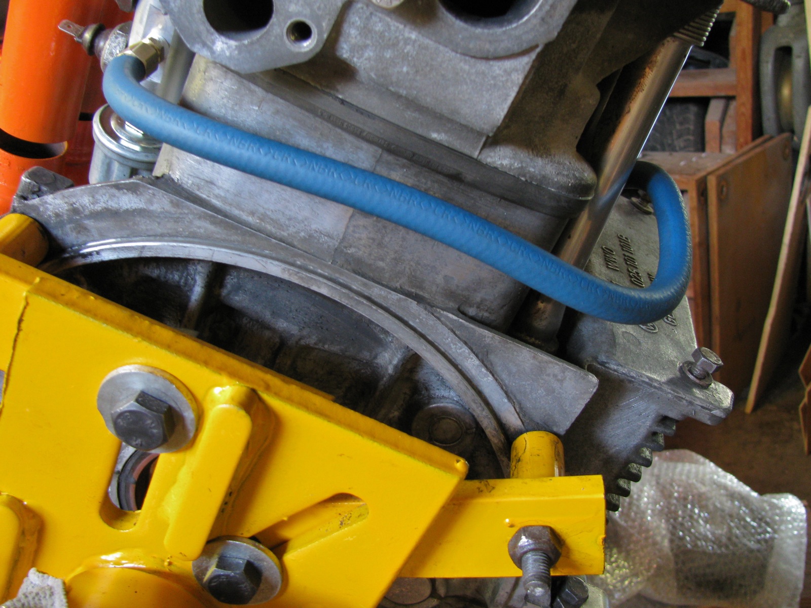
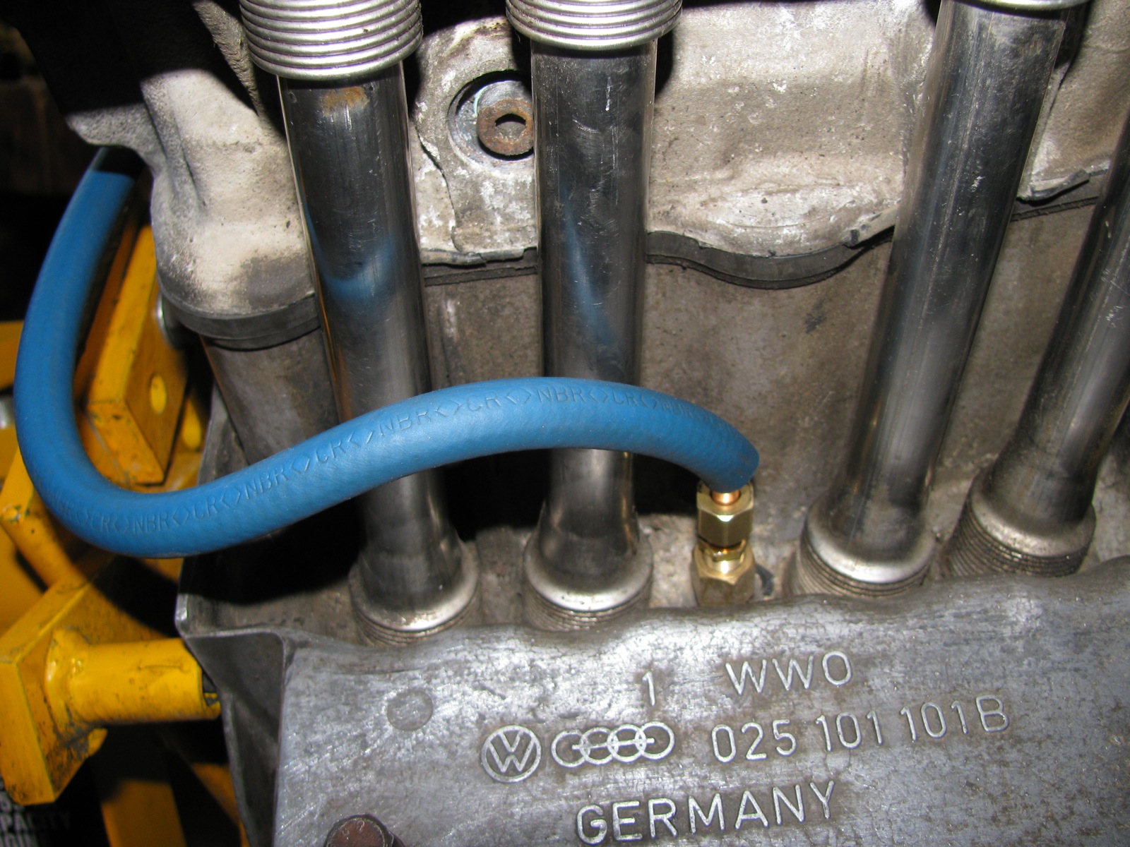
Been fooling around with relocating the high and low oil pressure switches so that I could add an oil pressure gauge sender and an oil temperature sender. There are commercially available kits to do this, but once again as I am cheap and keen to use the lathe, I made my own version (heavily influenced/inspired by Tencentlife’s work, shown here). A bit of aluminium rod, machined some flats and tapped some holes, some 1/4″ soft copper, compression fittings and a bit of fuel line to cover the copper. I used my spare motor to mock up install, probably needs more tweaking in the line, and will perhaps have to make a hole/slot in the rocker shield. Relocating the rearmost (is it the low pressure or high pressure? Can’t recall – ok, low pressure sender on left side, between pushrod tubes, high pressure sender on rear, below and to right of oil filter mount boss) sender frees up that spot for a temp sender.


Vanagon – another use for scrap aluminium
Posted by albell in syncro, vanagon, vanagon mods on June 25, 2012
This time a bit of aluminium grating and it couldn’t have been easier to make – I cut it into two sections. Looks like it might work out in the field using rocks or wood to raise one end. BTW, my transmission bash plate seems to have generated a lot of chatter about increased transmission temps due to reduced air flow over the transmission. As with most internet chatter, no data given to support opinions but I hope to be able to do some temp measurements using IR gun (yes Simon, I’m going to ask to borrow it).


Vanagon – syncro bash plate project finished
Posted by albell in syncro, syncro specific repairs, vanagon, vanagon mods on June 24, 2012
Well the transmission protection part anyway. I decided to leave the plate mostly rectangular, but I did have to curve the front corners for no other reason than I thought it looked better. I also drilled some drain holes at the rear of the plate. Instead of using the drill press, I used the wrist buster, aka Van Dorn drill.

I made rather ugly holes with it, but I rationalized that (and other goofs) with the “it’s only a skid plate” mantra. I cut out slots for the stock skid bars and bent up the leading edges slightly. You can’t bend up that middle section too much or it will hit the nose cone of the transmission. I also gave the bottom of the plate some DA love.

I found it a real pain in the arse installing the stock skid bars by myself, but installed they were. See how exposed the transmission appears? Like having your goolies hanging out.

And same view with the plate installed.

Front view.

I think the extra width will help protect the inner cv joints and the fuel pump. Note to Simon, will also protect the speed sensor and that big electrical plug on driver’s side. But not sure about fitment around exhaust on your 2.5 Subie.


Next job will be to add some 1/4″ aluminium plate between the propshaft protection bars, and perhaps to extend that protection out sideways and attach to frame rails. That will help protect shift linkage and coolant hoses.
Damn. just occurred to me, forgot to paint the stock skid rails where I ground off the paint for welding the tabs on. I guess the project is not quite finished.
Vanagon – syncro bash plates project
Posted by albell in syncro, syncro specific repairs, vanagon, vanagon mods on June 22, 2012
I left the entire syncro drivetrain protection bars off my van after the propshaft business with a mind to installing some bash plates. The transmission is left pretty well fully exposed in the stock set up, and today I started doing a bash plate in that region. I had some scrap yard sourced 5/16″ aluminum plate to use.
Here are the stock skid bars/rails, transmission end. See the added tabs?

I had my first go at TIG welding…I still have a long way to go.

A real welder (good friend Dave) did the stainless to plain steel weld (609 rod).


Pretty heavy gauge aluminum, but it was cheap.

I match drilled and countersunk holes in the plate to match the nuts on the rails. The tabs with nuts were not located with any special measurement in mind.


Other side view. I’ll offer the assembly up to the van and see how much of the plate I’ll cut away. Rough sketches on plate sort indicates my thinking, “wings” towards the rear to provide a little protection to the inboard cv joints.

Project finished, blog post here.
Vanagon – GoWesty Wasserstopper rain fly hook issue resolved
Posted by albell in vanagon, vanagon mods on June 8, 2012
I received replacement hooks from GoWesty for the Wasserstopper rain fly. I had complained that original hooks held on to the gutter poorly. Good customer service!
The replacements do hook on to the rain gutter much more securely, but I haven’t had the chance to fully test with them attached to fly.
My best pic of original hooks, they end up hanging on by fingernails.

Replacement hook.


Vanagon – making new syncro propshaft internal bushings – Part one
Posted by albell in syncro specific repairs, vanagon, vanagon mods on June 6, 2012
I have my propshaft off while I try and track down my transmission noise (see previous post). Some helpful syncro owners over on the IG16 forum suggested that I look at my propshaft as the source of the noise. Well why not eh?
This is a story of mistakes and ignorance. When I compared my two propshafts in this post, I mistakenly concluded that one shaft had thinner walled bushings than the other. Well it did look that way and both assemblies felt equally tight – ie acceptable fit of shaft into bushings. But I think I must have been wrong for when I examined the “thin walled bushing” propshaft (the one I just removed from van), I could detect play in the bushings. The rubber giubo and the internal O-ring have been removed and dial indicator set up to measure movement as I lifted U-joint yoke up (trying not to rotate joint as I did it).
Here is diagram of that end of the propshaft just to refresh memories.

And my measurement set-up.

And short movie showing movement.
I admit to this being not an extremely accurate way of measuring the radial play, was hard to just move the yoke up and down and not rotate it. But I could feel the play and it was more than I think it should be.
So it comes down to replacing the bushings. The outer one would be relatively easy, but the inner one is a different story. And I think the inner one is important to be snug as it is at the end of the shaft and would limit shaft movement more than the outer bushing. That was a convoluted sentence, I hope you get the idea.
On the Yahoo Vanagon Syncro mailing list, the bushings have been discussed a few times. One list member wrote (a year ago?) that the inner bearing could not be replaced as it sits in a recess in the tube and was probably installed before that end was welded onto the propshaft. The drawing at top of this post does not really show the recess (drawing too small), and I had forgotten all about it.
Foolhardy is a useful adverb to use whenever I get it into my head to fix something. I kid myself that I know what I am doing, ha!
I pondered how to remove the inner bushing and came up with chiseling it out. I have this neat little 1/4″ chisel that looked like it would work.


And off I went, chiseling a groove down the inner bushing. It took a couple of groove before I could break out the bushing. I found it difficult to get a good pic of what was going on deep in there, but in this pic you can see a section of the bushing folded inwards. Sharp eyed readers will be able to see that there is a lip in the tube which locates the bushing. Bushing was pressed in from other side, then that end cap inserted (portion of bushing is obscuring the hole in the center of that end cap), and then assembly welded to propshaft. Even sharper eyed readers will notice another, smaller lip about halfway between inner and outer bushings. I overlooked this, I have no excuses why and it bit me on the ass later on.

Bits and pieces of the bushing. After I knocked the fragments out I could see the aforementioned lip. I didn’t feel very happy at that point.

I really had no choice but to go on and cut out the outer bushing. This pic shows how well the chisel cuts the bushing and the underlying steel – doh!

Note the fretting or corrosion on the surface of the bushing. Here is a close up of a fragment, looks a bit like sintered bronze, like an “Oilite” plain bearing.

So alright then, what to do about the inner bushing problem? I wasn’t about to cut the end off the propshaft. I settled on the idea of turning down the diameter of the end of shaft a tad, to about 23 mm from 25 mm (diameter at end where shaft inserts into bushing) and making that reduced diameter area about twice as long as the original bearing surface. I reasoned that a Delrin bushing could be made to fit into tube, be supported by the tube and extending on unsupported over the original bushing spot. Jeez, I need a diagram to explain.
Here is a cartoon cross-section of the end of propshaft that houses the bushings.

And with shaft in place.

Modified shaft.

And assembled with new bushings.

The drawings are not to scale and are meant just as sketches to get my idea across. Important thing to note is the new internal bushing will come further up the shaft, and be unsupported in old bushing area.
Off to the lathe!
Mounted yoke shaft between centers, was lucky and set up resulted in less than 0.001″ run out at end (inner bushing area).

Then turned the end down to 23.00 mm. I found it hard to get a nice surface finish even with very light cuts. I was using a round nosed HSS tool bit (has given me nice finish on other jobs), but this time I had problems. So, a less than perfect finish.

Chamfered the end and gave it a quick polish. I think it will be good enough.

Next step is to make the Delrin bushings. Whoa, slow down sonny! Have another look inside the propshaft, it is not quite the same as you describe in your sketches. Go on, look at that picture you took of the bore. What? No! Really? , let me… well gosh darn it.

I missed this before I thoroughly cleaned out the bore – the bore is machined out slightly for a little way, above the machined out area for the internal bushing. Illustrated, but exaggerated and not to scale, the slightly bored out region is not as large a diameter as illustrated, but it still screws things up for me.

So my original plan of a longer internal bushing will not work, see?

I decided to make the outer bushing, classic avoidance behaviour. I actually made 2 outer bushings, first one really as a practice piece, second one with a lip. I also went ahead and, again for practice, made the now discarded inner bushing concept.
Delrin rod (1.5″ diameter but turned down a tad before this shot) and boring out to fit yoke shaft. Gotta love that chipped cutter I am using, funny thing is that it does a nice job on this plastic.

Bored out to size, 25.00 mm.

I made a quick and dirty mandrel to mount bushing so that the outside diameter could be turned to size.

Then to get the bushing off the mandrel, I bored out the end of the mandrel.

To make the “practice” inner bushing, I first bored out Delrin to size, parted off, then mounted oversized bushing to yoke shaft to machine down to size. Note the outer bearing installed first. Makes you wonder if I hadn’t realized the issue with the propshaft bore yet, doesn’t it?


As I mentioned before, I went on to make another outer bushing and gave up for the evening.

Back to the problem of, in essence, installing a bushing from the wrong end. How about making the bushing the squeezing it to deform enough to be pushed in the bore and end up in position, then use a tool to form it back into shape, against wall of bore? Nope, daft. Well how about taking propshaft to machinist to bore out? Well, that might be the fall back solution. Ok, how about a split bushing? Would that allow the bushing OD to be reduced enough to be pushed in and then expand in correct place? Mmm, maybe, worth a try?
Something like the Iglide Clip2 plastic bushing (but without the end flange)?

The nominal diameter of the bore is 26 mm, and where the internal bushing is located, 28 mm. Circumference of bushing should be (pi X 28) 87.96 mm, and to fit in through 26 mm bore, 81.68 mm. So slot in bushing needs to be at least (87.96 – 81.68) 6.28 mm. Seems like a large slot to be cut. One thing in my favour is that the yoke shaft does not fully rotate in the bushing, just a few degrees allowed by the flex in the Giubo. A diagonal slot as shown in the Iglide bushing above would provide better support of the shaft so it is worth a try cutting the slot that way.
This post is getting rather long and rambling and I have other work to do, I’ll try making the split bushing later and report back in another blog entry. Feel free to give me a hard time in the comments section, I deserve it 🙂
Vanagon – trying some things to make the GoWesty rainfly work a little better
Posted by albell in vanagon, vanagon mods on May 26, 2012
UPDATE – 29/05/2012 – I posted my attempts at fixing the gutter clip/angle/hook issue on the Samba and a member responded that there may have been a mistake made at Go Westy with wrong hooks being sent out. So I emailed Go Westy, outlining the issue and I got a quick response of new hooks to be sent out to me. I am impressed by this prompt customer service, well done Go Westy.
I spent a couple of hours playing around with the fly, wanting to fix- what I see as problems – the gutter angles/hooks and the front strap system. Previous post about fly here.
I’m just using what I had on hand, and this is only preliminary stuff.
I had some longer metal hold down hooks, I sewed some velcro on to them. These hooks have a more obtuse angle on them compared to the Go Westy ones. I also attached some webbing attached hooks and buckle for the front straps. I added some silicone tape wrap to those hooks.

The new angles are longer, so I stuck on some velcro to the clip itself to provide a bit more area of velcrotude.


The new angles/clips do seem to hold on firmer.

Where my ShadyBoy awning is, I left the stock hooks, they are fed up from below and the hook part can’t pass through the space. I was dumb not to see this way before, I said in my previous post about the fly that it was not possible to attach these hooks, doh.

The front strap mod is not so successful, but not completely ass.


An annoying curl in the material at the front.

Well, it is a start, I’ll be trying to get it a little better. I’m not happy with the front strap idea.
Vanagon – front door speaker mounts
Posted by albell in vanagon, vanagon mods on April 5, 2012
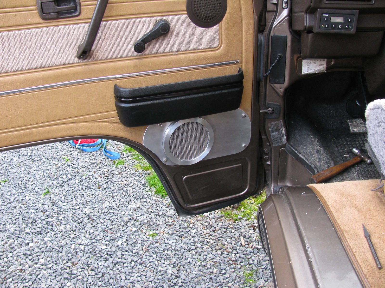
Update: I painted the mounts and grill. Blog post here. I think the paint holds the grill mesh in a dome shape better than no paint.
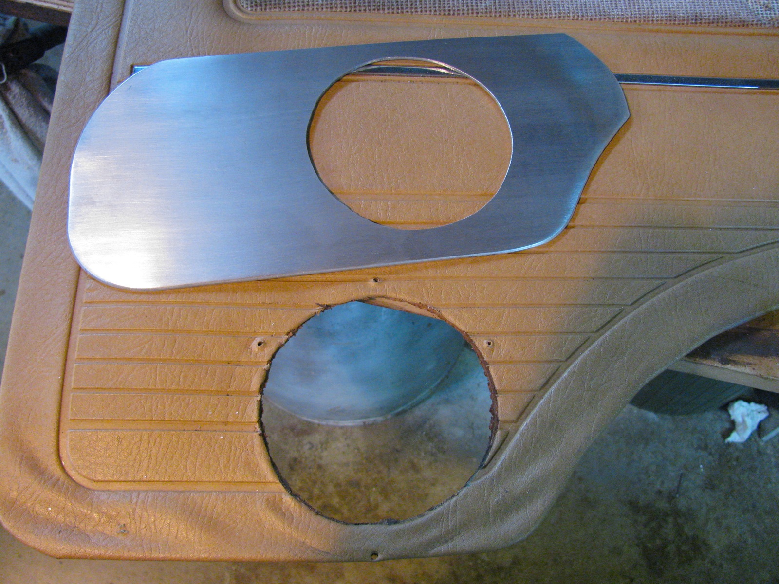
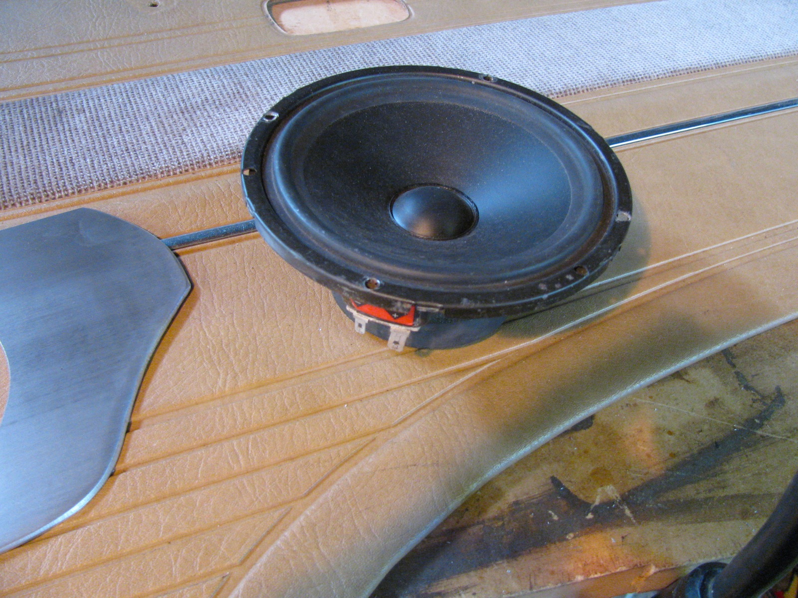
The door cards on my ’86 syncro were falling apart down where the previous owner had installed 6″ Boston Acoustics speakers. Really, the entire door card is pretty tired and warped but I chose to just do a quick and dirty reinforcement around the speakers. I used some scrap 1/8″ aluminium sheet to cut out a plate to stiffen the bottom of the card, some 1/2″ plate was turned down to make new bezels for the speakers, and some stainless steel mesh to make new grills.
It turned out more rugged utilitarian looking than elegant, but much better than before. Oh btw, there are tweeters behind the stock speaker grills up higher on the door. The crossovers are tucked up under the dash.

Simon’s hightop painted
Posted by albell in syncro, vanagon mods on March 17, 2012

")
Vanagon – VW pop top insulation
Posted by albell in syncro, vanagon, vanagon mods on February 13, 2012
Borrowed from good friend Simon, this genuine accessory is supposed to be installed outside the pop top but with the rain fly on, I thought I’d see if it was able to be installed inside. A little bit of a wrestling match, but it goes in and stands up by itself. Hey, notice I still haven’t installed an upper bunk.


Vanagon – Go-Westy “Wasserstopper” rain fly
Posted by albell in syncro, vanagon, vanagon mods on February 13, 2012
Note: clip fitment issue resolved, see this post
A Xmas gift installed. Over all pretty good but I don’t like the side clips that are supposed to hook on to the rain gutters. They have a too tight curve and don’t grip well. Also, the strap that goes in the front doors and hold the front of the fly down tight to the van is not that great of a method. I’ll try modifying both. However, as is, the clips do attach to the Shady Boy awning box. No way to get them to attach to the gutter with the awning box in the way. Link to Go Westy product page here.


Vanagon – Small Car stainless header failure
Posted by albell in syncro, syncro specific repairs, vanagon, vanagon mods on February 12, 2012
Was installed new about a year ago, in a EJ25 powered syncro. I suppose disappointing would be one way to describe it.


Vanagon – picking up a high top
Posted by albell in vanagon, vanagon mods on February 11, 2012
The start of Simon’s big adventure, a “Get-Away” hightop rescued from a decrepit ’82 Vanagon and taken to Simon’s place.


")
")
Vanagon – Jim’s sunvisor clip mod
Posted by albell in vanagon, vanagon mods on January 31, 2012
Another from the Felder Files©, modifying sunvisor clips on early (pre ’85?) to accept later model visors. I’ll let Jim explain:
“And please excuse the casual reference to “early vanagons.” The problem may
be limited to early Westies, but since I do not have an early non-westy
around to check, I”ll have to let you do that.
The main problem is that by now, the early-80s era sunvisors (which weren’t
all that great to begin with) have become sagging bags of foam dust. I have
tried everything I could think of to rebuild them. It’s a lot of work with
mixed success.
Online parts vendors stock them, but they tend to be for one side or the
other, not a set, don’t have a mirror where they should, and are hideously
expensive.
The world is full of very nice, late model padded visors in great shape. So
why can’t we use them?
The problem is easily noticed if you install them. The very end (near the
mirror) of the visor beyond the point where it snaps into the the visor
clip has just a little too much meat on it. Everything else lines up,
screws all fit, no mods needed, everything is nice–until you operate the
visor. When you do, you rotate the visor through almost 180 degrees,
thereby smashing that “meaty” part against the hardboard ceiling, and
levering off the top part of your clip in the process.
If you are handy with a hobby saw, and sandpaper, and have access to a set
of four clips that can be combined into two, you can have a very nice set
of late-model visors in your early vanagon. Did I mention that you could
have a lighted mirror on the passenger side?
I have pictures to send to those interested, but basically you take a clip
and an x-acto hobby saw and you saw the top (the part with the clip, sure,
you can used a broken clip for this) so you have a base with a flat top and
no clip. You take another one and saw off the clip as low as you can. You
glue the two together into a unit that looks like the original only about
1/4 inch taller. You sand the sides so that no excess glue show, and
install as usual.
Some may comment that it would be easier just to make a base out of some
plastic material that raises the unit, but if you get into it you will see
that there is a molded plastic tang on the bottom that fits into a square
locator hole where the clip goes. Unless you are prepared to recreate and
attach this tiny tang, you are better off with the procedure described
above.
It just works great. Time will tell if the epoxy has trouble sticking to
the plastic of the clip. I will report in due time.
In the first picture you can see more easily how the cuts were made. You can see the lip of overhang on the top piece that will be sawn off when the epoxy cures.
The second picture shows the piece trimmed and sanded, ready to install. ”


Vanagon – silliest toaster ever
Posted by albell in metalworking, vanagon, vanagon mods on January 13, 2012
Fever dream realised with some scrap aluminum tubing and some stainless steel mesh. Space efficiency? We don’t need no steenkin’ space efficiency.


Vanagon – LED dash/control lights – commercial improvement?
Posted by albell in vanagon, vanagon mods on December 19, 2011
You know how I have complained that the beam pattern from my home made and Van Cafe sourced LED gauge cluster bulbs is not optimal. The “standard” type LED projects most of the light through the end of the diode, and even if you grind the end of the diode at an angle, or have ones that are flat ended (Van Cafe) it does not improve the beam dispersion that well. The stock incandescent bulbs project light from the sides as well as the end, and the bulb holders are designed to take advantage of that.
Well it seems that Go Westy are selling LED bubs that might address this problem. The heater control light looks like it has SMD units on the sides in addition to one on the tip. This should really make a difference. But jeez, expensive little buggers eh?
Go-Westy’s cluster bulbs do not have side mounted LEDs but appear to use a SMD unit. My limited experience with SMD LEDs makes me think that they have a much wider beam dispersion than the bog standard LED.
I have not tried any of Go-Westy’s LED so I am speculating based on the pictures.
Addendum: I’m remiss in not thanking Tom for the head’s up on the Go Westy bulbs. Also, I don’t want to appear to be endorsing Go-Westy’s stuff, I am not getting any kick-backs, sadly 🙂
Vanagon – digital clock LED light improvement
Posted by albell in vanagon, vanagon mods on December 7, 2011
Quick mod to improve the lighting of the digital dash clock. I replaced all of the incandescent lights in the dash with LEDs some time ago, but you know how the light dispersion on a LED is much more restricted than that of an incandescent and it really is apparent in the digital clock. This German fellow thought the same and went to some trouble to fix things. I tried one of the hacks he discounted – installing some reflective material.
Clock apart, some adhesive backed aluminized foil stuck in to reflect the LED output to the 2 light pipes on each side of the clock face.

Clock back together, you can just make out the led close to the peak of the mylar foil.

And how it looks installed. Notice how bright the tach and speedo faces are at the top? I had put some of the same foil in the light housings hoping it might improve the light from the LEDs up there, but it seems to have just accentuated the poor beam pattern. Camera setting does make it seem worse than it is in reality.

Also not that the little black shade is missing, or slipped, from the tach light housing. Here is the housing with foil.

Still more work to be done with this idea.
Vanagon – heater control light, LED hack
Posted by albell in vanagon, vanagon mods on November 25, 2011
Years ago I made some LED lights for the instrument clusters before they were commercially available. They didn’t look pretty, but they worked. On my old neglected website I have some pics and text.
I still have those early models.

If you want to see how to make a much neater version, check out this German site. Don’t miss his clock lighting fix either.
I also hacked up a heater control bulb/socket to take an LED. I am embarrassed to show this effort, but as ugly as it is, it does work.

So embarrassing that I had to have a go at it again. Here is a burned out stock bulb/holder.

If you look closely at the slot in the plastic you can see a thin copper wire attached to the silver spade connection. Right adjacent to the “step” in the plastic the spade has a bent inward tab that secures the bulb and the spade in the holder. Bend up that tab (one on each side of the holder) and the bulb and spade will pull out.

I clipped off the bulb and then soldered on a resistor. Btw, you can decode that resistor value yourself 🙂 and there are online calculators to determine what resistor to use using led voltage rating and supplied voltage.

Then the spades were soldered on.

And the whole shebang pushed back into the holder. The resistor prevents the led from being inserted fully, but it is pretty secure as is.

Not perfect, but a whole lot better than that early mess. I’ll take some pics at night to compare with the stock incandescent.
Update Nov 28 2011 – being absent minded, I installed the led modified lights in the heater controls and the rear heater fan switch without taking pics of before swap. To be honest, it is a bit of a “meh”. It does match the rest of the dash now, but I can’t help but wanting something better, brighter. It was a 10,000 mcd LED in the heater control light, pretty bright I thought, but not as bright as I want.
Vanagon – changing the colour of cool white LEDs
Posted by albell in vanagon, vanagon mods on November 23, 2011
Last year I bought a set of LED festoon lights to replace the interior lights in the van and one for the glove compartment/map reading light. For some reason I bought cool whites for the interior lights and a warm white for the map light. I tried to convince myself that the cool white gave a clean and modern feel (ha!), but no, as friend Simon puts it “it’s like a morgue”. I have 4 door activated interior lights; driver’s door, passenger door, and one on each side at the back seat area. So the morgue effect is throughout the van. In contrast, the map light does give an acceptably warmish cast.
I suppose I could buy new LEDs, warm white, but no, I have to try another route. I was talking to the lighting guy at a local theatre and we got onto the subject of lighting gels. I explained the morgue situation and he gave me an old Lee 204 gel. The specs for this filter can be found here.
Here is the filter:

I cut a little strip and wrapped it around the festoon LED and secured it with O-rings. I thought that just putting a rectangular bit of filter in the light housing would allow some cold white to “leak” out of the ends.

Back into the light housing.

And the result? Well it is different, warmer. Will have to wait until dark to really be sure it works, but the comparison pics are promising.
Unfiltered:

Filtered:

Update: After dark test – still not as cozy as incandescent lights but much better than before.
Vanagon – sliding window rain screen – improved
Posted by albell in vanagon, vanagon mods on November 17, 2011
My friend Stephen improved my sliding window rain screen by making larger cutouts at all four corners. I think this will keep out the rain better.
Update Feb 4 2020.
Here is a very quick and dirty pdf drawing of the screen. My old draughting teacher would be appalled. The width of the screen could be adjusted to suit, my first version was narrower.
window-screen-drawing-v1-1.pdf


Vanagon – sliding window rain screen
Posted by albell in vanagon, vanagon mods on November 15, 2011
Simon’s van is modelling a quick project made with a bit of scrap 1/8″ Lexan. The dimensions are 7.5″ X 17.5″, and the corners on one side cut out (about a 1″ radius). The idea is that the screen stops the rain from coming in the sliding window when it is opened for ventilation. To be field tested, I don’t know if I made it too long, it bulges out a fair bit.
Update: see here for improvement.


Vanagon – Westy kitchen panel graphic
Posted by albell in vanagon, vanagon mods on November 11, 2011
Jim Felder made this up, kudos to him. He writes:
“Today I got ambitious on a project I have been wanting to do for a long
time. It’s a replacement overlay for flaking, peeling and rusting front
panels for 83-up vanagons. It’s in brown, of course, because that’s what I
have. If someone will scan a grey one, I will make that version available
(I need to get the color right… if someone just wants to scan and sample
the CMYK mix in photoshop, that will work too).
You should be able to have this printed out on a variety of substrates,
depending on the capabilities of your local sign shop. Cut out the holes
for the LEDs (white circles, you may even be able to get this printing on
the backside of lexan with clear windows for the LEDS instead of punching
them out). Remove your old metal panel and sand and respray it. Cut the
printed file out at the outline, it should fit exactly within the debossed
inset of your panel.”
pdf file here:
Here is a jpeg version:

Vanagon – D15 connector issue
Posted by albell in syncro, vanagon, vanagon mods on November 2, 2011
Yesterday, driving the ’86 syncro, going down a long hill and the van died (noticed when throttle re-applied). Pulled over and it started back up after a couple of tries, funny I thought. Got to my destination and parked for a few hours. Then I tried to start the van and it turns over and catches for a second then dies. Try again, same, then subsequent tries has it turn over but no start. Noticed no fuel pump noise with ign on (and my van does cycle fuel pump with ign on.)
Looked in the engine compartment with ign on. No hum from idle valve. Pulled the fuel pump and ecu relays and replaced with new (during which I jumped contacts and did get fuel pump to run). No change, no idle valve hum and no fuel pump, and no start.
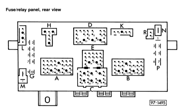
Then I pulled cover from fuse panel and pushed on fuses and generally jiggled panel. Fuel pump cycled on, and I could start the van. Drove home with no problems. I suspected the known problem of the D15 connection on the back of the fuse panel. This connector supplies power from ign switch back to engine compartment and can power (depending on van year and VIN) the fuel pump relay, the idle control unit, coil, and the crankcase breather heater. Gets a little muddled in that the crankcase heater was retrofitted to early ’86 vans (and that seems to be the situation in my case). The wiring diagram shown below is specific to my van.

No matter what version you have, the D15 connector is oveloaded. Note in the diagram there is another connector in the “D” plug that is on same current path as D15. This unused connector, D23, is a bigger Molex than D15. Today I pulled the fuse panel down and removed the “D” plug. D15 looks like it has overheated.

I couldn’t find a spare larger Molex connector to make the switch over to D23, but I did put a new connector on the black wire to D15 and spliced in a pigtail so that when I get the right connector I can plug in to D23 (see the unused larger hole at the bottom?).
Update: I did finally find a large female, molex type, connector for that pigtail, and it is installed into D23.
I can’t say for sure that this connection was responsible for my no start problem yesterday, seems likely though.
Addendum: dug up the Samba thread on this subject, worthwhile reading.
Vanagon – nice find at the wreckers
Posted by albell in vanagon, vanagon mods on October 18, 2011
No heating element for the seat, but the switch and the relay/controller (and wiring). I understand the 2 seat switch will fit in same hole in the steering column upper cover, but of course will need an additional relay/controller.

Vanagon – power mirror repair
Posted by albell in vanagon, vanagon mods on October 5, 2011
I have manual mirrors on the syncro and they are less than satisfactory. They are small, don’t stay adjusted very well (I have gone through all the tricks to keep them adjusted), and they frost up in winter. Now I finally have collected enough used parts to get 2 power mirrors installed, as yet not powered, and not without having to bugger around to make them work.
I have one white one, complete but the heating element connection broke, and one black one which also had the same broken connection plus a broken stem. I’ll deal with the black one first. By the way, the mirror had been “repaired” by its previous owner using duct tape and lots of shoe-goo. What a pillock.
Here is a shot of the socket showing the broken stub.

And here is the part that was broken off.

The bracket that receives this stud looks like this.

The stud passes through that bracket and is held in place with a nut and spring arrangement. The lumpy end of the bracket fits into corresponding divots in the socket on the mirror arm, you can see them in the first picture. Here is the spring and nut on the broken stud. The white thing is a plastic washer, but it was cracked and not reused.

A new stud had to be made and affixed to the mirror. I had an idea and, not surprisingly, I discovered that someone else had the same idea before. SpitsnRovers posted his fix on the samba. As an aside, his website has some pretty useful Vanagon info on it. It is just a matter of tapping for a new stud to be screwed in. The stud has a 13 mm X 1.5 thread so if I had a bolt with that thread and the corresponding tap, I would be in business. But I didn’t so I wasn’t. I did have some 1/2″ NC bolts and the right tap, why not use that instead?

I used the die to make the threaded portion of the bolt a bit longer. The bolt was chucked up in the lathe and drilled out (passage for the electrical wires). Oh I am so clever eh? Well, no. I drilled the hole a tad to large.

Found another bolt and drilled the right sized hole. Shown below is the drilled and cut bolt, a 1/2″ Nyloc nut, the stock nut, the broken plastic washer, and the spring. I feel like I am becoming even more pedantic.

I then enlarged the hole in the socket and tapped some threads. Not much meat there though.

I cut the drilled out bolt to the right length, actually a little longer than the broken stud, and threaded it in with some locktite and set it aside overnight. To be honest, I had my doubts whether the stud will hold, there are so few threads engaged. Righty-oh, next day I put it back together. I used a 1/2″ Nylok nut instead of the stock slotted nut, but here it is assembled onto the bracket with plain nut (that broken plastic washer was discarded later).

It withstood cranking down on the nut, the threaded stud did not pull out. I set that aside and had a look at the mirror glass itself. The glass is glued onto a molded plastic backing, with a metal heating element sandwiched between. There are two tabs bent up from that metal that connect to the 12V power supply wires. Here is an intact tab.

One of those tabs was broken (same thing with the other mirror). I tired to solder on a new tab, but no luck, the solder would not flow onto the metal. Time for the cheesy fix, I could lift the plastic backing up from the metal enough to slip the bare end of a wire in. It helps of you heat the plastic with a hot air gun. The wire was trapped and it made electrical contact. I tested it by popping the mirror into the freezer for a while then connected a 12V source to the tabs and watched the fog disappear from the glass. To make the cheesy fix even more obvious, I dolloped a bit of silicone onto the area. This picture is of the repainted white mirror (Krylon Fusion satin black) and you can see the same repair on the back of the mirror.

I routed all the wires (mirror motor and heat) and put the darn thing together. I’ll post more about the wiring when I get around to connecting the electrics to the van, I’m happy right now to have the bigger mirrors. The repainted white mirror was put together, minus that broken white washer.

Not quite the right sized screwdriver, but close, and German. So you know it has to be complaining about my lack of mechanical skill.

And a final shot.

A word about the electrics. The heating element supply is connected to the rear window defogger circuit, so it gets power when that is switched on. That will be a simple connection. The adjuster motor (and its little magnetic clutches) is wired to a control switch mounted on the driver’s side door. I have to find a switch. I believe some mid ’90’s cabriolets share the same switch? I’ll document that sooner than later, I’m keen to see the mirrors move and de-mist.
Vanagon – looking at pop top truss head bolt alternatives
Posted by albell in vanagon mods on September 23, 2011
I hate the truss head bolts used on the Vanagon pop top. They are hard to unscrew and they rust. Some vendors sell stainless steel versions (it is a M6 x 1.0, 20mm long). Phil Z. used oval head stainless machine screws stainless cup washers (he filled the back side of the cup washer with thickened epoxy), and they looked pretty good. But I wanted try something else, something with a big head and that looked good, I only had 50% success. I made a cup washer of sorts from 1/4″ aluminium and used a M6 machine screw and I think it looks a bit odd.

I had another go, this time with the bolts that fix the pop top assist struts to the fibreglass. A bit better looking or maybe not.
 On the other hand, they don’t look *that* bad, and certainly better than what was there before. Who am I kidding? The last one looks like crap. Here is another attempt.

Vanagon – cleaning the Shadyboy awning
Posted by albell in vanagon, vanagon mods on September 16, 2011
After about 5 years of use my Shadyboy awning was looking a bit dirty. I contacted Wolfgang at Shadyboy and he confirmed that the material can be cleaned with soap and water. Here are some pics I took, padding the post a bit, but maybe someone would be interested in how the awning looks non-deployed.

Some of the dirt must come from keeping the guy line stakes in here.

Unrolled, you can see it is a bit manky.

There are silicone plugs at each end of the grooved aluminium extrusion that the inboard seam awing slides into. The seam has a flexible rod sewn into the hem. The plugs can be pried out with a flat bladed screwdriver, just need to do one end.


With the plug removed, the hem slides right out. Notice the gap between the aluminium block with the hole drilled in it and the case? Seemed like the case might have been bent away from the block, I used a little C-clamp to draw the case back closer to the block.

I hand washed the awning using warm water and a very little bit of laundry detergent. I rinsed it well, and I noticed the water beads up and slides off the material just like it used to. Then the material was fed back into the groove and the silicone plug installed. Before and after shots.


Vanagon – headlight relay upgrade
Posted by albell in vanagon, vanagon mods on September 15, 2011
Some sort of planetary alignment must be happening, I’ve been talking to a few Vanagon owners about headlight relays, so I thought I’d post a couple of diagrams. Adding headlight relays to the van is a good idea, it redirects headlight power current away from the hi/low beam selector switch and the headlight switch. By passing the switches helps to maintain a good voltage to the lights and most likely prolongs the life of the switches. Also, if upgrading the lights to higher wattage bulbs, then relays are a definite requirement.
First off, here is a diagram I made years ago when I did the mod to my ’82 westy. For some reason I think the diagram has an error in it, can anyone see it? Seems silly to post a schematic that I am not 100% sure of, but on the other hand if one was to study it to find the error one would come away with a better understanding of the headlight circuit 🙂 Oh, one more thing, if I was to do this over, I’d run separate fused power for each relay.
Note: Mark Drillock pointed out that: “For the early diagram there are a couple things I would change. The red wires to the headlight switch and hi/lo switch are both labeled as coming from fuse S9. This is not really true and misleads people into thinking those 2 wires are fuse protected. They merely connect to the back of the fuse holder on the end that the fuse itself gets power from sharing that power source. The fuse does nothing for those red wires.”
He also notes: “Also your added note in the later diagram about the red wire to term 30 of the hi/lo switch applies as well to the earlier wiring.”
Thanks for the clarifications Mark, I’ll look for the original source file of this diagram and change it.

Edit: well I couldn’t find the original file so I dashed off a new version, quick and dirty.

And now on to the post ’85 Vanagon wiring. A couple of notes first. The power source for the relays can be the “P” terminals on the left side of the fuse panel if looking from the front, or the right side of the panel if looking from the rear, ha!
Or you can run new wires directly from the battery. Whatever source you decide to use, you HAVE TO install inline fuses close the power tap. The relays themselves can be clipped onto the top of the fuse panel if you have a couple of those relay bases that fit. This diagram does not include upgrading the wires from the panel to the lights, but does retain the stock fuses for each beam/light. I have gone over the diagram, I believe it to be accurate, please post any corrections in the comments.

There are suppliers that will sell you a kit to do all this, a good one is sold by Jay Brown.
Vanagon – pop top assist struts installed
Posted by albell in vanagon, vanagon mods on August 13, 2011
Believe me, I have been working on the westy conversion project, but slow progress and some failed experiments stopped me from posting more. This morning I got the pop top canvas bottom strip attached (lots of little screws) to the roof and before I finish off the upper bunk I thought I’d install the home made pop top assist struts I made a while back. Pretty straightforward install, the roof attachment is a stainless bolt and fender washers tightened up to the fibgerglass, then a nylon washer, the top of the strut, another nylon washer, and a nylock nut. Having the canvas yet to be installed made locating and drilling the hole in the pop top even easier. These were old rear hatch struts, and were still quite hard to compress, and I wondered if it would be too much assist. But as it turns out, it is perfect.


