Archive for category syncro
Trip – stopped by snow but fun anyway
This past weekend my wife and I headed off for a quick overnight trip. We didn’t plan a destination, but ended up, again, in the area north of Port Renfrew. Snow level was much higher than it was back in January, and we managed to get up Grierson main and we had hopes of getting to the viewpoint we visited last May.
But the combo of thick crusty snow and a steep final approach thwarted us.

No really, it was steep.

We really wanted to get to the end of this spur, but no way. Just above that steep section the road flattens out.
What it looked like last May.

And this time.

And the spur we wanted to camp at, as it was last May.
And this time.
Our fire pit was still there.

So we went back down the road about 200 metres.
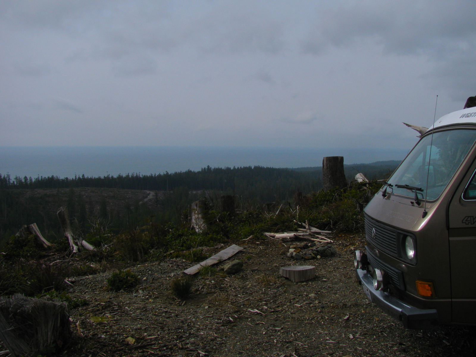
Wasn’t too bad, sunshine and a nice view.

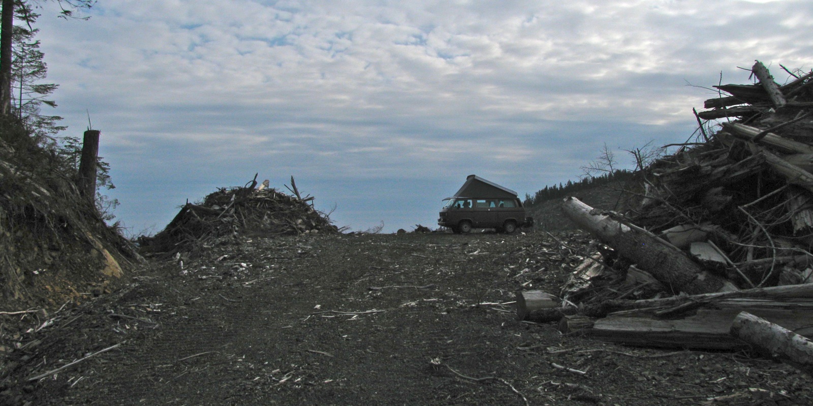
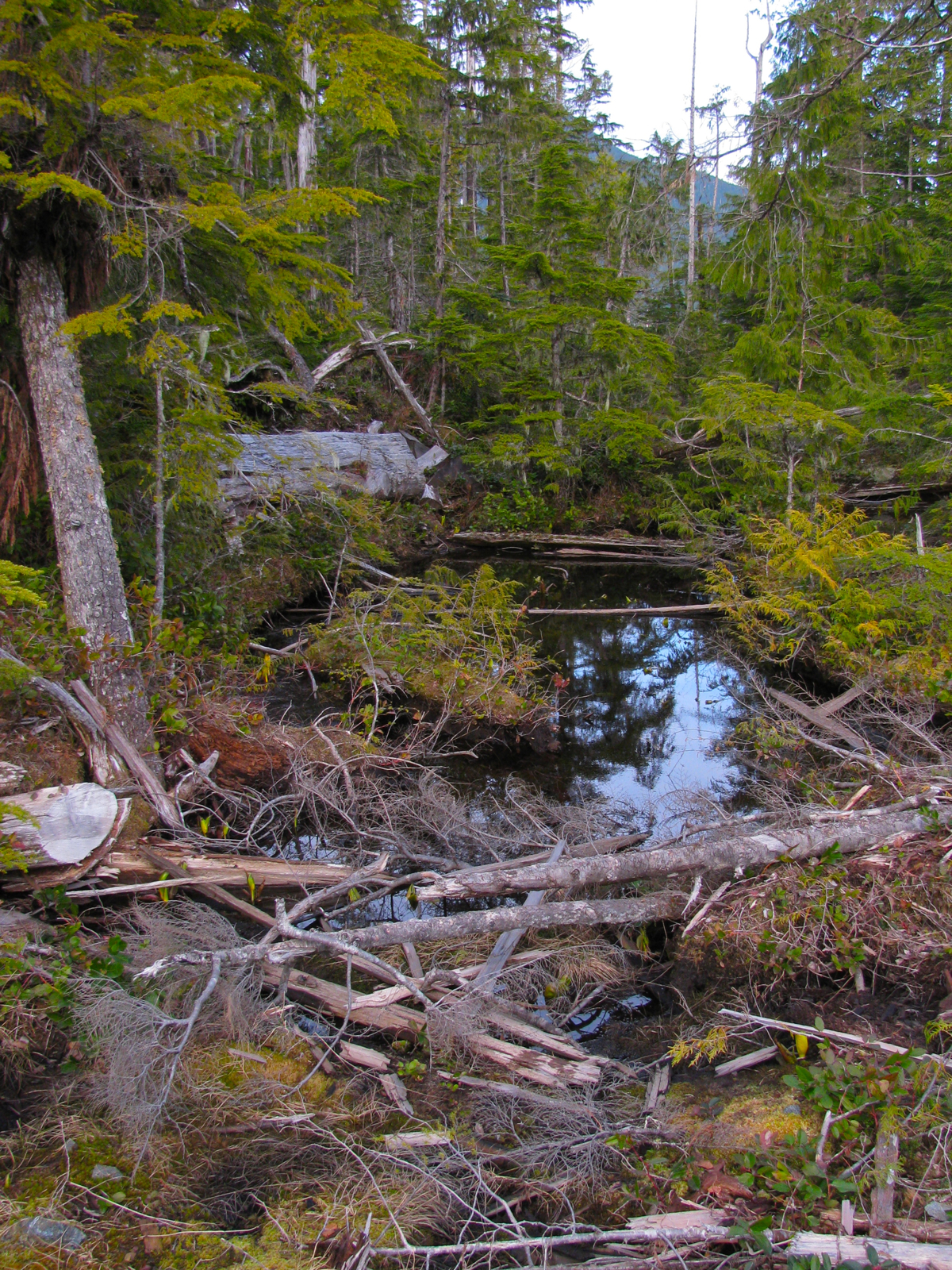
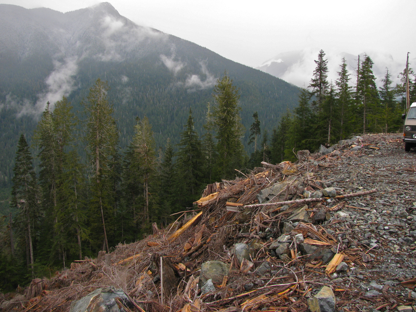
Walked down the road a ways and looked at the desolation after logging.

If you look closely you might be able to see the yellow shoots of Skunk Cabbage poking up at edge of the water.

Pretty little oasis amongst the logging.
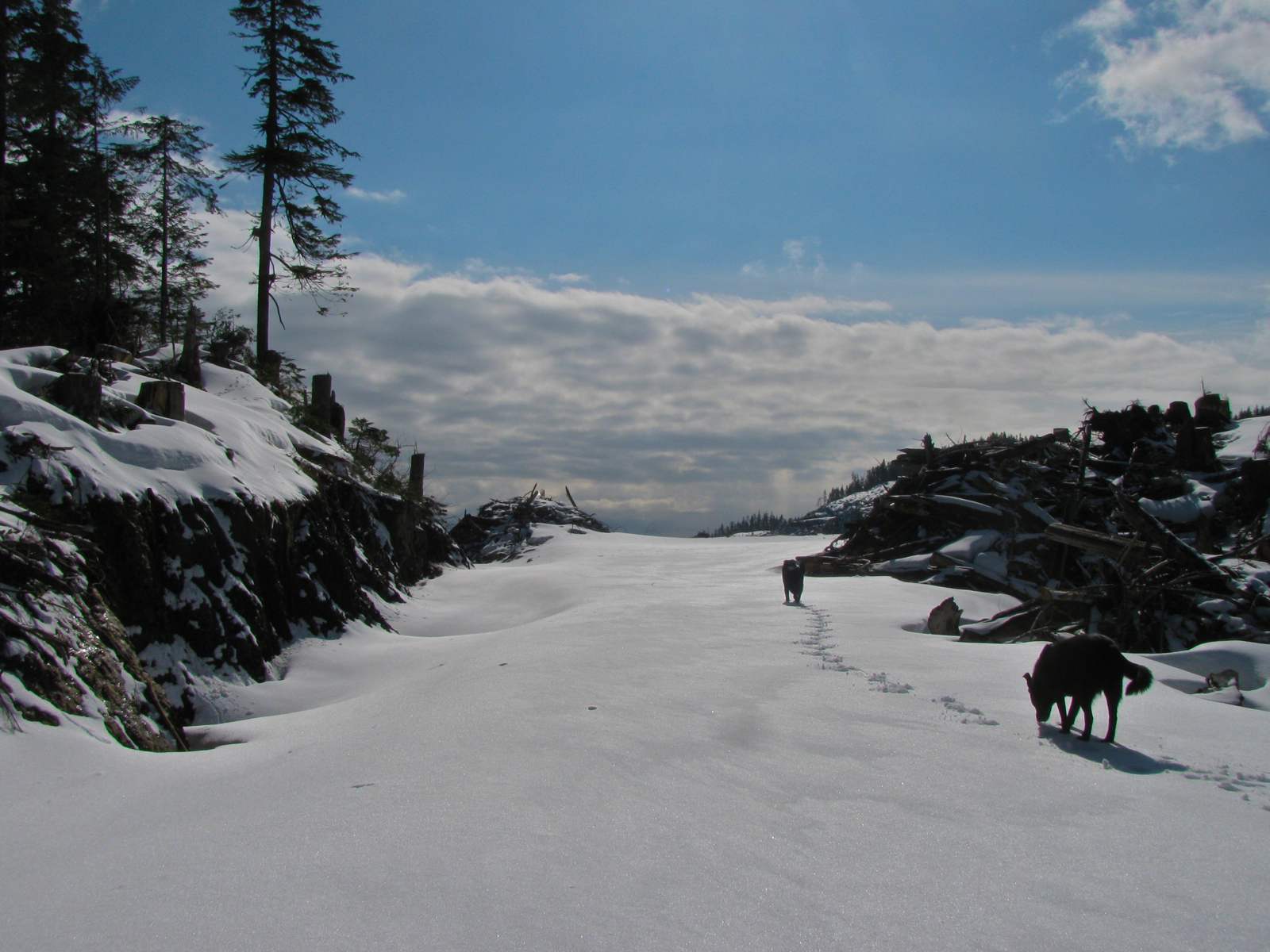
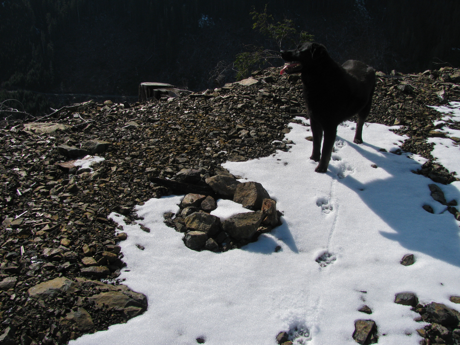
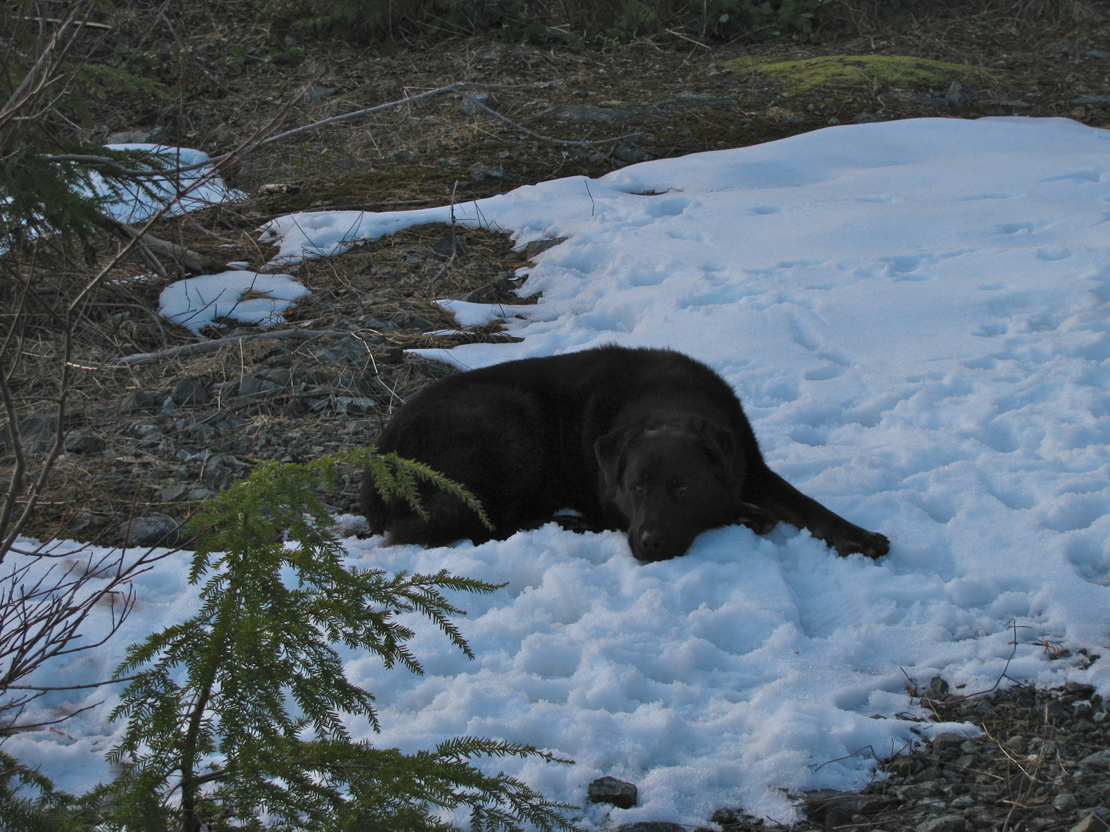
One of our dogs, loves the snow.
Cape Flattery, Olympic Peninsula, Wash. State.

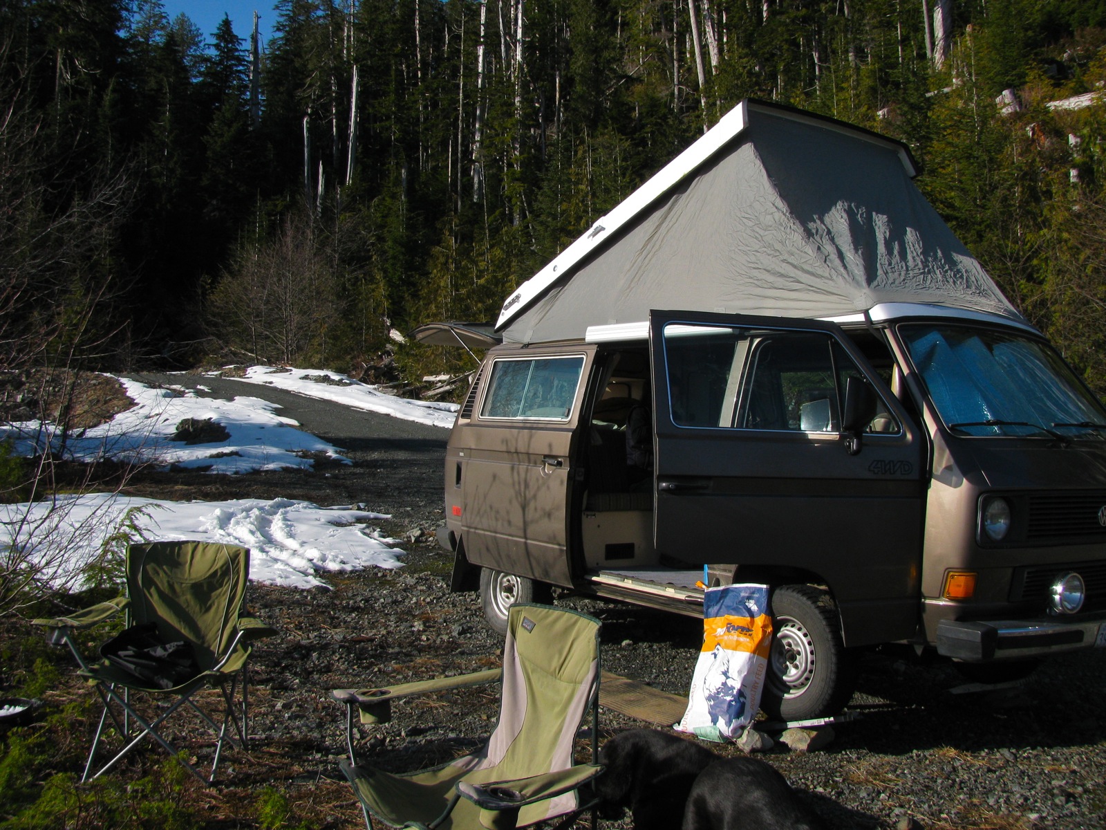
We had the Go-Westy rainfly up, and the Westy pop top insulation blanket installed inside. We also brought along the Olympian Plat Cat heater (not used when sleeping). The set up worked very well, and with the pop top vent cracked overnight, we have very little condensation on the windows in the morning. Must have had some sort of chimney effect going.

A little bit of snow falling next morning.

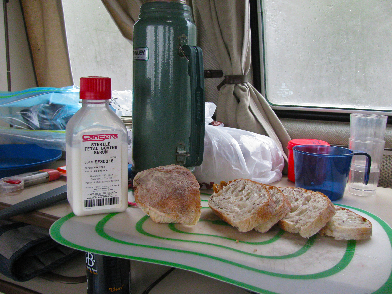
Breakfast, and the tell-tale sign that someone in the family is a Molecular Biologist.
The old “Excelsior” at work again.

The dogs taking up space.

Then off we drove to explore more of the area. The weather cleared a little, if it wasn’t for the wind it could almost be described as mild.
Nice little lake, second growth forest.
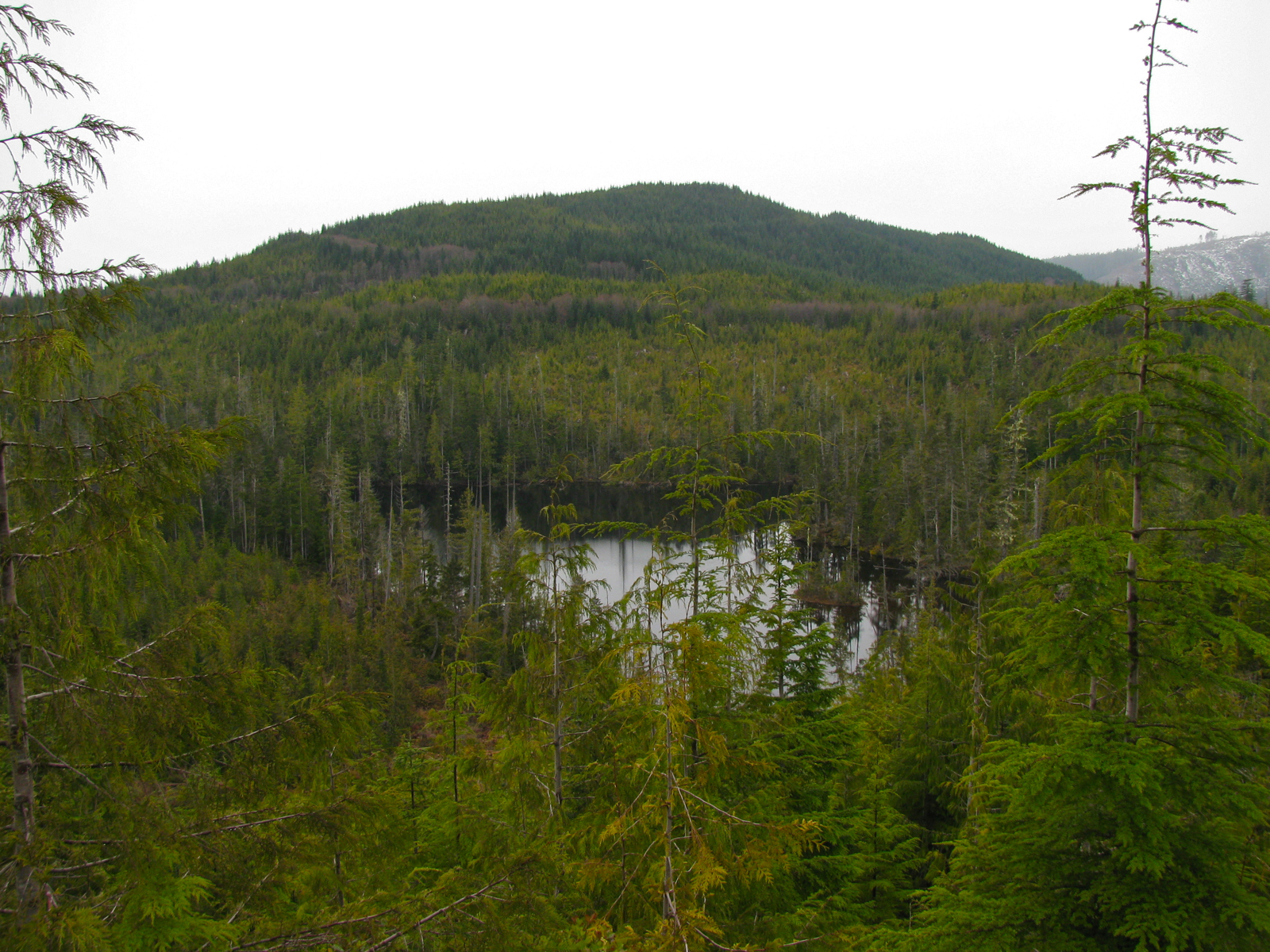
Edinburgh Mt. in the background, steep logging in the foreground.
And wouldn’t you know it, we even checked out the Camper Creek area campsite that we spent so much time at last summer.
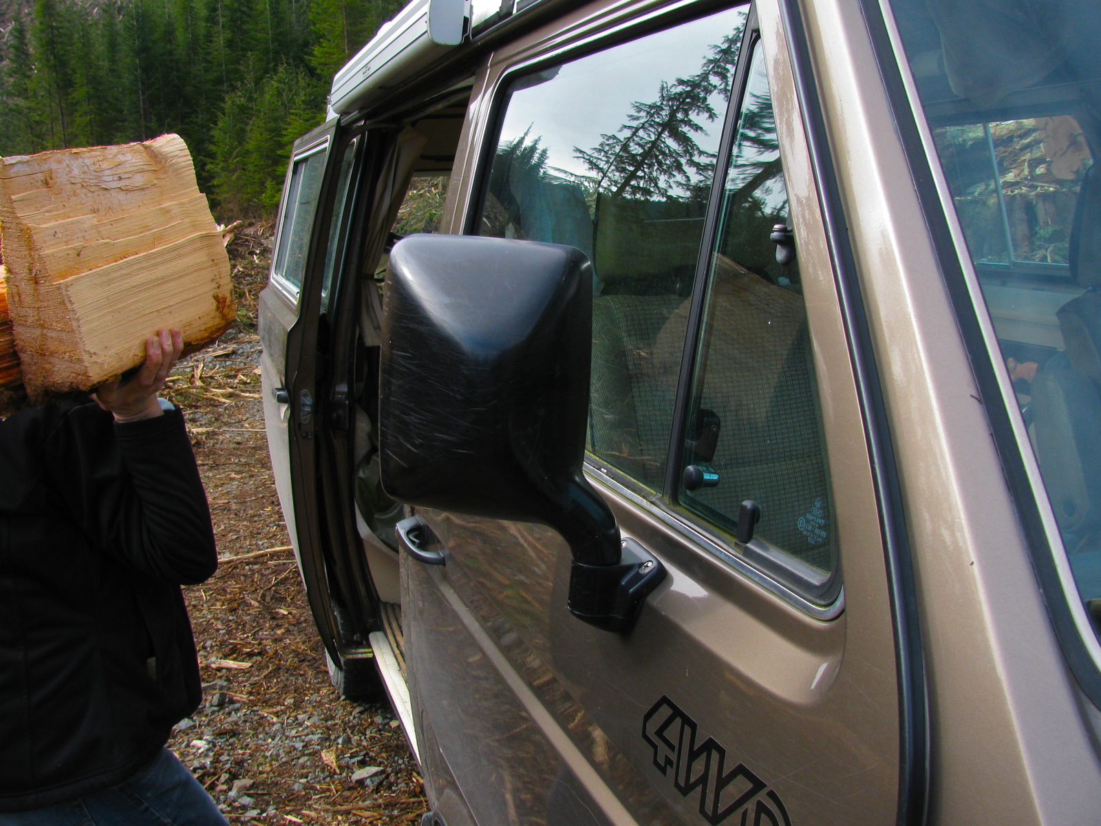
Ooh, kindling!

Notice how the mirrors take a bit of a lashing on these trips?
Came back home via Gordon River and Cowichan Lake (a round trip we have done many times before). Saw signs of kayakers along the Gordon – crazy folk who paddle down the canyons.
Vanagon – syncro front outer cv joint protection plate
Posted by albell in syncro, vanagon, vanagon mods on February 16, 2013
The story goes that VW introduced these protectors in 1990 for 14″ syncros with the rough road package, and on all 16″ syncros. Here is the English language bulletin.
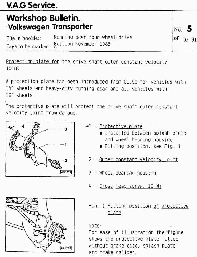
I wanted some. I worry about logging road debris catching on the front outer cv boot, and that boot is a pain to replace. You can buy them, one good source is Burley Motorsports, but seeing as there are plans for them on the internetubes I thought I’s have a go at making a set.
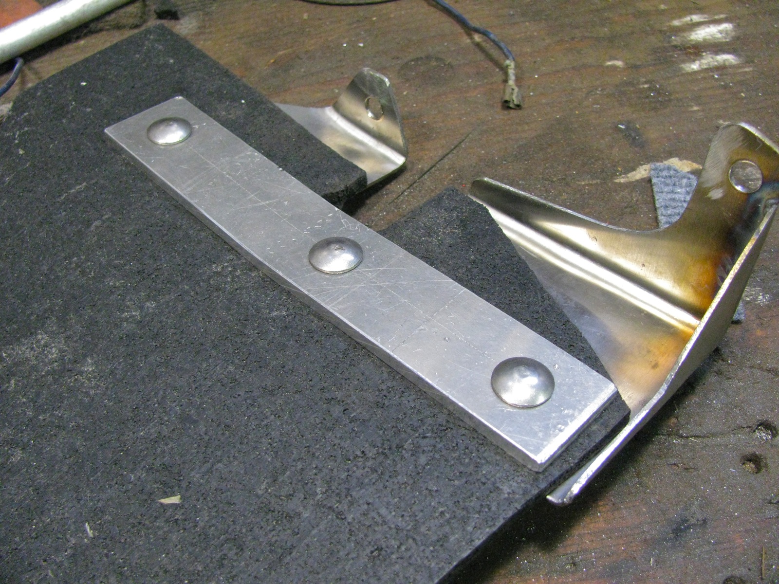
Here are the pdf’s of the plans I used: CV_protectors_bracket, CV_protectors_Rubber. I scrounged all of the material used, so my version differs slightly from the plans. First up are the metal parts. I had some scrap 14 gage stainless which is not quite as thick as speccified ( 1.6 mm vs 2.0 mm), and I glued a print-out of the plans to the metal and cut to shape.
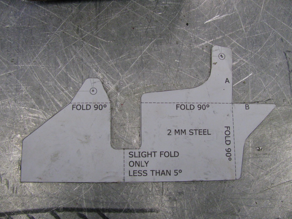
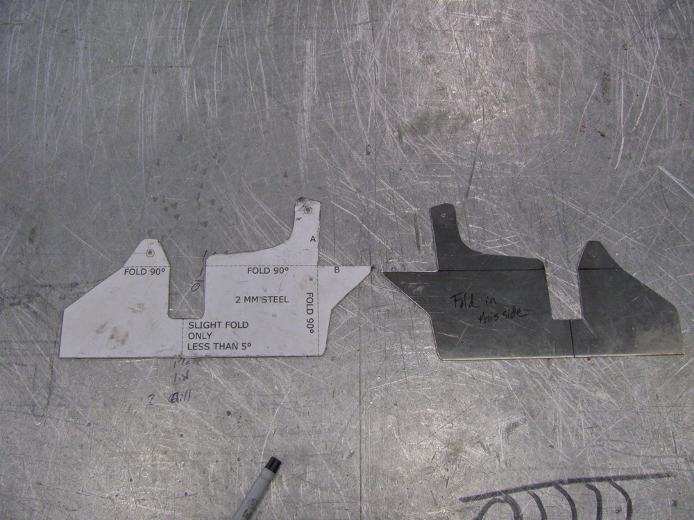
I bent the parts in a vise (that accounts for the less than crisp bends), then I made a hack-job of the tig welding. I need new glasses, well that is my current excuse for my poor welding.
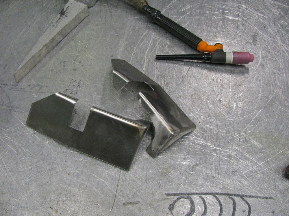
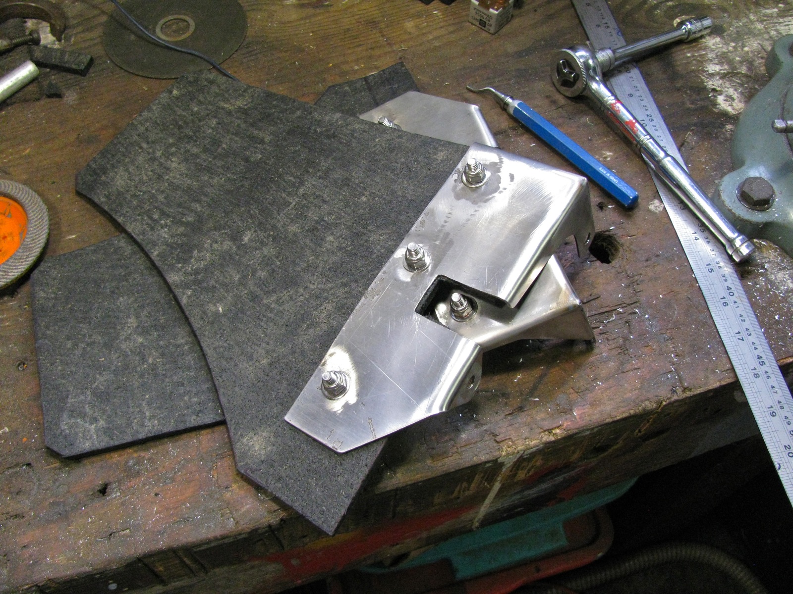
Next was the hunt for rubber. You’d think it would be easy to find some 1/4″ thick, fabric reinforced conveyor belting, wouldn’t you? I spent an hour looking then I used some 1/4″ rubber sheeting that my neighbour had. It is not the best stuff, it is like thin horse stall matting. You know, crumbled tires pressed together. I can always replace the rubber when I find the belting. Ok, enough mumbling, I cut the rubber and I cut some 1/8″ 6061 aluminum for the backing strip. I used 1/4″ – 20 ss carriage bolts (the square part of the bolt shank will dig into a 5/16″ hole drilled in the backing plate) and nylock nuts to hold all the parts together. Well all but one, I ran out of nylocks and had to use a split washer and plain nut.
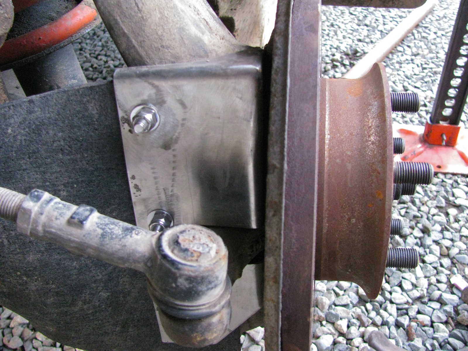
Okee-dokee, out to the van and installation. It is a bit of a pain, you have to remove the brake calipers and rotor to get to the backing plate. The same old but important safety warnings apply – van securely supported etc.
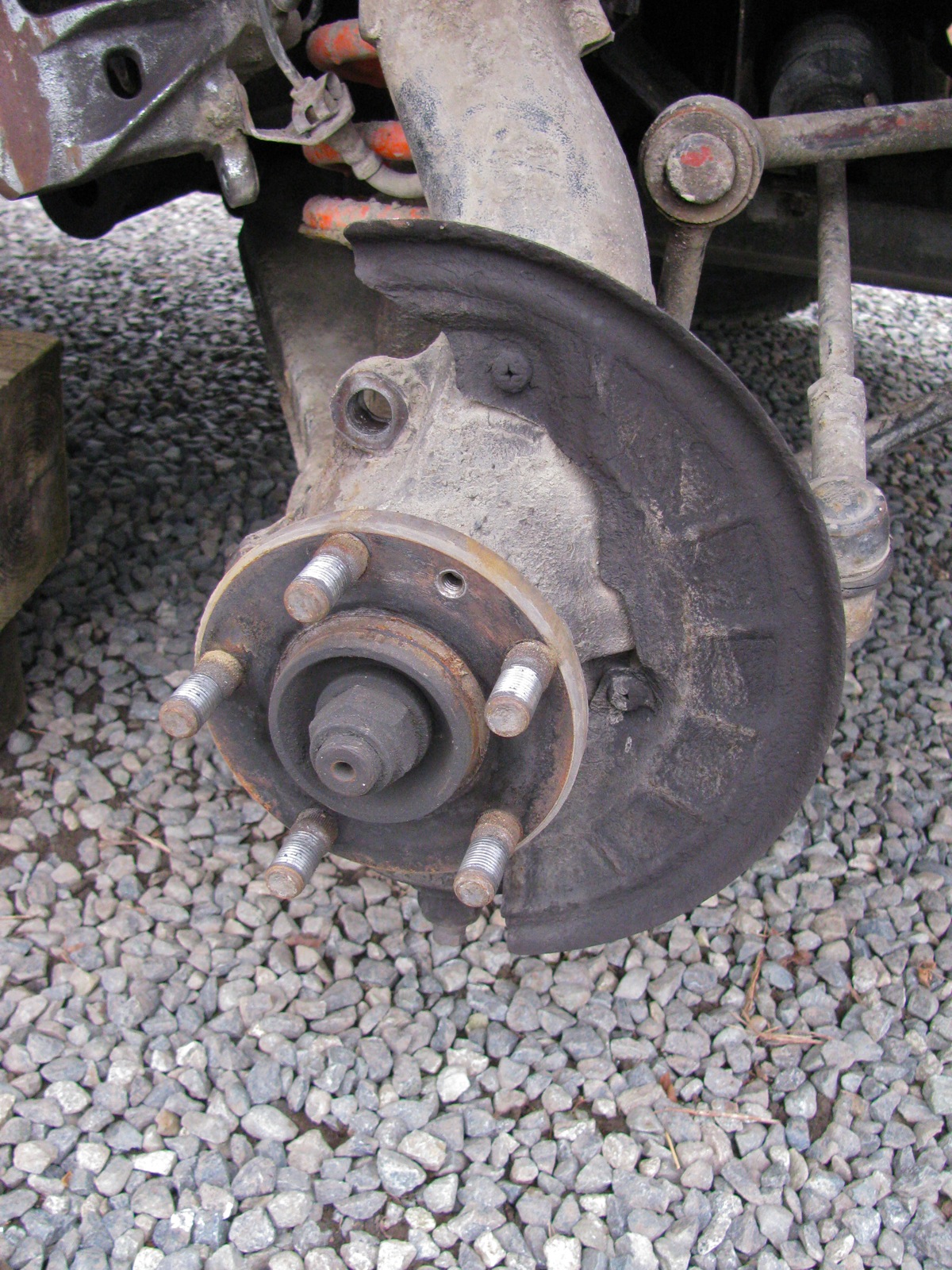
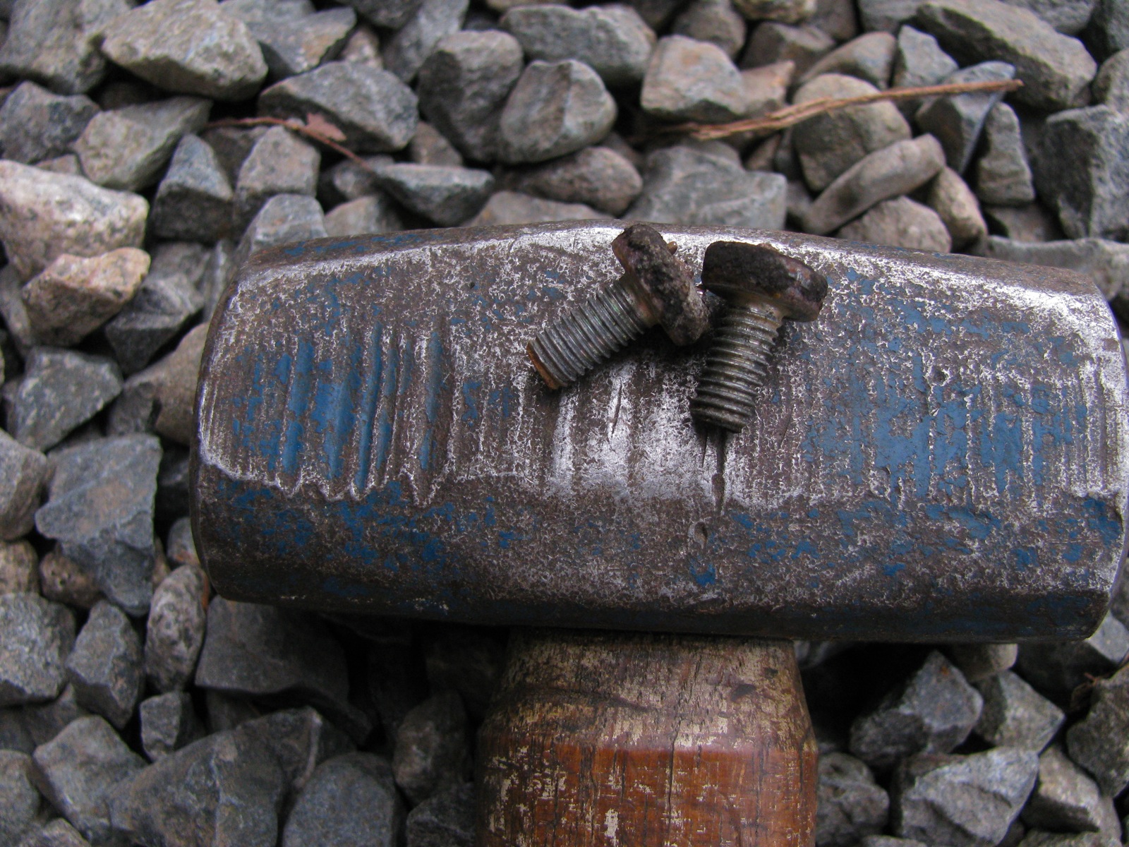
Two phillips headed screws holds the splash to the steering upright (or bearing housing, as VW calls it). They were fekkin tight, I doubt they had ever been removed. I had to use an impact driver, but even so I still managed to bugger up the screw heads a tad. I have said this before about my van, despite the ugly areas of body rust I have, all the fastenings (despite how tight they have been) are not rusted in.
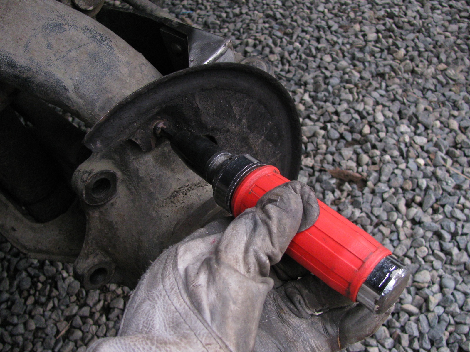
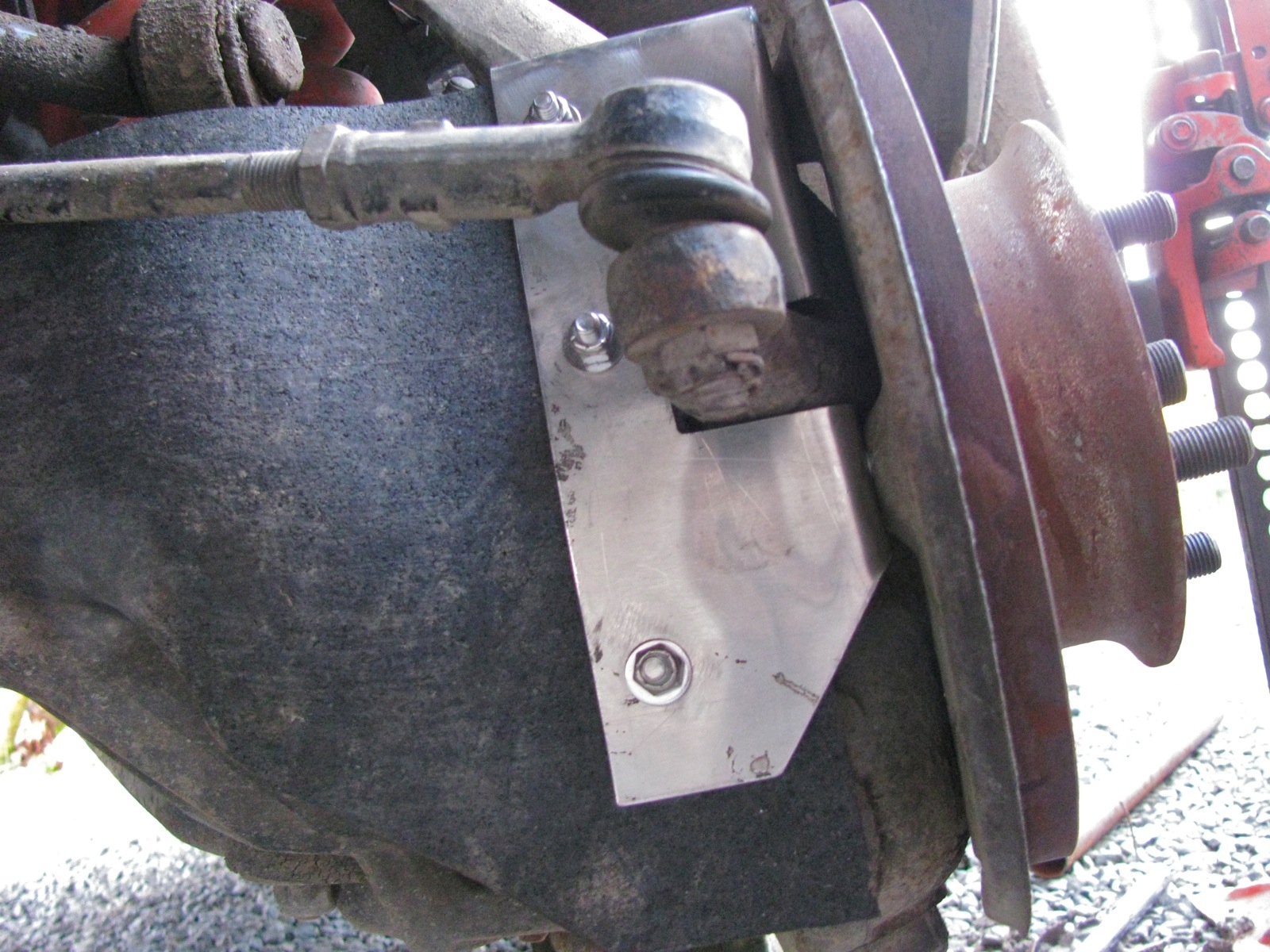
Once the splash plate is off the cv protector goes on and the splash plate reattached.
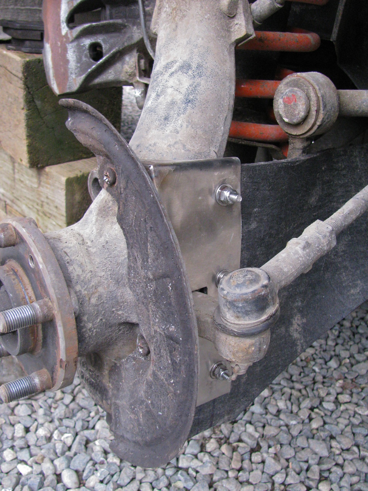
Another view.
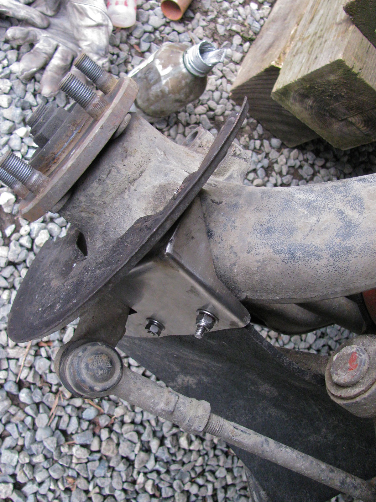
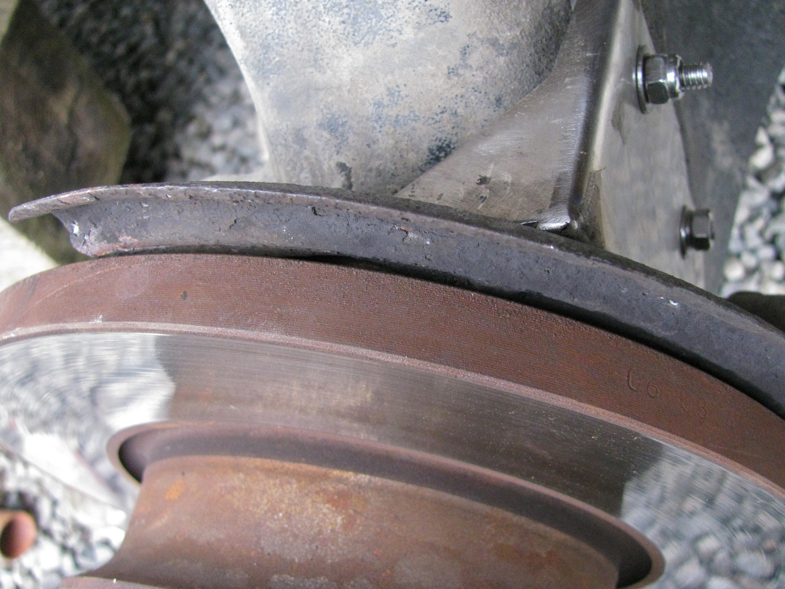
Brake rotor back on and the splash plate is now closer to the brake rotor by an amount equal to the thickness of the protection plate, but they do not touch.
The other side went a lot quicker.
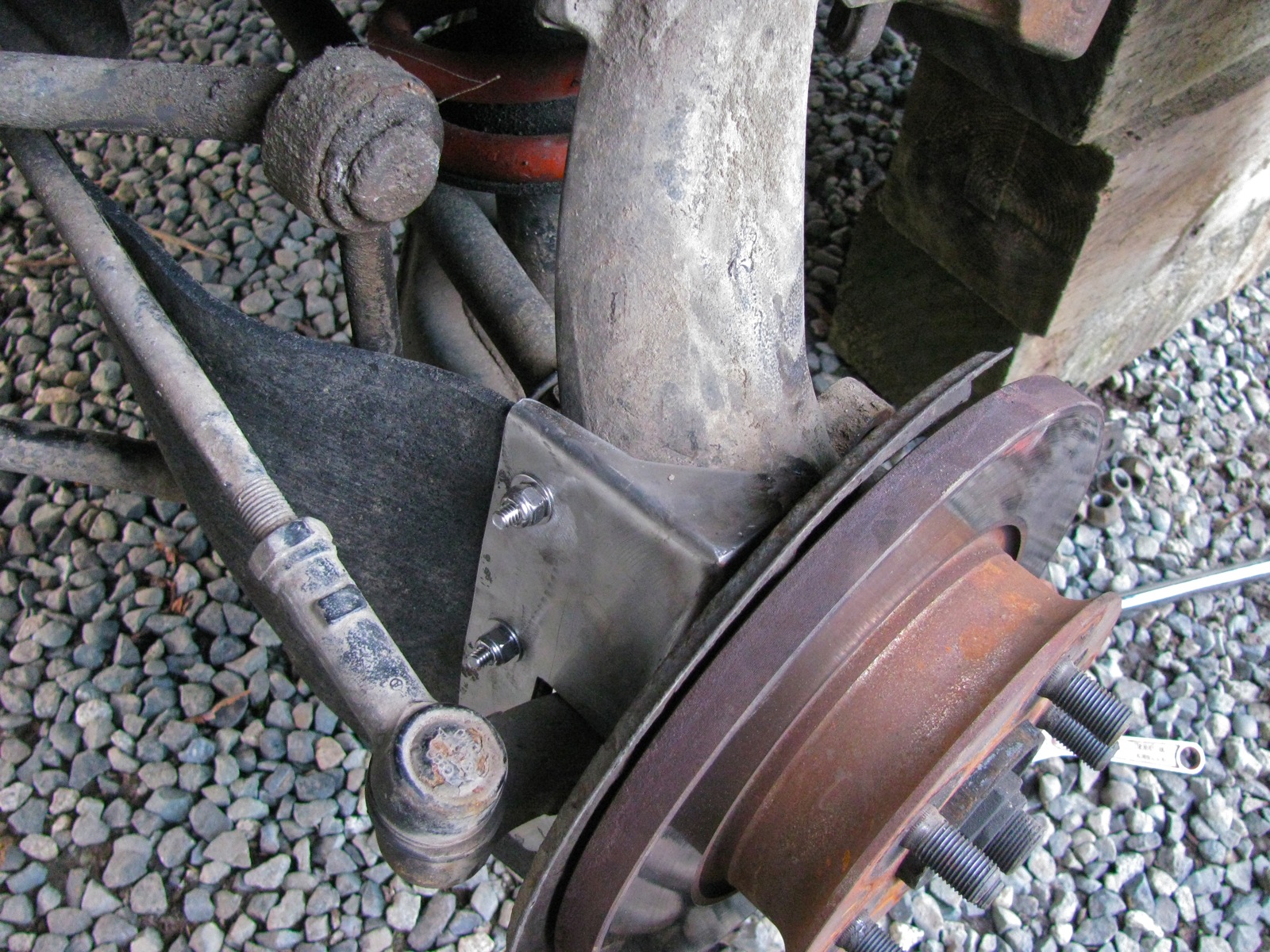
And with the van down on the ground.


I got more satisfaction from this little mod than seems normal. I don’t know why this should be. Perhaps because I do worry about catching a branch up there when I’m on logging roads. Or maybe it is because the project went without any real screw ups.
Addendum/clarifications:
Vanagon – home made muffler installed
Posted by albell in syncro, vanagon, vanagon mods on February 4, 2013
Finally got the muffler installed. Some pics of components are in this post. Since then I made some rough mounting brackets, copy of the stock brackets, but made from aluminum (3/8″ plate) with some 1/2″ studs welded onto the sides (for T-bolt clamps). I didn’t take any pics of the brackets, perhaps I forgot on purpose as my TIG welds were overheated and sloppy (I’m learning, slowly).
Here are the brackets before final shaping, mounted to a spare engine mount.

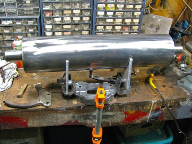
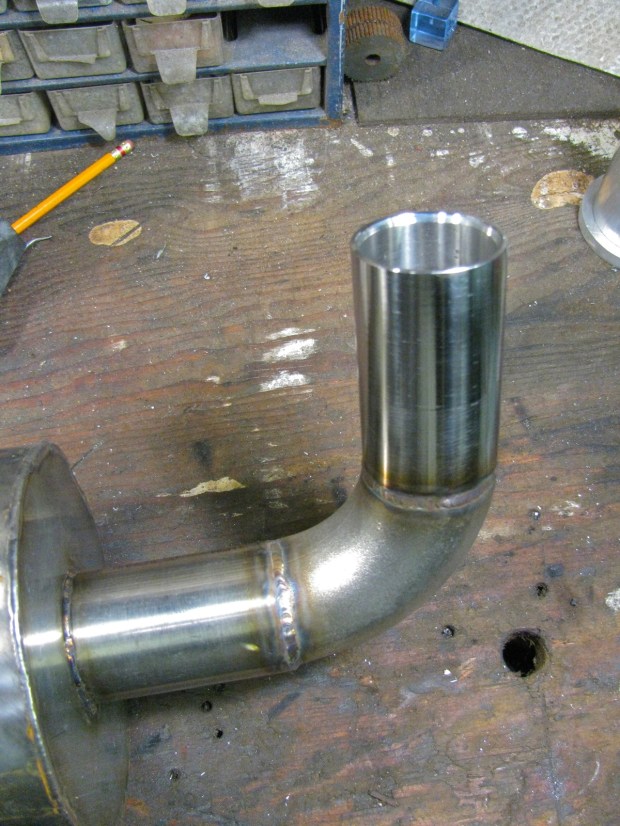
I copied the stock mounting brackets bolt holes and approximately the curves but adjusted to fit the 6″ diameter muffler. I also copied the relief curve on the bottom side of the brackets, allowance for the transverse connector exhaust pipe. A 90 degree SS elbow and a home made tail pipe was TIG welded on.
Install was pretty easy, brackets bolted right up to the engine carrier, ok, I admit, I didn’t get the muffler quite level. Once installed I realized I could have made thing a little differently to tuck the muffler up a bit higher. But all in all I’m pleased with how it hangs.
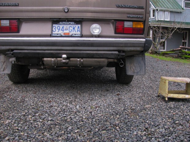

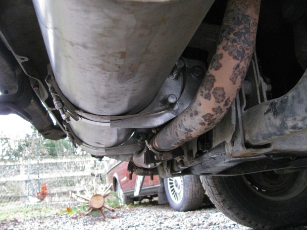
You can make out how the T-bolt clamps hang around the welded studs on the bracket. You might also make out the section of SS flex on the transverse exhaust pipe – a quick and dirty repair after cracking that pipe on a logging road trip.
And I made a little video to give you an idea of the sound. It is not as quiet as a stock muffler, but neither is it loud. Does have a throaty note.
I’ve always wanted (for some obscure reason) to make a muffler. And now I have, and by gum it worked. It’s the little things that get me through the day 🙂
Vanagon – Syncro propshaft angle measurements… again
Posted by albell in syncro, syncro specific repairs, vanagon on January 13, 2013
Warning: what follows is a very long-winded and tedious description of my further exploration of propshaft U-joint angles. Experienced and knowledgable readers, please, cut me some slack and refrain from face palming at my antics.
Being quite adept at re-inventing the wheel, I’m now re-inventing measuring propshaft angles. If you are a regular reader of this blog, and man it feels good to write that (evidence of my amusement with small things), you know I have spent some time exploring the flange angles of the transmission and front differential (my previous attempts, one, two, three.). I came cold to this subject, never having to deal with anything like this before, and Bentley has nothing to say about the matter. So perhaps I could be forgiven for my naive approach to the matter. Perhaps, but really no, I should have cut through the crap right away.
A little background
The transmission is connected to the front differential via a propshaft. On each end of the propshaft are U-joints (single cardan joints) that allow a little bit of misalignment between and movement of the transmission and the front differential. Now the problem with U-joints is that they do not transfer the rotational motion of the propshaft perfectly smoothly, ie. without pulsation, especially when the U-joint angles are greater than 3 or 4 degrees and also if the angles differ from each other more than 1 degree (more on those angles later). Most of you know this, and also about the correct phasing of the the U-joints on each end of the shaft, but I do recommend having a look at this document from Spicer that explains all:
Spicer info on driveshaft install, angles, vibrations, etc. (pdf).
And this Spicer document on measuring angles succinctly describes using Spicer’s angle finder doodad.
Spicer info on measuring angles
One subject not really covered well in that document is compound angles. That is when there is mis-alignment is in 2 planes, ie horizontal and vertical. I’ll go into that at the end of this post.
Over time I became dissatisfied with my last attempt at measuring flange angles with my laser tool. Don’t get me wrong, I think it is a pretty neat way of measuring the flange angles and it measures both in vertical and horizontal planes. But you need to have the propshaft removed.
After some email exchanges with J. Slider, I reconsidered the protractor/angle finder method of measuring flange angles. I wasn’t very happy with the results I got when I tried this method a while back. I was unable to get consistent results measuring the flange angles with my propshaft removed. It came down to getting the electronic angle finder positioned correctly on the transmission and front differential flanges. But Jon’s argument for the angle finder method convinced me to try again.
I was sidetracked by an idea of a false propshaft jig thing. I reasoned that if I could make a jig that mimicked the propshaft but was constructed so that flange angles could be more easily measured it would be a good thing. I even thought of making a false propshaft with fixed, *ideal* flange angles that I could use to adjust the transmission and front diff. mounts. I still think this would be a worthwhile tool to make for those folk who install propshafts in vanagons.
– This flurry of innovative thinking (ha!) coincided with me removing my propshaft and having it checked for balance by Royce at Island Torque Converter & Driveshaft. Royce is THE guy to take your propshaft to for repair/balancing. He does good work, prices are very reasonable, and he is willing to work with you in solving driveline issues. Local (Vancouver Island) phone # is 250 388 4248 –
Royce and I talked about the syncro propshaft and about making a shaft with Rzeppa type CV joints. That discussion is another story but when I was Googling around with the idea of Rzeppa joints on shaft I came across a document describing the install of a marine, Rzeppa jointed, short prop shaft. In that document (you can see it here) the use of jigs that I described above is detailed. Foiled again. Is it always to be thus? Are all my ideas “a day late and a dollar short”?
I took my propshaft to Royce around the 15th of December and got it back the next day. But with one thing and another I did not get the shaft re-installed in the van until the 9th of January. During that time, when I was not working, eating, drinking, Xmas shopping, sleeping, putting up then taking down Xmas trees, etc, etc, I was mulling over the propshaft jig idea.
Too much mulling, not enough action. So I ended up going back to the protractor/angle finder on the installed propshaft method. You’ve seen this before, and it is described in the Spicer document, I just added a very minor twist.
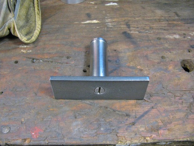
Home-made tool
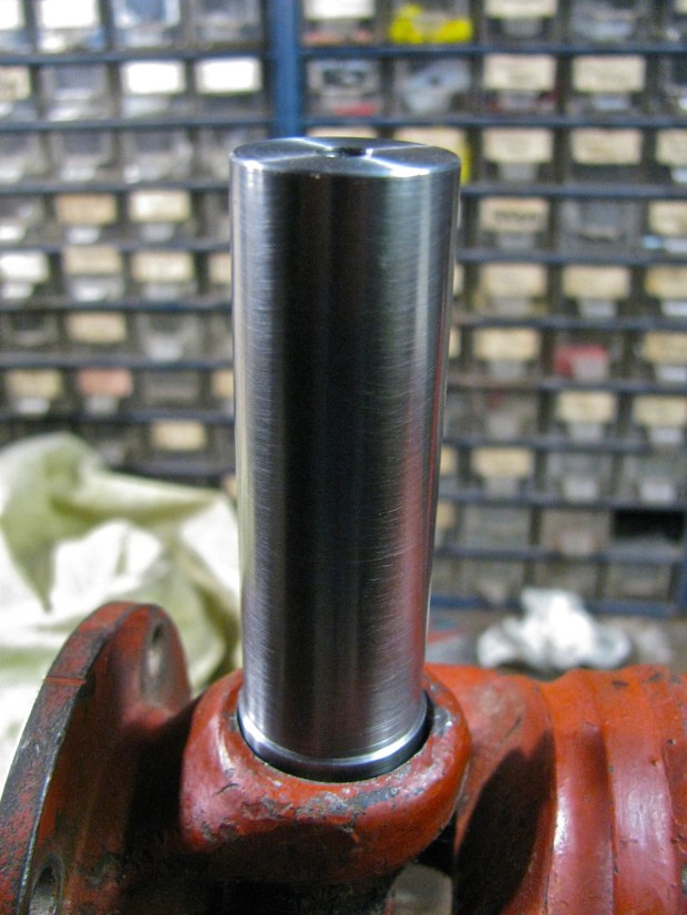
I mentioned at the beginning how I was never happy with the measuring propshaft angles with the angle finder because I could not get a good surface to place the gauge on. So I decided to do what others have done and use the ends of the U-joint bearing cup as the reference surface. That meant making a little tool.
A bit of scrap steel from some failed project.

Turned it down and machined a recess in one end to accept a rare earth magnet.
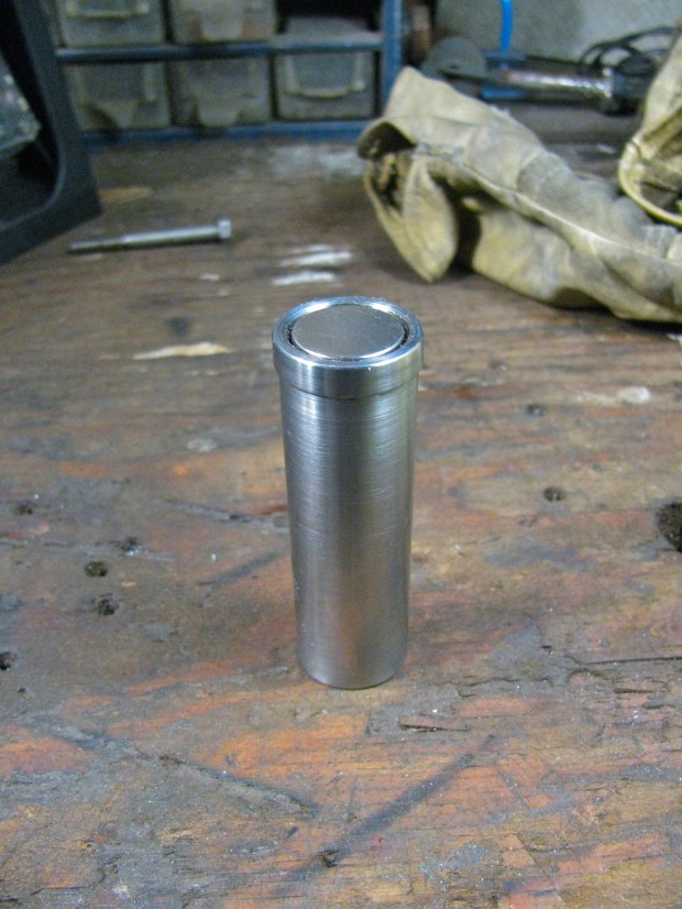
Fits in fine, held in firmly by magnetism and Locktite.
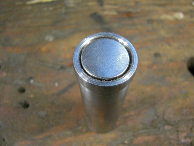
The magnet face is recessed from the rim of the tool by a gnat’s crotchet.

Here is my other propshaft, to be used for trial fitting. Big note here, ideally the circlip should be removed so that the tool can lie directly on bearing cup. But I reasoned that these circlips would be lying parallel to the bearing cups. Any dirt or damage to the circlips would screw things up.

Tool on the joint.
Angle finder on tool, held by magnets on side of angle finder. It looks like the angle finder is resting on flange, but it is not.

Angle finder on end of tool. I was not sure at this time which way would be better.

A bit of channel to provide a base to measure the propshaft angle.

Trying out the tool
Ok then, out to the van. First I had to install the re-balanced shaft (not the red one pictured above). I jacked up one side of van and supported on blocks. Wheels off the ground.

Small aside, I finally replaced the 1/2″ bolt used to hold the jack adapter onto the jack with a gated pin thing.

After the propshaft was installed (please note, I do insist on loosening the 3 bolts that go through the rubber mounts on the front diff. when I am installing/removing the shaft) I took the van off the blocks, released the parking brake and chocks, then crawled under to have a go at measuring angles. First I moved the van back and forth so that a bearing cup on the U-joint yoke that is attached to the flange was pointing directly down. I gave it a bit of a scrub then attached the tool.

See how the angle finder is a little askew on the shaft of the tool? This affects the angle measurement. It was hard to get the angle finder aligned true to the shaft when I was scrooched up under the van. Would have been much easier if the van was on a lift. But I persisted, went on to measure the propshaft angle.

And see how I do not have the angle finder aligned along the channel? It is askew too, and this affect the readinghh. And then on to the front diff. end of shaft.
Repeated the procedure a few times.

A bit better alignment on channel.
Again on the front.

And on the rear.

But I was not happy with the procedure, I was not sure of confident of the accuracy of the readings.
V-block modification and engine carrier adjustment
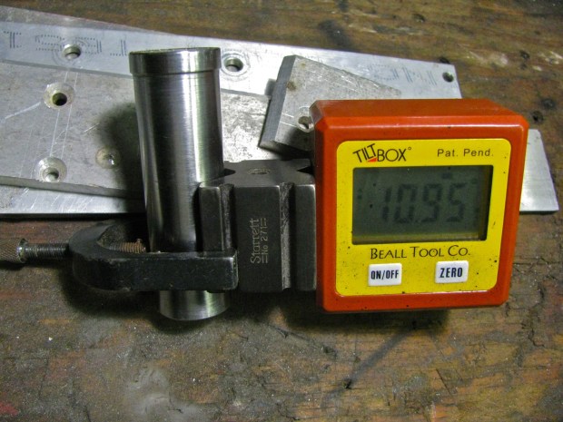
I tried a nice little Starrett V-block on the tool. I thought it might help me to keep the angle finder aligned along the long axis of the tool.
I was running out of afternoon and I wanted to try something more. I knew from previous measuring that the transmission flange pointed down more than the front diff flange. I wanted to reduce that angle, but I also new that there really is no easy way to do that. The transmission mounts towards the front of the transmission are really awkward to get at and fiddle with (especially when you don’t have a lift), so that leaves the engine mounts at the rear. But the arrangement/relative placements of the mounts means that it takes a fair bit of movement at the engine mount to effect a little movement at the transmission flange. Perhaps these data from R. Jones illustrates this (front diff. data included).
“4) I measured the distance between the flanges and the
mounting points, tranny and front diff, and worked the ratios.
Using washers, here’s what one can do:
a) raise front mount, front diff, lower flange.
1 unit raising gets 0.83 units lowering the flange.
b) raise rear mounts, front diff, raise flange.
1 unit raising gets 1.2 units at the flange.
This is the wrong way however.
c) lower tranny at front mounts, lowering flange.
1 unit at mount gets 1.25 units at flange.
Again, this is the wrong direction.
d) lower engine at carrier attachment to frame,
raise flange. 1 unit at engine gets 0.25 units
at flange. Hardly worth it.”
I wanted to try “d”. So I supported the engine carrier (“moustache bar”) with a jack and removed the 2 bolts, each side, that hold the bar to the van frame. I had no time to record flange angles vs. amount of lowering of rear carrier, and I decided to try 5/16″ as the distance lowered. Handy number, I had some 5/16″ aluminum plate scrap on hand. On the top side of the flange on the van body that the carrier mounts to there is a steel backing plate. I used that plate to lay out the bolts holes in the aluminum spacer.

Holes drilled.
And spacer inserted. I used longer bolts. Damn mudflap mounting strut interfered.

Maybe you can tell, the light was fading fast. I got back under and measured angles, using the V-block innovation.
Transmission flange angle.

Front diff. flange angle.

By now it was dark and I was cold. I left things as they as far as I got to: rear engine mount dropped by 5/16″.
It now occurs to me that I have not mentioned another little thing I did (a year ago) to resolve flange angle difference – I removed the topmost metal washers of the two rearmost mounts of the front diff. This did drop the flange of the front diff. a bit – I reasoned back then, that if I could not reduce the flange angle of the transmission the I would increase the flange angle of the front diff. I hoped that matching the flange angles did more to reduce vibrations than trying to get both flange angles below 4 degrees. I’ll clear this up at the end, I know this story is getting very muddy right now.
Road test
Okee dokee, I drove the van for the next couple of days. Felt pretty smooth, my 50-60 kph minor vibe has gone. I do have the very, very slightest vibration especially when accelerating, at around 40-45 kph. But I noticed this when the propshaft was removed so I am discounting that it has anything to do with the shaft.
I was pretty happy with this. I’d say that the re-balanced shaft is sweet.
Further modification to the tool
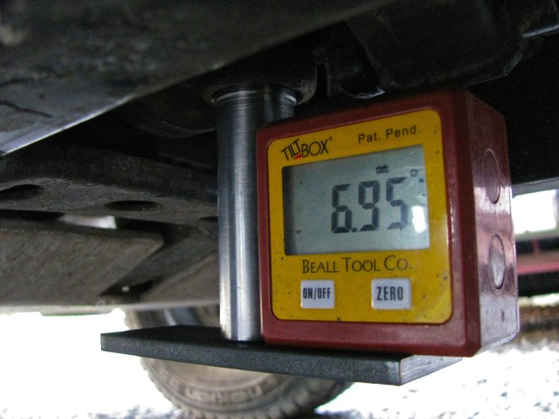
But I still wanted to measure the flange angles with somewhat more confidence. I cut a chunk of 1.5″ X 0.25″ hot rolled flat stock, drilled a hole, and screwed it (1/4 “- 20) to the end of the little tool. I checked it for square, was good. Now I had a better reference surface to place the angle finder against, and I could line up the long axis of the plate with the propshaft.
Here it is on the transmission end of the shaft. It is much easier now to use the angle finder to determine that the tool is pointing straight down, and the plate can be lined up fore and aft with the propshaft. Those two things are important in measuring the true angle of the flange. Remember, the tool is on the bearing cup in the flange yoke of the U-joint. That means it projects the angle that the transmission flange is making with respect to the propshaft.

One way of doing it. The angle finder was inline with the bottom plate of the tool. This was not a recorded measurement, I had not adjusted propshaft so that tool is pointing straight down.

I found that having the angle finder in this position was the best. The magnets in the angle finder held it to the vertical shaft, but still allowed it to be aligned to the bottom plate.
A another measurement (using the channel) of the propshaft angle.
And a good measurement of the front diff flange angle.

Results
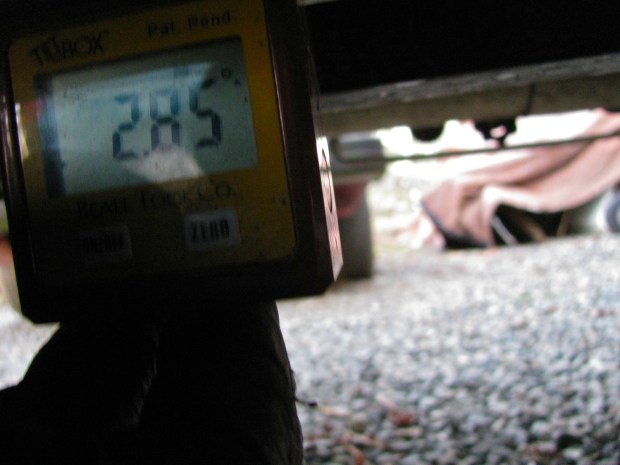
Ok, I was getting more consistent measurements, now to look at some of the data. Remember, we are measuring relative angles here, not absolute angles. For example, the propshaft could be pointing down towards the front at 1.30 degrees, or at 2.85 degrees depending (apart from measuring errors) on the level of the van (ie just exactly where it was parked in my driveway). The sketch below summarizes my results. The top cartoon represents the situation right after I installed the propshaft. Let’s go over it, bit by bit.
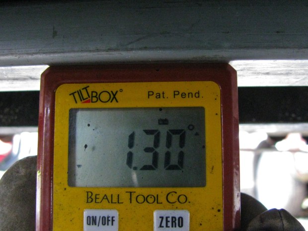
The transmission flange (and the transmission and engine) is pointing down towards the front of the van at 5.5o degrees. The propshaft is also pointing down in the same direction, but only at 1.30 degrees. If we subtract the propshaft angle from the transmission flange angle we will find that U-joint operating angle, and it is 4.20 degrees. Remember: if the angles are in the same direction then subtract the smaller angle from the larger angle to find the joint operating angle.
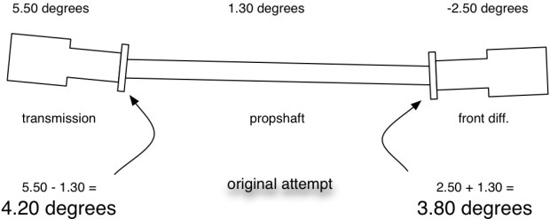
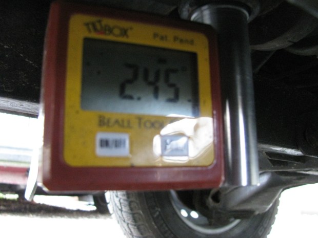
At the other end the front diff. is pointing down towards the rear of the vehicle, in the opposite direction of the propshaft angle. I added a negative sign to that measurement to remind me of its different direction. So in this situation the absolute value of the front diff. measured angle, -2.50 degrees, is added to the propshaft angle of 1.30 degrees. Result is a 3.80 degree joint operating angle. Remember: if the angles are in opposite directions then add the absolute values of the two angles to find the joint operating angle.
As clumsy as those two paragraphs are, I hope you get the idea of how the operating angles are arrived at. Of course with an electronic angle finder I could have zeroed on the propshaft angle and read the working angles directly. But I thought it would be clearer to me and to you if I did it explicitly.
Now the measurements after I installed the 5/16″ (8 mm) shim back at the engine carrier.
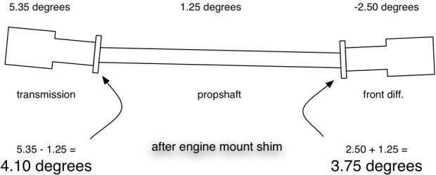
And finally, the same set up but this time more accurately measured (bottom plate added to my home-made tool).

I am fairly confident in this last measurement. Even if it is not perfect, I am sure the two flange angles are within 0.2 degrees of each other, though I do wish that the operating angles were less.
Compound angles
At the beginning of this post I said I was going to discuss compound angles, so here we go. The above sketches show angles in a vertical plane, but you can imagine that the same thing could be going on if you could look down from above. The transmission and front diff. could be laterally mis-aligned. What is interesting, is the combined effect of both lateral and vertical misalignment. The Aquadrive document I linked to previously has some good information on compound angles.
The accurate formula for calculating the compound angle is:

Lovely stuff eh? Shall we do an example? (and please God, let me do the math correctly).
Let’s say we have a vertical flange angle (ie the kind we have been measuring ) of 4.1 degrees. And let’s say the lateral angle is 1.0 degrees. First step is to find the tangents of those angles.
tan 4.1 = 0.0716808913
tan 1.0 = 0.0174550649
we square both of these numbers and add them together:
(0.0716808913)^2 + (0.0174550649)^2
= 0.0051381502 + 3.0467929066e-4
= 0.0054428295
then we take the square root of that number and we get:
0.0737755345
now we take the arctan (inverse tangent) of that number to find the answer, our compound angle:
compound angle = arctan (0.0737755345)
compound angle = 4.22 degrees
(Another example – 4 degree vertical angle and a 2 degree lateral angle, then the effective compound angle would be 4.47 degrees)
Not much of a difference, 4.22 degree compound angle compared to 4.10 degree vertical angle. So should we worry about lateral misalignment? Well, in the stock set up there is some room to laterally adjust both the transmission and the front diff. The old trick of leaving the front diff. mount bolts a little loose after installing the propshaft, then driving the van for a few miles before tightening those bolts, probably serves to reduce or eliminate lateral mis-alignment. But with vans that have non-stock engines/engine carriers installed, then there is a very good chance of having the engine and transmission laterally askew enough for that trick not to be enough.
Conclusions:
- no matter what you read or hear, in the vanagon syncro the propshaft operating angles should be 4 degrees or less (but not zero degrees). Ideally they should be less than 3 degrees. Unfortunately there is no easy way to adjust the front diff and transmission vertical flange angles to achieve this. On vans with engine conversions and modified engine carriers, careful attention MUST be paid to the transmission angle.
- U-joint operating angles should be the same or within 0.2 degrees of each other.
- measuring the angles can be done fairly accurately with home-made tools. A smart phone with an inclinometer app could be used instead of my little electronic angle finder. But some sort of adapter between the joint and the phone must be used to ensure accurate and consistent readings.
- lateral misalignment of the transmission and resulting compound angles are very important to check and deal with if a non-stock engine has been installed. Remember that the angles combine and result in an effective angle greater than any one of the individual angles.
- Your man on Vancouver Island for propshaft balancing is Royce at Island Torque Converter & Driveshaft. Phone # 250 388 4248
Vanagon – my auxiliary battery wiring
Posted by albell in syncro, vanagon, vanagon mods on January 6, 2013
I only had a little time to do any Vanagon stuff over the break, a couple of things were dealt with, I’ll post it up over the next couple of days.
First up is my auxiliary battery install. It has been working fine for the last couple of years, but recently I have noticed (with the help of the Doc Wattson, blog post here) a couple of disturbing things. First one is, and I have not figured this out, is a peak amp reading of 20 – 30 Amps. I never see it happening, even with mucking around with stereo settings while I look at meter. And I don’t have a circuit in my aux. battery set up with a fuse larger than 20 A. I do suspect the stereo amplifier, but it must be a very brief transient spike in current draw.
The second thing is a chronically undercharged aux battery. I suspected, and suspicions confirmed by the Doc Wattson, that the Blue Seas ACR (a now discontinued model, CL series BatteryLink, p/n 7600) I use to switch between the main/starting battery and the aux battery was not combining the batteries when it should have been. The ACR ( automatic charging relay) does have indicator lights on it, but the unit lives under the driver’s seat.
The ACR has provision for wiring in a remote located LED that lights up when the ACR combines both batteries. So I set about adding that and at the same time I would go over connections and ACR settings. I suppose a picture to give you the lay of the land would be a good idea. I admit, it is a bit of a dog’s breakfast. Working around clockwise the stereo amp is on upper left (old Alphasonik that came with van), then auxiliary fuse panel, to the right and up is the Doc Wattson meter, below that is the 31 A/hr AGM auxiliary battery, Schumacher trickle charger, then finally the Blue Seas ACR.

Yeah, clear as mud. Fine then, I’ll make a quick sketch.

Edit: link to how I connected to main fuse panel S3 circuit from aux. fuse panel.
Under the cover of the auxiliary fuse panel. Its is from an early 2000’s Golf/New Beetle and was installed right by the battery. Useful little thing, I’ve had this one for about 11 years (used it on my old ’82 westy).

Ok, back to the ACR trouble shooting. I ran a pair of wires up to the dash, and mounted a blue LED indicator light in a rather temporary way under the lip of the dash. The light is from Princess Auto, made to fit a 1/2″ hole and has resistor built in, much easier to buy than to fiddle around making one up – ha, I must be getting old. Disregard switch and knob to the left of the light, has nothing to do with this job.

Testing connections, oh, brighter than I imagined. Looks like it is going to provide some mood lighting.

Ok, so I have the indicator light installed which will let me know when the ACR has combined the starting and the auxiliary batteries, and I have gone over wiring connections and ACR settings. First time I drove the van all went well, the LED came on after about a minute (this is as it should). The second time I drove the van the light did not come on, the ACR did not combine the batteries. What is going on? I moved the driver’s seat and looked at the ACR – well blow me down – the over voltage light was on.
I should explain, the ACR has 2 user adjustable settings. One is the voltage at which the batteries combine or un-combine. I have it set at 12.5 V and that means when the ACR senses that the voltage on the main (starting) battery drops below 12.5 V it will un-combine the batteries. And when the voltage measured on the main battery is above 12.5 V, than the batteries are combined (there is a time delay built in to weed out voltage spikes).
The second user adjustable parameter is the over voltage setting. The manual states:
“The OVERVOLTAGE potentiometer is used to adjust the voltage at which the CL-Series BatteryLinkTM ACR switch opens in response to high voltage. This is a protection feature when one battery needs to be charged at a lower voltage than the other. It also protects the second battery bank in the event of an overvoltage condition produced by the alternator.”
The van is still running and I glance over at the Doc Wattson meter and notice that it reads 14.94 V. So that’s it, the ACR has un-combined the batteries because of a too-high alternator voltage. I had the over voltage set to 14.85 V, and that seemed fine as I had adjusted my alternator to 14.5 V (yes, I have an adjustable reg. on the alternator), but now the alternator was putting out 14.94 V. It is strange, I didn’t see that high a voltage any time before.
I re-adjusted the voltage reg back down to 14.5, and the over voltage light went off and the batteries were combined.
Edit: Dennis H. advised me to re-adjust the voltage reg down to a max of 14.2 V. I think I will follow his advice.
So was this the ironic reason my aux battery was being undercharged – alternator voltage too high? I have to admit that I’m not 100% confident in the adjustable volt reg. I put in the alternator. I had one flake out on me on my old ’82, and now this one might be showing signs of “wear”
Finally (thank god, what a long winded and dull post), I still have that old Halon fire extinguisher I had in the ’82.

Vanagon – Syncro propshaft bushing – 6 month update
Posted by albell in syncro, syncro specific repairs, vanagon on December 15, 2012
Today, after the latest storm blew over and rain stopped, I got under the van and pulled the propshaft. “Again?” I hear you say, yes again. This time prompted by a few things:
1. I still have the slightest bit of propshaft vibe around 55-60 kph
2: J. Slider and I have been having an email correspondence discussing measuring flange angles on shaft. I want to re-do my measurements after the exchange of ideas we had.
3. I have a jig in mind to set flange angles.
So I pulled the bugger and it will be taken to driveline guy to check balance. So seeing as I have it off, I thought I’d check how the internal Delrin bushings I made back in June are holding up (the original posts describing how I made them, part one and part two). Well, the fit of the shaft in the bushings is as tight as it was when first installed. I tried to get some pics, in one of them, you can make out the split bushing still intact at the end of the bore. I have to admit that I worried that the split bushing wouldn’t last, I’m pleased that the Delrin held up.


Vanagon – muffler update
Posted by albell in metal working, metalworking, syncro, vanagon, vanagon mods on December 13, 2012
I got the final end cap welded on today, not the neatest tig weld due to my poor cutting of that end of the can. No filler was used in the weld, just flowing the parent material. I gave the muffler a quick once over with a cup wire brush on the angle grinder. I think this is as far as I am going with the finish, I don’t see myself holding the thing up to the buffing wheel for a couple of hours.
The pics show the muffler sitting on some aluminum off cuts ( I have access to a lot of interesting shapes in various thicknesses of aluminum, remnants from water jet cutting of work parts). These scrap bits had curves to match the radius of the muffler. The scrap is clamped to a spare engine mount casting so I can see how I need to move things and what metal to remove. I’m leaning towards the aluminum supports (yes David, there will be electrolysis where the ss and Al touch:)) with some T-bolt ss straps holding the muffler tight.


Vanagon – Fluid Film on underbody pics
I just took quick snaps but you get the idea. The entire underbody looks wet, and in some places you can see a beige coloured thicker layer of Fluid Film where i hesitated with the application. I did take some time to spray into the hollow frame members.
Vanagon – Fluid Film doesn’t taste that bad
I bought a gallon of Fluid Film, that lanolin based rust preventative, a few weeks ago and I am just in from spraying the underbody of the van with the stuff. I had a bit of difficulty with the applicator I used, it did not spray the as thickly as I’d would have liked. But I think the multiple passes did the job ok. Well I have to confess, I found another applicator during the day and did a re-spray just before dark. I’ll take pics of the results when there is more light, but meanwhile here are pics of the can and the first applicator used. BTW, the consistency of the Fluid Film is a tad thicker than good quality latex paint. And yes, despite my best intentions, I ended up with the stuff everywhere. But is does make your hands baby bottom soft.


Have a look at this, a drop of Fluid Film (one of many around the workshop now) that fell onto the top of the new jerry can. I consider the grinding dust to be evidence of my hard work, not of sloppy housekeeping. Note the creeping wet spot.

Vanagon – bent syncro bash plate
Or syncro bash plate bent, or bash plate syncro bent. I was under the van the other day patching up my rotten exhaust for the umpteenth time and I noticed this part of the stock skid rail/bash plate bent. Worryingly close to the engine and I don’t recall hitting the rear end *that* hard this summer.

Vanagon – front brake fandango
Posted by albell in syncro, syncro specific repairs, vanagon on September 19, 2012
I hope the story that follows will help someone be less stupid than I have been the last 2 days. No, that doesn’t sound right, no one would have been as dim as me notwithstanding.
Story starts with passengers complaining of squeaks from front left brake/wheel. Further development was noticing a clunk/rattle when going downhill on washboard/rough roads this last weekend. Noise seemed to be affected by brake application. Signs say examine front end and brakes. So I do that, could not find any loose or broken suspension components but did find that my brake pads were getting thin, and one pad on pass. side had a broken spring. So here is where I should have sat down and thought things through more. New pads are a good idea, but what about new rotors too? I did measure old rotors, they were within wear spec, so ADD boy here rushes out and buys some expensive Pagid pads and leaves rotors alone.

Quite a difference in thickness between old and new eh? Hint: that should have triggered a response in my brain other than “gee, look at the thickness difference”. Oh and another oversight, I mentioned that I measured the old rotor thickness, doing that I did note the ridges on the rotor (peripheral and internal) where the pads do not touch. I didn’t think that would be an issue, ha!

So I popped in the new pads. Bentley describes the procedure well, but did I do a careful reading? No, I didn’t. I removed both bolts from the caliper slider and removed slider to install pads. That is NOT how to do it. There are bold warnings not to re-use those slider bolts and the new pads came with just 2 new bolts (with pre-applied thread locker). I was puzzled by this, I thought I was shorted 2 bolts. So I used loctite and re-used the old bolts. This was both good and bad as you will see later. I finished pad replacement Monday evening and did not take van for test drive, yet another dumb-assed mistake. Next morning I had an important errand and as I drove out I noticed a rubbing/clicking noise from front right wheel. Bloody hell, drove back and popped that wheel to look. Rushed examination, pulled pads, noticed scoring on inside pad where it was hitting the un-worn area of rotor. Aha I thought, and beveled that part of pad a tad with stationary belt sander. Noise still there. Borrowed car and rushed out. I had the chance to drop by Autospiel that day and talk to Russ about this noise. I explained situation, he asked if I had checked that the rim, or balancing weights were not hitting caliper, I said no, I believed it was the pad on the un-worn part of rotor. Why don’t I listen and think? I decided to by a couple of new Brembo rotors from him (39 bucks a piece), and at same time, noticed them on the counter, a set of radius arm bushings (mine are old and worn out, I’ll post about replacement later, nothing to do with brake job). Got back home and set about rotor replacement.
This time, doing it right. First remove the pads. Undo lower bolt of caliper slider, in this pic I have 13 mm wrench on bolt and crescent wrench on flat of slider rod.


With that bolt out, the caliper body swings up and the pads exposed. Pull out pads.

Now those aneurism inducing 22 mm bolts (2) that hold caliper body to suspension upright. They are on tight (200 ft-lbs) and not much access for the lift deprived driveway “mechanic”. Shoot, forgot to state the usual warnings, ie support van SECURELY on jack stand/good wooden blocks during this procedure. You are really putting a lot of grunt into the van when loosening and tightening those bolts.


Ok, caliper off and hanging on breaker bar stuck in suspension. The slider part came off and is sitting to the right in this picture.

That hex socket bolt need to be removed, 5 or 6 mm? can’t recall.

Then the rotor should slide off the hub. Well, it started to but then hung up on something. At this point I really was not sure of anything, I consulted Bentley again, and again, finally used a puller.

I think it was this rust that was making the rotor difficult. Look at the state of it! What in the name of all that is holy was I thinking when I first decided to leave the rotors alone?

What it looks like with rotor off.

New and old.

New rotor on. I must say that it did give me a warm fuzzy feeling to look at it.

Caliper body re-installed and 22 mm bolts torqued back up to, ugghh, 200 ft-lbs. Pads installed, caliper slider swing back down into position and new bolt used in bottom position. You may find that you have to press in the brake piston to get the caliper to fit over new pads. I used a C-clamp to push piston in.

Other side done, wheels back on, tools put away, brow wiped. Ok, test drive…. rub, rub, rub. Son of a gun (or words to that effect), the noise is still there. Noise goes away when braking, that is a clue. On passenger side I had installed a no-name (drivers side is a Girling) caliper a couple of years ago when I broke the nipples off both calipers. I cannot recall why I got a Girling for one side and a no-name for the other side, but that is the way it is. I looked closely at the caliper. Oh yeah, scoring. So it seems that the added thickness of the new pads pushes the slider outboard enough to hit the rim (stock 14″ steelies yeah, yeah, I know I need bigger wheels. It is on my to do list)

And one of the curious little tits on the rim that is hitting.

Allright! Time to do some real work. Blending disc.

Grinding disc.

Caliper modified.

And yes, happy ending. Rubbing noise gone, and as a bonus, the brakes work.
Summary time:
– read the manual closely, don’t be a dolt like me and skim.
– replace rotors if replacing pads. Don’t screw around, the rotors are so inexpensive it is not worth having them turned. I suppose if you liked experimenting with different pads rotor replacement would get expensive. I have read that for good pad break in, the rotors (if not new or turned) should be scuffed to remove any old pad compound. But after all I went through, I’d recommend just buying new rotors and be done with it.
– be careful with those 22 mm bolts holding caliper on upright. The buggers are awkward to get full force on, don’t let wrench slip and for god’s sake support van well.
– think before and during doing this job. Please don’t be like me.
– Russ told me that the Pagid pads I chose are excellent, the only downside is that they make more dust than the stock pads. That might be a concern if you had alloy wheels.
Trip – Camper Creek watershed again
My wife and I revisited the Camper Creek watershed that we went to a month ago. We had it in mind to see if we could find the trail down to Camper Creek, near the park boundary. So we set of on Thursday afternoon and arrived at our campsite around 3 pm. Funny thing about my stitched panoramas, the centre portion of the pic ends up narrower than it appears in real life. A bit of fog on Juan de Fuca strait, Neah Bay is over there on the other side, close to the middle of the picture and some smoke from (I think) slash burning up the hillside to the right of Neah Bay. Cap Flattery to the far right.

This fog evaporated as the afternoon wore on and we could see some of the marine traffic in the strait.

Neah Bay is behind the leftmost ship.

I’m guessing you get the idea that we didn’t do much once we got to the campsite, not much except sip cocktails, look out over the strait, and read mystery novels. Oh and then before you know it, it was dinner time.

And three Nighthawks appeared, diving and buzzing. Very hard to get a picture of them.

A bit of an apocalyptic sunset.

Next morning the fog was back.

I took us half the day to pry our selves out of the chairs and stop reading long enough to do some exploring. We found what we think is the trial down to Camper Creek, but the dogs were acting excited and we decided not to go down it for fear of running into something that the dogs would chase. There are lots of bears around this area, no shortage of bear poop, and our dogs have a history of going after them. So we decided to drive as far northwest as the logging roads would allow, heading to where Walbran/Carmanah Park “T’s” into Pacific Rim National park. It is a logged area between Cullite Creek to the north, and Sandstone Creek to the south. Interesting area but no great campsites so back we headed to the original spot. On the way back we had a dip in a nice pond in a gravel pit (often find blasted areas at the side of the roads. The rock used for logging road construction). I’d give this pit 4 out of 5 stars.

Back to the book. I was reading “Voices” by Arnaldur Indridason. The fog never did lift form the straits that day. We wondered about the number of fog days Neah Bay must have. Here is a link with some weather data. Seems that Neah Bay has at least 14 days per month of fog.

As the sun set, the fog crept up towards us.


But then the wind changed to a land breeze and the fog was pushed back a little.

Following morning was pretty darn nice.

We packed up around noon and headed back out towards Port Renfrew. We did explore some logging spurs, nothing much to report except to say that expect some bugs when going down dank, alder lined roads like this.

There was one productive side trip, up Braden main a few kilometres. A couple of female elk trotted across the road, finding and fumbling with camera got me this “Bigfoot spotted in PNW” class picture.

Then we found a nice spot where a bridge crosses Braden Creek.


We had a dip in the (cold) water then headed home. The van ran fine throughout the trip, but I’m really starting to get tired of the front springs – I still have the originals (tin top) on, and they are just not up to the task of supporting a westy conversion. I’d like a little more lift up front and I had been thinking about spring spacers, but now I’m wondering if those 2wd westy springs I have might be worth a try. I’ll need to look over the spring data again.
Vanagon – roof rack mounts
Posted by albell in syncro, vanagon, vanagon mods on August 5, 2012
A bit of a kludge, but I wanted to get some racks up on the van to carry my son’s kayaks and perhaps a Thule roof box. My old towers that I used when the van was a tin top would have been pretty tall on artificial rain gutters mounted to the pop top. We had another Thule rack, used on my wife’s Subaru and is one of those “sits on the roof and clamps to door frame” types. I decided to use it but swapping in the longer bars from the tall tower set.
Ok, to the scrap bin for this bent bit of 1/8″ stainless and away I went with the angle grinders.

I must have been hepped up on goofballs, this was the result for the rear most bracket (to be attached via pop top hinge bolts)

I drilled them for mounting and put them on. They looked, in a word, ass. Ok, back to the pile o’ metal and out with some 3/16″ (!) stainless flat. Cut, drill, grind, etc. and got something a little better. The first attempts were cut down to make the forward mounts and here are the results.


The racks are pretty firm, even with the forward pads not 100% in contact with roof.
Vanagon – syncro front spring removal without spring compressor
Posted by albell in syncro, syncro specific repairs, vanagon on July 19, 2012
The other day while replacing the upper control arm bushings on the van I wondered if the spring could be removed without using a spring compressor (Bentley shows compressor being used). I asked on the Yahoo syncro group and a couple of listmembers said it could be done, and they have done it. So today I had a go at it, and at the same time try out the spring spacer I made.
I have to warn you, while this procedure does not expose you to the same dangers as using a compressor , there are dangers to life and limb. That might sound like hyperbole but it isn’t. Please take care if you do what I am about to describe, take it slow, think, be cautious.
Also, what will be described was done on a van with stock springs and with a modest spring spacer. I do not think that it will work with longer springs or thick spacers.
Ok, on with the show. Van jacked up and supported by some solid 8X8 shorts, wheel off, sway bar drop link disconnected, radius rod/arm removed (inner adjusting nut not moved). The lower shock bolt loosened (22 mm socket).


Upper ball joint disconnected, those 2 socket cap bolts.


At this point I was not sure how this was all going to work, seemed like the spring perch would hit drive shaft.

Plastic cap removed from shock shaft end, 17 mm nut loosened but not removed.

Bottle jack supporting shock through hole in lower control arm.

Shock bolt was driven out easily.

And look at how clean that bolt is. I’m lucky, while I have some nasty rust on body, most if not all of the “mechanicals” are in great shape.

When the bolt was driven out and the bottle jack released, the lower control arm fell down. I did not expect this, of course in hindsight I should have.

The 17 mm nut was removed from top of shock and then shock and spring fell out.

Slight digression here, comparing the orange spring (2 white stripe code) from my ’82 diesel westy with the newly removed syncro spring. 20 mm difference between them. Confirms IG16 Wiki data.

And what do you know? The spring pads are different after all. Same part number (although writing this now I recall the syncro spring pad part number has an “A” suffix).
Shock fully extended with syncro spring.

Shock fully extended with orange spring. I would say a shock shaft extension would be need to use this spring in the syncro.

Side by side comparison.

I had to make some slight adjustment to the collar of my spring pad spacer to make it fit the syncro spring pad. Needed to reduce collar diameter a few millimetres

My T-handled tool in through access hole under seat to engage and guide shock shaft up through hole in shock tower.

The shock spring combo needed to be drawn inward to allow shock shaft to go up through hole in tower. I used a ratchet strap.

Here it comes, I’m using the bottle jack to push against the bottom of the shock. Lower shock bolt is installed.

You have to guide the shaft so that the step on the shaft does not get caught on edge of hole.

There you go, installed with spacer. You can see “shadow” line on spring pad that shows how much was in tower without the spacer. I did not re-attach sway bar or radius rod, but did put on wheel and drop van to ground. I bounced van as best I could and measured hub to fender distance. It looks like the spacer did the trick, now 19.25″ at front, 19.125″ at rear. Very preliminary measurement, probably will be a little different after driving.

So then I took it all apart again and removed spacer. I only have one spacer made, but the exercise was worthwhile – I can remove spring without a compressor and I refined my spacer to fit right.
And a bonus, I think I found my pesky squeak – it might be the bushing between sway bar drop link and the sway bar. I had made my own bushings from polyurethane skate board wheels, I greased them during this work and now squeak is gone.
Vanagon – syncro front spring pad
Posted by albell in syncro, vanagon, vanagon mods on July 17, 2012
I think I mentioned in my post about upper control arm bushings that I was considering further tomfoolery with the front suspension. What I have in mind is a modest front ride height increase – 1″ at the most – to compensate for the weight that the camperisation added to the original tin top. Currently I have approx. 19″ from wheel centre to fender edge on the rear (one extra stock spacer above rear spring) and 18″ from wheel centre to fender at the front. You probably know all the approaches to ride height adjustment, and no doubt have your preferences. I’m going to have a go making some spring pad spacers, similar (but not identical to) what Futbus in the UK sells.
I discovered that the spring pad is the same for both 2WD and syncro, so I could make a spacer to fit the 2WD stuff I have on hand. Here is the spring pad, underside that fits onto end of spring. Yup, that orange paint is there again. BTW, the spring (from ’82 westy diesel) had 2 white paint marks in middle of coils. The closest match I have found is the 2 beige mark one listed on the IG16 Wiki page about springs here. Do you get the idea that I am tempted to try these spring out on my syncro despite the 20 mm or so longer length? I am, but I want to have springs side by side on bench to confirm length differences. IG16 chart says it’s 20 mm diff, and that would translate to a 33 mm ride height increase (all things equal, ie spring rate). That is a tad more than I am shooting for, but so close as to worth trying.
Oh BTW, “x” amount of lift at spring translates to approx. 1.66 “x” at wheel. Slightly different multiplier at rear. The IG16 Wiki explains more.

You can see how the spring fits into spacer and the remnants of the tape that holds spring to spacer during installation.

So back to the additional spacer idea. I had this doughnut shaped bit of aluminium, was going to make some other goofy thing out of it, but never did.

I wish it was thicker stock so that I could have had a longer collar.

As is, I made the spacer 16.75 mm thick, and the collar 8 mm. The stock was originally nominal 1″ thick. I made a little bit of an effort to radius the top corner to mimic the stock rubber pad.


And the rubber pad pushed onto the collar of the aluminium spacer. This pic could be a little confusing, there is an aluminium disc under the spacer, more salvaged scrap.

Whoa! There’s that orange spring.

Pad and spacer on spring.

I probably will use some adhesive between the pad and the spacer. Seeing as I am just trying to bring ride height back close to stock tin top specs, I don’t think I will need to extend the shock shaft at threaded end. More on this to come later.
Addendum may 2017
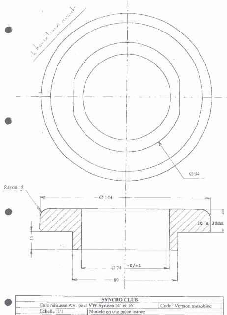
Here is drawing I found in my files for Beau, pretty close to my estimates I mentioned in comments. Thickeness can be altered to suit of course. Don’t forget the multiplier effect of shim to effective lift.
Vanagon – syncro – VW tool 3141 substitute
Posted by albell in syncro, syncro specific repairs, vanagon on July 17, 2012
As I am planning on fiddling around with my syncro’s front springs and shocks I thought I might need a tool to guide the top of the shock back into position when re-installing. Bentley calls for VW tool 3141, the best pic I could find with a quick search is this Snap-On one. I had some 1/2″ diameter aluminium rod handy, and a M10 X 1.00 tap (same thread as used in pressure sender on engine, I needed one to make my sender relocation manifold). The lathe made making the tool easy, shaft is a press fit into handle and is pretty secure, but I probably still need to blob on a bit of weld on the joint.

End of shaft.

End of old 2WD front shock – it has the same thread.

Tool screwed onto end of shock.

I hope to be able to show you how it is used when I pull the front springs from the van, but I need to borrow a spring compressor before I get going with that.
Vanagon – syncro upper control arm bushing replacement
Posted by albell in syncro, syncro specific repairs, vanagon on July 15, 2012
So on our last trip I noticed a squeaking when suspension moved, noise coming from front driver’s side. I suspected upper control arm bushing so I set about replacing them on that side. It is a pretty straight forward job, and here are a couple of diagrams illustrating where the bushings are.


I jacked up and supported driver’s side front of van and removed wheel. When I detached the upper ball joint I could move the control arm by hand, and the squeak was there. 19 mm nut on one end of camber adjusting bolt, other end is 14 mm socket. Arm off and in the workshop.

Close up of one bushing.

Other side of bushing. There is a good chance these are originals.

Here is one of the new bushings. Vaico brand, I don’t know where they fall in the quality line up, but I got them in trade for some used vanagon parts. There is a great Samba thread on UCA bushings here.

I wondered if an O-ring would help keep any grease in.

Then I tried some silicone over the O-ring, a variation of what Tencentlife did in above mentioned Samba thread. I ended up removing the silicone and adding a second O-ring.

Now getting the old bushings out. I don’t have a press so I used a bit of aluminium tubing, a biggish socket, and an old 2WD control arm bolt, and a heavy hammer to drive the bushing out.


Look at that clutter. Workshop is in a real sorry state.

Old bushing out.

Bore of UCA where bushing fits. On the syncro it is a simple press fit, no spot weld needed.

Using a vice to press new bushing in.

Part way in. Ok, you’ve noticed that I painted the UCA. A very casual crap job and wasn’t needed (original paint still good), but I had a can of orange paint and I thought it might look cool. Overnight drying time was not enough, paint still soft, came off here and there. Perhaps I should lock up the paint.

A bit of pop can in UCA to keep a large socket in place while bushing driven home.


And the other bushing pressed in.

Out at the van, rear of support where bolt goes through and eccentric washer sits.

Front of support.

Rear eccentric washer in place. It was a fiddly job offering up the UCA into correct position and not have the washers fall out.

But in it went finally. Everything re-assembled. Guess what? I still have a squeak!

Next post will deal with camber adjustment and perhaps finding the squeak.
Trip – Camper Creek watershed
Just back from a couple of days exploring the area NW of Port Renfrew. My wife and I made a trip there back in May but bad weather limited how much exploration we did. This time it looked like our summer had finally arrived so we headed out there to see what was what. Turned out the gate on Grierson main was locked so we could not make it up to the nice view point we camped at back in May, so we headed west on Camper main and found a spot just on the southern edge of Walbran Provincial Park. Yup, another campsite on a logged off area – we joked about writing a book “Slash Camping on Southern Vancouver Island”.
But the view was magnificent, looking over the logged area of Camper Creek watershed, to the south and west the virgin forest of Pacific Rim National Park (West Coast Trail), and Juan de Fuca Strait and Washington to the far south. This panorama doesn’t show the park boundaries, but just to orient you, Port Renfrew is pretty well behind that dip on the left.

I’m not going to go on and on trying to defend our habit of camping on logging spurs, we’re just different, ok?

A bit of haze was coming in over the straits as the sun set.

Next morning, thick marine cloud had arrived.


We packed up and headed down the slope and further west, exploring spurs and dead ends. All the way to the Pacific Rim National Park boundary. On the way we found another logged view point. You almost can see our first night spot back up on the ridge to the left, middle of pic, narrow vertical grey logged area.

About 950 metres further west is the National Park boundary, it is logged right up to it.

I don’t know why I take pictures of giant stumps without some object in frame to give an idea of size, but I do. This cedar stump really is bigger than you think.

Had a look at Sandstone creek.


And then back up to to the previously scouted campsite.

It really wasn’t that bad. See the cloud still on the deck in the background?


The low cloud made the sunset quite spectacular.


The cloud started to form around us after the sun went down.

And in the morning, we got the cloud full on. Damp and chilly.

On our way back home, we stopped at a spot on the Gordon River, a few km upstream of the marina.

All in all a pretty good trip. No one got hurt, no van problems, no run ins with bears (plenty of bear poop around), and plenty of food and drink. What more can you ask for?
Addendum: some more pics from trip.
We often came across signs of cedar shake block cutting, folk salvaging something from left over wood. On this trip it was all Red Cedar, on our previous trip in the area we saw Yellow Cedar shake block cutting too.


Apart from locked gates (mostly to restrict access to active logging areas – protecting machinery), many roads are “decommissioned”. Can take the form of large ditches and gravel berms across road, or taking out bridges. The latter shown in this pic, and a tree across the road to stop folk before they go over the edge.

My quick and dirty levelling ramps worked fine.

One of our two dogs looking noble. We don’t usually have any problems with them and the local wildlife but they have chased off a bear on another trip.

And here he is, dog tired.

As I mentioned before, lots of bear poop around. I think the bears are feeding on Salmon Berries.

Another shot of the marine cloud and West Coast Trail boundary. Where I took the pic the temperature was in the mid to upper 20’s C. Next day when we were in the cloud it was around 14 C. We were sympathetic for the hikers on the trail, they probably had no idea it was so nice and warm 150 metres higher.

Not the biggest slugs in the world, but pretty big.

Some of the sandstone outcrops.

Vanagon – another use for scrap aluminium
Posted by albell in syncro, vanagon, vanagon mods on June 25, 2012
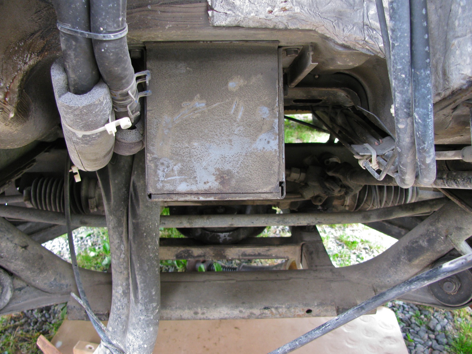
This time a bit of aluminium grating and it couldn’t have been easier to make – I cut it into two sections. Looks like it might work out in the field using rocks or wood to raise one end. BTW, my transmission bash plate seems to have generated a lot of chatter about increased transmission temps due to reduced air flow over the transmission. As with most internet chatter, no data given to support opinions but I hope to be able to do some temp measurements using IR gun (yes Simon, I’m going to ask to borrow it).


Vanagon – syncro bash plate project finished
Posted by albell in syncro, syncro specific repairs, vanagon, vanagon mods on June 24, 2012
Well the transmission protection part anyway. I decided to leave the plate mostly rectangular, but I did have to curve the front corners for no other reason than I thought it looked better. I also drilled some drain holes at the rear of the plate. Instead of using the drill press, I used the wrist buster, aka Van Dorn drill.

I made rather ugly holes with it, but I rationalized that (and other goofs) with the “it’s only a skid plate” mantra. I cut out slots for the stock skid bars and bent up the leading edges slightly. You can’t bend up that middle section too much or it will hit the nose cone of the transmission. I also gave the bottom of the plate some DA love.

I found it a real pain in the arse installing the stock skid bars by myself, but installed they were. See how exposed the transmission appears? Like having your goolies hanging out.

And same view with the plate installed.

Front view.

I think the extra width will help protect the inner cv joints and the fuel pump. Note to Simon, will also protect the speed sensor and that big electrical plug on driver’s side. But not sure about fitment around exhaust on your 2.5 Subie.


Next job will be to add some 1/4″ aluminium plate between the propshaft protection bars, and perhaps to extend that protection out sideways and attach to frame rails. That will help protect shift linkage and coolant hoses.
Damn. just occurred to me, forgot to paint the stock skid rails where I ground off the paint for welding the tabs on. I guess the project is not quite finished.
Vanagon – syncro bash plates project
Posted by albell in syncro, syncro specific repairs, vanagon, vanagon mods on June 22, 2012
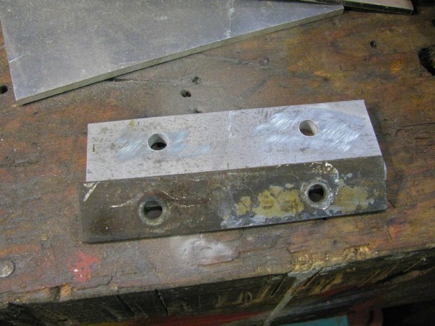
I left the entire syncro drivetrain protection bars off my van after the propshaft business with a mind to installing some bash plates. The transmission is left pretty well fully exposed in the stock set up, and today I started doing a bash plate in that region. I had some scrap yard sourced 5/16″ aluminum plate to use.
Here are the stock skid bars/rails, transmission end. See the added tabs?

I had my first go at TIG welding…I still have a long way to go.

A real welder (good friend Dave) did the stainless to plain steel weld (609 rod).


Pretty heavy gauge aluminum, but it was cheap.

I match drilled and countersunk holes in the plate to match the nuts on the rails. The tabs with nuts were not located with any special measurement in mind.


Other side view. I’ll offer the assembly up to the van and see how much of the plate I’ll cut away. Rough sketches on plate sort indicates my thinking, “wings” towards the rear to provide a little protection to the inboard cv joints.

Project finished, blog post here.
Vanagon – radiator replacement (mine)
Posted by albell in syncro, syncro specific repairs, vanagon on June 21, 2012
Not really much to add to the previous rad replacement expect that it is my van (’86 syncro) and I thought I’d make it a post just for my documentation/memory aid purposes. I suspected my rad needed replacement for no other reasons than I think it is the original rad and that I noticed the rad fan coming on more often when idling after a hwy drive. The replacement is a Behr unit, made in South Africa. The old rad still had the a/c condensor rad attached in front, probably not helping heat escapement. The new rad did feel lighter than the old one, whether this is due to deposits in old rad or construction details I can’t say. No real details to note except that it is a pretty easy job. I clamped off the coolant lines so a total coolant replacement was not done, I glued on the little rubber washers on the spikes on top and bottom of the rad (so that they didn’t fall off during installation, and I sprayed Fluid Film on exposed fasteners in the general area. After install and bleeding, I have only idled van long enough (took 20 minutes) to get first stage of fan to come on, no road test yet.


Vanagon – that transmission noise fixed?
Posted by albell in syncro, syncro specific repairs, vanagon on June 7, 2012
I’m just back from test drive after installing my re-bushed propshaft and I can report that the noise I was hearing, and that I had thought was transmission noise, has gone! I’m chuffed!
But to ward off the Evil Eye, I’ll not claim victory.

Vanagon – making new syncro propshaft internal bushings – Part 2
Posted by albell in syncro, syncro specific repairs, vanagon on June 6, 2012
I decided to make a split bushing for the internal location. I first turned down some Delrin to final inner diameter (23 mm to match the turned down yoke shaft), then mounted it on a mandrel to turn down OD to 28 mm (was OD of upper bushing and I guessed that the inner one was the same).


I kept the bushing on the mandrel and clamped it in my wee milling head. I also used a small C-clamp on the bushing to stop it from popping off during slot cutting. I used a 1/8″ end mill to cut the slot, made the slot 6.8 mm wide (chord length) which I estimated to be slightly more than needed.

Finished split bushing.

And as I tried to install it, I realized I had no way of holding it compressed to get into the narrow bore, no grip after it goes into outer bushing area. Oh, btw, this is how the bushing should appear when it is finally in place at the bottom of the housing.

I had an idea, some stainless shim stock to act like a funnel.

That worked and I was able to tap the bushing home. You can make it out, down at the bottom.

The yoke shaft would not fit in, I had to chamfer the end of the shaft a little more, and polish the end. But I finally was able to tap the shaft in and it is nice and snug. Quite snug actually, it takes about 20 Nm to rotate the yoke, but no radial movement at all. Oh and another thing, I removed that flange on the upper bushing, didn’t make any sense. I’m feeling quite chuffed in managing to get some sort of bushing replacement made. I hope they will wear well.

Vanagon – transmission noise hunt
Posted by albell in syncro, syncro specific repairs on June 1, 2012
For the last couple of months I have been noticing a slight whine/howl when driving no load/coasting, in 3rd/4th or neutral, clutch in or out. Only in a narrow speed band, 50 – 60 kph. I’ve discounted rear wheel bearings and I resolved myself to having trans. taken apart and examined. So I started the pull process, first with skid bars and propshaft. After they were out I decided to drive van and surprisingly the noise was gone. So what does this mean? Maybe front diff is making the noise or is the removal of propshaft affecting whatever is noisy in transmission?
I pulled the front diff and took the case apart, 3 sections. Front cover and rear section. Mid section has R&P and I set that up to measure lash on the R&P.
Rear section removed (note spacer not on top of VC, I took it off before pic, sorry)

Front cover removed (cover was cleaned before shot).

I clamped the input shaft so it wouldn’t move.

And then set up dial indicator on outer part of ring gear tooth.

Close up.

I wiggled ring gear back and forth and measured lash. Was in spec (0.004 – 0.010″).

And teeth looked ok. Mind you Daryl at AA Transaxle says ring teeth don’t usually show wear, its the pinion teeth that do. Hard to really see them when in case.

During removal I had to cut the vent line as I forgot to remove banjo bolt securing it to case (did same thing last time I removed diff, doh). So I made up a nipple and added a section of vinyl tubing.

So where does that leave me? Daryl is suggesting it is the pinion bearing in the transmission and I can still drive it for a while. I’m not clear on how the propshaft affects that bearing but I don’t feel quite as pressured to tear into, or have a skilled person tear into the transmission.
Addendum: Dirk over on the IG16 forum, wondered if the ring gears did actually show unusual wear. He pointed to lines parallel to the teeth. I don’t think that these marks are anything to worry about.


Simon’s hightop – installed and off on a trip
Weekend before last, the hightop was installed on Simon’s ’91 syncro westy. Late night and quickly thrown together video of install.
And then this last weekend he took it on a trip.


Inside is insulated and carpeted, but side cupboards and little details still need to be installed.


Big difference from the start.
Overnighter NW of Port Renfrew
We grabbed the chance to do a little exploring on the south end of the island (Vancouver Island), specifically just northwest of Port Renfrew. The area you get to if you hang a left instead of a right after the high bridge over the Gordon River.
Typical, secondary and not heavily used logging road.


Further on, around 680 meters elevation, some old growth but mostly second growth (guessing old growth cut in the 60’s-70’s, perhaps later). Lots of Yellow Cedar, one down across road but a section at end cut and easily moved to get past (yes, patch of snow there).


And found a nice viewpoint to camp.

Olympic Peninsula (USA) in the distance, Cape Flattery on extreme right.

Like a bad haircut, or having a hightop on the van, the campsite was fine looking out, not so bucolic looking in. Still, no one around and plenty of firewood (felt like a millionaire burning Yellow Cedar, the scent is divine).


Tired dogs.


A couple of little lakes close by, here is a glimpse of one.

The clouds and rain moved in next day.

The “Excelsior” proved its worth at breakfast time.

Typical view when rain comes, looking north east.

We spent the wet day exploring the roads a little, but the low cloud made it a silly exercise. couldn’t see much. Headed back home via long loop up via Gordon River watershed and Cowichan valley (some pics of Gordon River area in this post). All in all a great little trip.
Oh, forgot to include one of those “same place, different time” shots. Side road on Gordon Main (TR4 I think), again on slash, where my son and I camped overnight while exploring region last year.
Then:

And now:

Addendum: I was asked about pressure cooker beside “The Excelsior”. It is my EKCO model I use winter camping and in the van, had it for 30+ years. I bought it second hand and it seems the model at least, dates from the ’40’s. Found an ad at this site.

Vanagon – eccentric stub axle?
Posted by albell in syncro, syncro specific repairs, vanagon on April 22, 2012
(note: holding stub axle by the splines was an error duly pointed out by David in the comments. Axle re-measured and post updated.)
I was complaining to Phil Z. about my wheel bearing failure and he suggested I have a look at the stub axle. So I chucked it up on the lathe, holding it by the splined outboard end (was careful to have the chuck jaws positioned correctly on the splines) and then I measured a couple of things.
Where the outboard bearing seats had 0.009″ runout.

At the inboard bearing seat I measured 0.015″ runout (sorry, fuzzy pic slipped past me).

Where the seal rides, 0.020″.

The face where the CV joint mates had 0.010″ runout.

I did not measure that outer edge of the CV mounting flange as I thought eccentricity there was not important as the cv is aligned by the bolts.
And here is a quick vid of the assembly spinning.
What does all this mean? How does a new stub axle measure up? Was this runout the cause of my bearing failure?
Addendum: Crow eating time. David’s points about where I was grabbing the axle (splines) was correct. I re-measured runout with axle held by outer bearing seat.
Runout at inner bearing about 0.005″.

At seal, 0.007″.

Flange face, 0.002″.

Looks a lot better in motion.
So there, no smoking gun after all.
Vanagon – cooling system leak
Posted by albell in syncro, syncro specific repairs, vanagon on April 20, 2012
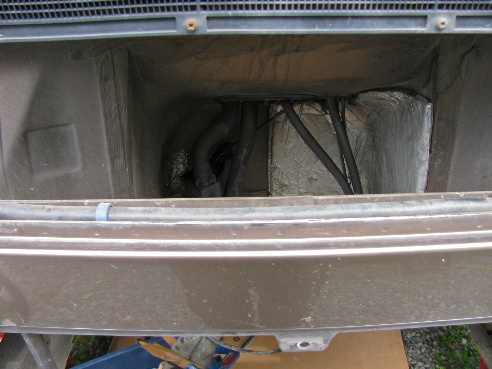
Bloody vans eh? No sooner than I fixed that wheel bearing than another problem bites me. Last couple of days I had been noticing a slight whiff of coolant when I got out of the van. I couldn’t see any leaks, inside or out. Then yesterday I noticed that my coolant overflow tank was empty and even I could not ignore the fact that I had a real live leak somewhere. I topped up the tank and fretted about expensive repairs. Today after a short drive, the smell was much more pronounced and I did find the leak. Thank the Vanagon gods that it was a hose leak, short section that runs from the thermostat to the lower of the two crossover pipes at the front end of the engine.
This pic from above does not show any wetness (the bad hose is the lower, thick one). Update: I think it is this hose featured at Van Cafe.

But from below, you can see the marks of a leak.


I had to remove a bracket that holds the remnants of the Webasto coolant heater system to get at the short hose, and remove the bell housing vent to get it out of harm’s way (syncro bell housings are sealed to the motor and a vent is provided that leads up somewhere above the gas tank). No surprise I suppose when I broke the plastic elbow when removing the bracket, so it goes.

With the bracket out of the way, I could get at the hose. Off it came and time to look at it closely.

Just a pinhole really, but big enough to piss away 1 litre of coolant in about 30 minutes of driving. I had some used hose that I took the chance with, and I got it back in place. I had a closer look at the broken vent elbow, it was plugged solid with some sort of crap.


Then I made a jury rigged repair to the vent elbow using some silicone tubing, stainless tubing, and a bit of stainless wire wrap.

Yeah, I know, this hose leak is a not so gentle reminder that all of the cooling hoses on the van are old and tired. The thing is, I have it in mind to swap in a different motor so I’m being a bit cavalier with this old wasserboxer.
Vanagon – getting that 46 mm wheel nut off
It occurred to me that I should have mentioned how I removed the 46 mm castellated wheel nut off the rear wheel in the last post about the bearing failure. The nut is on there good and tight, Bentley says to torque it up to 360 ft lbs (for the 10 slot castellated nut, the older 6 slot nut was torqued to a lesser value, something like 285 ft lbs). I don’t have the heavy duty air tools that would handle this but I do have a 3/4″ drive, imperial socket that fits (1 13/16″ – handy metric to fractional imperial chart here), corresponding tommy bar, and a 3 ft section of thick walled steel pipe. You can apply a lot of twist with this set up and can even get a fairly good idea of torque applied if you know your weight and where about on the pipe you are applying it. You know the drill, 100 lbs of weight one foot from the axis of rotation is 100 ft lbs, same weight two feet out is 200 ft lbs. You loosen the nut before you jack up the van, and have the handbrake on. But the other day when I was doing the bearing job I had a dickens of a time getting the nut off without the wheel turning and the van moving, and it was impossible to loosen the nut on my parts van as the transmission is out and the free end of the axle was just hanging in space. I did try the slug wrench mentioned in my original post on wheel bearing replacement, but it did not budge the nut.
So how do you stop the wheel from turning when you are grunting down on the end of the 3 ft extension? Well, you have to jack van up and support it securely on good jackstands. Remove the wheel, and use the lug nuts to secure some sort of metal bar to the brake drum. I have lots of scrap bits of aluminium around, so I used some 1/8″ 3/16″ thick angle. The angle bears on the ground stopping the hub from turning. Here is a snap taken today when I pulled the drum and hub off the other rear wheel to have a look at the brakes. Not very clear in the pic, but there are 2 lug nuts holding the angle to the drum. Note also the old house jack supporting the socket extension.

This really worked, no drama, no movement of the van. Used the same technique when tightening the nut.
Oh and here is what I wanted to look at. With the hub out of the way I could see the gubbins clearly and I wanted to be sure all the brake springs were installed correctly (I *think* they are). Plus I wanted to pull off the threaded adjustment bar and clean it up so that it would actually adjust (I hate the Vanagon rear brakes).

