Vanagon – heater control light, LED hack
Posted by albell in vanagon, vanagon mods on November 25, 2011
Years ago I made some LED lights for the instrument clusters before they were commercially available. They didn’t look pretty, but they worked. On my old neglected website I have some pics and text.
I still have those early models.

If you want to see how to make a much neater version, check out this German site. Don’t miss his clock lighting fix either.
I also hacked up a heater control bulb/socket to take an LED. I am embarrassed to show this effort, but as ugly as it is, it does work.

So embarrassing that I had to have a go at it again. Here is a burned out stock bulb/holder.

If you look closely at the slot in the plastic you can see a thin copper wire attached to the silver spade connection. Right adjacent to the “step” in the plastic the spade has a bent inward tab that secures the bulb and the spade in the holder. Bend up that tab (one on each side of the holder) and the bulb and spade will pull out.

I clipped off the bulb and then soldered on a resistor. Btw, you can decode that resistor value yourself 🙂 and there are online calculators to determine what resistor to use using led voltage rating and supplied voltage.

Then the spades were soldered on.

And the whole shebang pushed back into the holder. The resistor prevents the led from being inserted fully, but it is pretty secure as is.

Not perfect, but a whole lot better than that early mess. I’ll take some pics at night to compare with the stock incandescent.
Update Nov 28 2011 – being absent minded, I installed the led modified lights in the heater controls and the rear heater fan switch without taking pics of before swap. To be honest, it is a bit of a “meh”. It does match the rest of the dash now, but I can’t help but wanting something better, brighter. It was a 10,000 mcd LED in the heater control light, pretty bright I thought, but not as bright as I want.
ATA – scrapyard finds
Posted by albell in aircraft, around the airport on November 25, 2011
Local metal recyclers must have a contract with one of the aviation companies around here for I’ve been seeing more aircraft parts in the yard. Wing sections, helicopter sections, and recently – these motors.
Update: the engines are from the BC aviation museum. Sometimes hard to understand why museums chuck stuff out, but there are space and money constraints I guess.


Vanagon – heater control lights
This post was prompted by some Vanagon mailing list members being unaware that the heater controls are supposed to be illuminated, and the light can be dimmed by the dash light dimmer control.
Some warnings about taking off the heater control faceplate. The faceplate plugs into the dash via 2 posts on the back of the plate that fit into holes in the dash. One is located at the lower left of the plate, the other the upper right, but not at the corner, about 1.5″ to the left. A small pry bar or an old table knife can be used to gently pry the plate off. Be gentle, just as with practically all of the plastic in these old vans, the posts can be brittle. When the face plate is off, lightly coat the posts with grease to make later removal easier. The heater control knobs also can be stuck on tight. Try not to pull on the rubber knob at the end of the lever, and try pushing the lever in a little before pulling out. Again, a bit of grease will help in the re-install and removal when you go at them some other time.
So here are the controls illuminated.

Now to take the face plate off. First pull off the fan switch knob. Next carefully pull off the heater control levers (note their orientation first). Be careful, try and control the tugging so that when the lever moves it does not catch on the plate and break it. Squint in the slots and you can see how the levers can catch on the edges of the slots. The old table knife comes in handy again, pry down the lever to guide it out of the slot as you tug. Then pry off the plate. A word on putting those levers back on – use the table knife (again!) to pry down the metal arms in there, as you push the lever on.


The grey/blue wire is power from the light dimmer rheostat, the brown wire is ground. The bulb is integral to the black bulb housing so it has to be replaced as a unit. Here is a white bodied one from Van Cafe. It is the same bulb that is used in the rear heater fan switch.
Update: Dave M. wrote: “I was recently (in the last 3 months) able to go to my local VW dealer and obtain replacement bulb sockets with replaceable bulbs. You tell them apart as the ones you can replace just the bulbs in are white sockets instead of black. The sockets themselves have the same type wiring connection, so it is simply plug and play.” I wonder if this is the same as the white bodied one from Van Cafe?
Now that rear heater fan switch. Remove the knob and carefully pry the face plate out. Its should pop out, but to be honest you will reduce the chance of breaking one of the little plastic tabs if you reach in through the heater controls hole and prise the tabs from behind.

And here is that same bulb and bulb holder, popped out of the switch plate for this shot.

I have hacked into one of those bulb holders and wired in a white LED and resistor. I’ll go into that in another post. Hope this helps a bit Annie 🙂
Vanagon – changing the colour of cool white LEDs
Posted by albell in vanagon, vanagon mods on November 23, 2011
Last year I bought a set of LED festoon lights to replace the interior lights in the van and one for the glove compartment/map reading light. For some reason I bought cool whites for the interior lights and a warm white for the map light. I tried to convince myself that the cool white gave a clean and modern feel (ha!), but no, as friend Simon puts it “it’s like a morgue”. I have 4 door activated interior lights; driver’s door, passenger door, and one on each side at the back seat area. So the morgue effect is throughout the van. In contrast, the map light does give an acceptably warmish cast.
I suppose I could buy new LEDs, warm white, but no, I have to try another route. I was talking to the lighting guy at a local theatre and we got onto the subject of lighting gels. I explained the morgue situation and he gave me an old Lee 204 gel. The specs for this filter can be found here.
Here is the filter:

I cut a little strip and wrapped it around the festoon LED and secured it with O-rings. I thought that just putting a rectangular bit of filter in the light housing would allow some cold white to “leak” out of the ends.

Back into the light housing.

And the result? Well it is different, warmer. Will have to wait until dark to really be sure it works, but the comparison pics are promising.
Unfiltered:

Filtered:

Update: After dark test – still not as cozy as incandescent lights but much better than before.
ATA – float plane tugs
Posted by albell in aircraft, around the airport on November 22, 2011
Wet and stormy here and I can’t be arsed to photograph the viscous coupling plate pairs and comment on the wear patterns and present the theories of plate shape and hump condition. So instead, here are three pictures of float plane tugs taken today.


Vanagon – syncro viscous coupling anatomy – part 1
Posted by albell in syncro, syncro specific repairs, vanagon on November 21, 2011
This post is just to clarify, a little, how the plates inside a viscous coupling (VC) are arranged. My post on replacing a VC shows more pictures of the assembly and the seals.
Maybe a couple of pics of the VC (end plate removed) to set the scene. Note the end shims, and the absence of the circlip (groove for it in shaft is visible) that keeps the plates all together.

Another angle, end shims removed.

There are 24 pairs of plates in the VC. One set are keyed to drive (or be driven by, semantics) the VC housing itself. So these plates have notches around the edge that fit in internal splines on the VC housing. They also are the plates with the circular holes in them. The other set of plates, slightly smaller in diameter, are keyed to drive the central splined shaft. They have slots in them. The propshaft from the transmission is connected to the housing, the pinion of the front differential is connected to the central shaft of the VC. The silicone fluid filling the VC is what mediates the power transfer between the plates. I won’t be going into the silicone fluid in this post.
There are spacers between pairs of plates, and these spacers fit into the hole in the middle of the plate that is keyed to the housing. The spacer is (all measurements are approximate) 0.065″ thick. The plates themselves are 0.040″ thick. So with the spacer partially lying in the hole of one plate, it only projects about 0.025″. That means the plate pairs are separated from each other by 0.025″. I think it is time for a simple diagram.

Does that diagram make sense to you? You can make out the spaces between the plate pairs in this picture of the entire stack o’ plates out of the housing but still on the shaft.

Oops, looks like I left the last plate in the housing. Also the aluminium ring I am using to support the plates is causing the plates at the end to be pushed upwards. Of course when in the housing they are all aligned. Here is a closer view, no mistaking the pairing of the plates.

And here is a stack of 2 pairs, plus one shaft keyed plate on top.

I think I have established that the plates are in pairs 🙂
I’ll post pictures of the wear patterns on the plates and try and relate that to the pairing of the plates in the next part. All comments and corrections welcome.
Vanagon – radiator replacement
Last week I swapped new radiator into my friend Simon’s 91 syncro westy. What forced this swap was the failure of the threaded insert where the fan thermoswitch goes. We were trying to install a new switch (old switch was not working properly) and the insert just gave up the ghost.

So Simon left the van at my house and came back a few days later with a new rad and I had the pleasure of doing the install. A bit of background on this van’s radiator, about a year and a half ago we did the thermoswitch replacement, the story is told here. I think I should have nagged Simon a bit more to get a new rad back then, that eroded switch could not have been a good sign.
Removing the rad is a pretty straightforward, if messy, job.
– drop spare and remove clamshell
– clamp off coolant lines
– disconnect wires to rad fan
– remove upper and lower grills
– disconnect thermoswitch (obviously I did not need to do that!)
– remove the (probably rotten) cardboard wind deflectors from around the rad
– I found that removing the passenger side “L” bracket ( 2 X 13mm bolts) first allows you to get access to the spring clamps on the coolant lines, leave the driver’s side bracket untouched for time being to hold the rad in place. Passenger side bracket removed:

Note: see the rubber washer on the plastic”tit” between the coolant hoses? There is a tit on each corner of the rad, the upper ones fit into holes in the van body, the lower ones into holes in the “L” brackets. Don’t lose the rubber washers. Well, go ahead, lose them. Garden hose washers would probably make an ok substitute.
Driver’s side bracket still in place (pic taken before I removed the lower cardboard wind deflector):

– cut or undo any cable ties holding up the coolant hoses or the fan wiring so that the radiator will not hang up when it comes down.
– remove the driver’s side “L” bracket. Careful, the rad will drop down.
– drag the bugger out from under the van and swap the fan and shroud ( 10 mm self tapping screws) over to the new radiator.
Installation is harder than removal as you have to fight gravity and get those upper tits into the holes while lying on your back below the van. A helper at this point would be, well, helpful. Don’t forget that the driver’s side “L” bracket interferes with the spring clamps on the coolant hoses, and don’t forget to push up on the “L” brackets as you tighten the bolts to make sure the rad is seated tightly.
Now the fun part, Sawz-All plus Simon meets the old rad. He cut it in half then cut the plastic end caps off. We found the remains of the threaded insert and a whole lot of gunk at the bottom of the rad. Remember it is a 2-pass rad, hot comes in and directed by end cap up to upper half of rad, then it goes across from passenger to driver’s side and down the other end cap, then back across lower half. The junk was found in the lower, passenger side, ie just before the exit and just below where the thermoswitch (rad fan) is installed.


Note: I drained all the coolant and flushed the system on this van, then recharged with fresh coolant. I found bleeding the Vanagon and Subie EJ25 combo to be much more of a chore than stock or my old inline four in my ’82 westy.
Vanagon – local meet November 2011
A hardy few met at Beaver lake today. All Westies (if I can include my conversion), three syncros and two 2wd. One Tdi, one Bostig, one 2.5 Subie, and two stock wasserboxers. Was fun to kibitz and see each other’s vans.
Vanagon – sliding window rain screen – improved
Posted by albell in vanagon, vanagon mods on November 17, 2011
My friend Stephen improved my sliding window rain screen by making larger cutouts at all four corners. I think this will keep out the rain better.
Update Feb 4 2020.
Here is a very quick and dirty pdf drawing of the screen. My old draughting teacher would be appalled. The width of the screen could be adjusted to suit, my first version was narrower.
window-screen-drawing-v1-1.pdf


Nostalgic
Except my old Beetle was pale blue and the rack was on the rear, but the skis were wooden.
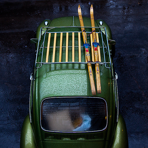
Here it is, Pine Pass in Northern BC, December 1978.

And my travelling companion, same place.

Vanagon – sliding window rain screen
Posted by albell in vanagon, vanagon mods on November 15, 2011
Simon’s van is modelling a quick project made with a bit of scrap 1/8″ Lexan. The dimensions are 7.5″ X 17.5″, and the corners on one side cut out (about a 1″ radius). The idea is that the screen stops the rain from coming in the sliding window when it is opened for ventilation. To be field tested, I don’t know if I made it too long, it bulges out a fair bit.
Update: see here for improvement.


Vanagon – Westy kitchen panel graphic
Posted by albell in vanagon, vanagon mods on November 11, 2011
Jim Felder made this up, kudos to him. He writes:
“Today I got ambitious on a project I have been wanting to do for a long
time. It’s a replacement overlay for flaking, peeling and rusting front
panels for 83-up vanagons. It’s in brown, of course, because that’s what I
have. If someone will scan a grey one, I will make that version available
(I need to get the color right… if someone just wants to scan and sample
the CMYK mix in photoshop, that will work too).
You should be able to have this printed out on a variety of substrates,
depending on the capabilities of your local sign shop. Cut out the holes
for the LEDs (white circles, you may even be able to get this printing on
the backside of lexan with clear windows for the LEDS instead of punching
them out). Remove your old metal panel and sand and respray it. Cut the
printed file out at the outline, it should fit exactly within the debossed
inset of your panel.”
pdf file here:
Here is a jpeg version:

Vanagon – found object
I found this back in ’93 when cleaning out an ’82 diesel westy that I was re-selling. Also found a South Pacific missile base souvenir lighter, but I can’t lay my hands on that right now.

ATA – fly past on November 11
Posted by albell in aircraft, around the airport on November 11, 2011
Heard the drone of multiple piston engines around 1015 this morning, caught them on their second pass. Nanching CJ-6.


ATA – Vickers Viscount at BC aviation museum almost finished
Posted by albell in aircraft, around the airport on November 10, 2011
The museum is only a 5 min drive from my house, and dropped by this afternoon to get my fix. The restoration of the Vickers Viscount is almost complete, the interior looks great. Other pictures of the Viscount can be found here and there on this blog, more pictures and the history of this particular plane is found here. The Harvard in the workshop just got a fresh coat of yellow paint.
Viscount cabin looking aft.

Ditto, looking forward.

Harvard.


Can’t get enough of the Douglas A-26 Invader.

The light was all wrong to get a shot of the cockpit. One day I have to ask to sit in the left hand seat.

Viscount and Invader.


Beautiful.

Vanagon – D15 connector issue
Posted by albell in syncro, vanagon, vanagon mods on November 2, 2011
Yesterday, driving the ’86 syncro, going down a long hill and the van died (noticed when throttle re-applied). Pulled over and it started back up after a couple of tries, funny I thought. Got to my destination and parked for a few hours. Then I tried to start the van and it turns over and catches for a second then dies. Try again, same, then subsequent tries has it turn over but no start. Noticed no fuel pump noise with ign on (and my van does cycle fuel pump with ign on.)
Looked in the engine compartment with ign on. No hum from idle valve. Pulled the fuel pump and ecu relays and replaced with new (during which I jumped contacts and did get fuel pump to run). No change, no idle valve hum and no fuel pump, and no start.
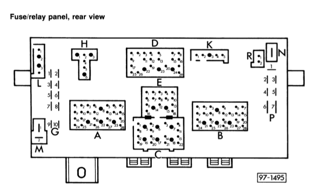
Then I pulled cover from fuse panel and pushed on fuses and generally jiggled panel. Fuel pump cycled on, and I could start the van. Drove home with no problems. I suspected the known problem of the D15 connection on the back of the fuse panel. This connector supplies power from ign switch back to engine compartment and can power (depending on van year and VIN) the fuel pump relay, the idle control unit, coil, and the crankcase breather heater. Gets a little muddled in that the crankcase heater was retrofitted to early ’86 vans (and that seems to be the situation in my case). The wiring diagram shown below is specific to my van.

No matter what version you have, the D15 connector is oveloaded. Note in the diagram there is another connector in the “D” plug that is on same current path as D15. This unused connector, D23, is a bigger Molex than D15. Today I pulled the fuse panel down and removed the “D” plug. D15 looks like it has overheated.

I couldn’t find a spare larger Molex connector to make the switch over to D23, but I did put a new connector on the black wire to D15 and spliced in a pigtail so that when I get the right connector I can plug in to D23 (see the unused larger hole at the bottom?).
Update: I did finally find a large female, molex type, connector for that pigtail, and it is installed into D23.
I can’t say for sure that this connection was responsible for my no start problem yesterday, seems likely though.
Addendum: dug up the Samba thread on this subject, worthwhile reading.
Trip – curtailed short trip in Sooke
I thought I could make a circle route coming back on the north shore of the Diversion and Bear reservoirs, but active logging and an unexpected gate foiled me. Ran out of daylight and camped in slash. Next day was raining and I had brought the wrong fishing rod so I had no real excuse for not coming home.
Still had skinny summer road tires on (Agilis 81). They look like train wheels.
Vanagon – syncro viscous coupling replacement
Posted by albell in syncro, syncro specific repairs on October 23, 2011
I pulled the front diff. on the syncro today to replace the old failed (weak) viscous coupling (vc) with a good used one. Dropping the diff. is in the Bentley manual so I won’t describe that part except to say that it takes a bit of wiggling to get it out. I used a motorcycle lift as a transmission jack. Once out I set it on a container to drain.

See the dark dirt on the input end? Looks like the oil seal there is leaking, need to attend to that. Once most of the oil drained out I humped it onto the bench, just to look at it.

See the speedo drive sticking out? Then it’s on to the floor and off with the 13mm bolts holding the skinny end on.

Some tapping with soft faced hammer to break the seal and it comes apart.

Yup, that’s the vc sitting there, with a spacer on top.

The vc just lifts right off, exposing the speedo drive gear on the pinion shaft.

Closer view of speedo gear.

With the case separated I drained the remaining oil, applied some sealant to the mating surfaces, put the new vc on the pinion (and didn’t forget the spacer) and the skinny part of the case re-installed and torqued down. All well and good, refill with oil in the morning. Now the interesting bit. I had to take the end plate off the old vc, I was dying to see the inside first hand. The big C-clip came out easily.

That end plate should then pull out, but it wouldn’t come. I thought maybe if I drained the vc and also run an awl around the edge of the plate to remove gunk it might help matters. The silicone flowed out, not as viscous as I have seen in those German videos showing refills, and looking like it might have some gear oil in it. BTW, didn’t smell bad.

Got the end plate off.

Removed the C-clip on the shaft (barely visible in above pic) and pulled the first two plates out to look at the adjacent surfaces. Need any more evidence that the plates do come in contact during hump? Upper plate in pic has been flipped over.

Close ups.


Accepted wisdom is that a weak vc is due to the silicone fluid leaking out. One could expect an O-ring to fail with time, but what I found was something else. I had a look at the X-ring that seals around the central shaft (there are two, one on each end, the one shown is in the end plate). It appears that the X-ring is twisted in the groove, look.

Out it comes, yes, it is twisted.

Another view (damned cat hairs, get everywhere).

This surely must have happened at the factory, a lip of the X-ring getting caught on the shaft during assembly. Tsk, tsk, Steyr-Puch.
Addendum: I’m assuming the vc had leaked some fluid, but even with that folded X-ring I have no proof. The “dirty” fluid from the vc could be gear oil contaminated or it could be metal particles from the plates. Perhaps I can use a magnet to determine?
Foals and chicks
We have a few hens who have escaped their confines and have been hatching chicks here and there. This is the last brood, October 9. Plus a couple of pics of foals and mare.
Vanagon – nice find at the wreckers
Posted by albell in vanagon, vanagon mods on October 18, 2011
No heating element for the seat, but the switch and the relay/controller (and wiring). I understand the 2 seat switch will fit in same hole in the steering column upper cover, but of course will need an additional relay/controller.

Vanagon – A viscous coupling
Posted by albell in syncro, syncro specific repairs on October 12, 2011
Thanks to good friend Simon, I have, in my hot little hands, a used viscous coupling. It might be on its way out, getting aggressive after a long hot drive, but it will be great for me this winter.
Here is a view of the front, the front differential end.

A couple of things to note:
-the punch mark up there on the rim between the circlip ends. It aligns with the casting ridge between that screw port and the rim.
– the paint on the screw ports and on the circlip ends.
Closer shot of the punch mark on the rim

The punch marks and the paint on the circlip must have something to do with registration on end cap for balancing. I doubt they were there to help rebuilders, but rather I am guessing the unit was balanced before filling (there are spot welded balancing tabs on the side of the body) and the marks are there to be sure it went back together balanced.
Here is the other end, the one closest to the propshaft.

Coming soon, the install, and perhaps (if I can get my act together) some sort of bench test of the VC.

Vanagon – power mirror repair
Posted by albell in vanagon, vanagon mods on October 5, 2011
I have manual mirrors on the syncro and they are less than satisfactory. They are small, don’t stay adjusted very well (I have gone through all the tricks to keep them adjusted), and they frost up in winter. Now I finally have collected enough used parts to get 2 power mirrors installed, as yet not powered, and not without having to bugger around to make them work.
I have one white one, complete but the heating element connection broke, and one black one which also had the same broken connection plus a broken stem. I’ll deal with the black one first. By the way, the mirror had been “repaired” by its previous owner using duct tape and lots of shoe-goo. What a pillock.
Here is a shot of the socket showing the broken stub.

And here is the part that was broken off.

The bracket that receives this stud looks like this.

The stud passes through that bracket and is held in place with a nut and spring arrangement. The lumpy end of the bracket fits into corresponding divots in the socket on the mirror arm, you can see them in the first picture. Here is the spring and nut on the broken stud. The white thing is a plastic washer, but it was cracked and not reused.

A new stud had to be made and affixed to the mirror. I had an idea and, not surprisingly, I discovered that someone else had the same idea before. SpitsnRovers posted his fix on the samba. As an aside, his website has some pretty useful Vanagon info on it. It is just a matter of tapping for a new stud to be screwed in. The stud has a 13 mm X 1.5 thread so if I had a bolt with that thread and the corresponding tap, I would be in business. But I didn’t so I wasn’t. I did have some 1/2″ NC bolts and the right tap, why not use that instead?

I used the die to make the threaded portion of the bolt a bit longer. The bolt was chucked up in the lathe and drilled out (passage for the electrical wires). Oh I am so clever eh? Well, no. I drilled the hole a tad to large.

Found another bolt and drilled the right sized hole. Shown below is the drilled and cut bolt, a 1/2″ Nyloc nut, the stock nut, the broken plastic washer, and the spring. I feel like I am becoming even more pedantic.

I then enlarged the hole in the socket and tapped some threads. Not much meat there though.

I cut the drilled out bolt to the right length, actually a little longer than the broken stud, and threaded it in with some locktite and set it aside overnight. To be honest, I had my doubts whether the stud will hold, there are so few threads engaged. Righty-oh, next day I put it back together. I used a 1/2″ Nylok nut instead of the stock slotted nut, but here it is assembled onto the bracket with plain nut (that broken plastic washer was discarded later).

It withstood cranking down on the nut, the threaded stud did not pull out. I set that aside and had a look at the mirror glass itself. The glass is glued onto a molded plastic backing, with a metal heating element sandwiched between. There are two tabs bent up from that metal that connect to the 12V power supply wires. Here is an intact tab.

One of those tabs was broken (same thing with the other mirror). I tired to solder on a new tab, but no luck, the solder would not flow onto the metal. Time for the cheesy fix, I could lift the plastic backing up from the metal enough to slip the bare end of a wire in. It helps of you heat the plastic with a hot air gun. The wire was trapped and it made electrical contact. I tested it by popping the mirror into the freezer for a while then connected a 12V source to the tabs and watched the fog disappear from the glass. To make the cheesy fix even more obvious, I dolloped a bit of silicone onto the area. This picture is of the repainted white mirror (Krylon Fusion satin black) and you can see the same repair on the back of the mirror.

I routed all the wires (mirror motor and heat) and put the darn thing together. I’ll post more about the wiring when I get around to connecting the electrics to the van, I’m happy right now to have the bigger mirrors. The repainted white mirror was put together, minus that broken white washer.

Not quite the right sized screwdriver, but close, and German. So you know it has to be complaining about my lack of mechanical skill.

And a final shot.

A word about the electrics. The heating element supply is connected to the rear window defogger circuit, so it gets power when that is switched on. That will be a simple connection. The adjuster motor (and its little magnetic clutches) is wired to a control switch mounted on the driver’s side door. I have to find a switch. I believe some mid ’90’s cabriolets share the same switch? I’ll document that sooner than later, I’m keen to see the mirrors move and de-mist.
Vanagon – looking at pop top truss head bolt alternatives
Posted by albell in vanagon mods on September 23, 2011
I hate the truss head bolts used on the Vanagon pop top. They are hard to unscrew and they rust. Some vendors sell stainless steel versions (it is a M6 x 1.0, 20mm long). Phil Z. used oval head stainless machine screws stainless cup washers (he filled the back side of the cup washer with thickened epoxy), and they looked pretty good. But I wanted try something else, something with a big head and that looked good, I only had 50% success. I made a cup washer of sorts from 1/4″ aluminium and used a M6 machine screw and I think it looks a bit odd.

I had another go, this time with the bolts that fix the pop top assist struts to the fibreglass. A bit better looking or maybe not.
 On the other hand, they don’t look *that* bad, and certainly better than what was there before. Who am I kidding? The last one looks like crap. Here is another attempt.

ATA – Scorpion Too helicopter
Posted by albell in aircraft, around the airport on September 23, 2011
It was temporarily moved out of its hanger at the BC Aviation Museum, and was tucked under the wing of the Douglas A26 Invader. Wikipedia entry on this aircraft here.


Vanagon – steering arm boot and radius arm sleeve
Posted by albell in syncro, syncro specific repairs, vanagon on September 19, 2011
It all started so easily, replacing a torn steering arm boot (same boot in all Vanagons).

I figured if I removed the ball joint end of the arm from the steering knuckle I could pull the boot off over it and and not change the arm adjustment (toe in). Out to the ball joint at that end, castellated nut with cotter pin.


I pulled the cotter pin and unscrewed the nut, then screwed the nut back on backwards to protect the threaded end, gave the steering knuckle around the ball joint a couple of good raps with a heavy hammer, then rapped upwards on the nut and the joint popped free. Nice when it happens so easily.

The boot was held on by 2 metal clamps (Oetker?) and I snipped the crimped part with some wire cutters and then pulled the boot out towards the ball joint.


That rubber doughnut on the arm locates the outboard end of the boot. The new (well, used one I had in my parts bin) went over the ball joint and up to the rack. Oh, I did put a bit of grease on the exposed ball joint on the inboard end of the steering rack. I used cable ties to secure the boot the the rack and the rubber doughnut.

Now the interesting part, while under the van I decided to have a look at that side’s radius arm rubber bushing and inner sleeve. These parts do wear out, and the sleeve rusts. I undid the drop link from the sway bar to the radius arm, the 19 mm nut at the out board end of the radius arm (inner bolt not touched, to keep the castor unaffected), and the 3 X 19mm bolts that holds the radius arm to the steering knuckle. As suspected, the sleeve was badly rusted and the bushings shot. The subframe hole also was rusty, but still sound underneath. Pretty well the same set up in 2wd Vanagons, its just that the syncro has that front subframe. Neil has a great write up on fixing his damaged radius rod mount on a 2wd Vanagon.


So I have to get new bushings, but right now I decided to make a new sleeve. The dimensions of the sleeve (found on this Samba thread) are: 56 mm long, 25 mm OD, 19mm ID. I did not have any pipe that was close to those dimensions but I had some stainless steel shafting from the scrap yard. It’s not the most efficient way of making a sleeve I admit.

etc…

I could have made a few pot scrubbers with the swarf. The finished sleeve beside the rusty one (btw, the stock sleeve looks like welded tube, and only rusty on the outside).

I slathered everything with a homemade Waxoyl concoction and put it all back together. I’ll order some new bushings.
ATA – the grass is brown
Posted by albell in aircraft, around the airport on September 16, 2011
A wet and cool spring and most of the summer but in August and now through September, the sun has been shining and not much rain has fallen. This will change soon of course, the clouds are presaging the rain to come.
Edit: Angus tell me that “the closest one in that shot is a Gulfstream G150, until recently, known as an Astra. Behind it, a Lear 45”.

Vanagon – cleaning the Shadyboy awning
Posted by albell in vanagon, vanagon mods on September 16, 2011
After about 5 years of use my Shadyboy awning was looking a bit dirty. I contacted Wolfgang at Shadyboy and he confirmed that the material can be cleaned with soap and water. Here are some pics I took, padding the post a bit, but maybe someone would be interested in how the awning looks non-deployed.

Some of the dirt must come from keeping the guy line stakes in here.

Unrolled, you can see it is a bit manky.

There are silicone plugs at each end of the grooved aluminium extrusion that the inboard seam awing slides into. The seam has a flexible rod sewn into the hem. The plugs can be pried out with a flat bladed screwdriver, just need to do one end.


With the plug removed, the hem slides right out. Notice the gap between the aluminium block with the hole drilled in it and the case? Seemed like the case might have been bent away from the block, I used a little C-clamp to draw the case back closer to the block.

I hand washed the awning using warm water and a very little bit of laundry detergent. I rinsed it well, and I noticed the water beads up and slides off the material just like it used to. Then the material was fed back into the groove and the silicone plug installed. Before and after shots.


Vanagon – headlight relay upgrade
Posted by albell in vanagon, vanagon mods on September 15, 2011
Some sort of planetary alignment must be happening, I’ve been talking to a few Vanagon owners about headlight relays, so I thought I’d post a couple of diagrams. Adding headlight relays to the van is a good idea, it redirects headlight power current away from the hi/low beam selector switch and the headlight switch. By passing the switches helps to maintain a good voltage to the lights and most likely prolongs the life of the switches. Also, if upgrading the lights to higher wattage bulbs, then relays are a definite requirement.
First off, here is a diagram I made years ago when I did the mod to my ’82 westy. For some reason I think the diagram has an error in it, can anyone see it? Seems silly to post a schematic that I am not 100% sure of, but on the other hand if one was to study it to find the error one would come away with a better understanding of the headlight circuit 🙂 Oh, one more thing, if I was to do this over, I’d run separate fused power for each relay.
Note: Mark Drillock pointed out that: “For the early diagram there are a couple things I would change. The red wires to the headlight switch and hi/lo switch are both labeled as coming from fuse S9. This is not really true and misleads people into thinking those 2 wires are fuse protected. They merely connect to the back of the fuse holder on the end that the fuse itself gets power from sharing that power source. The fuse does nothing for those red wires.”
He also notes: “Also your added note in the later diagram about the red wire to term 30 of the hi/lo switch applies as well to the earlier wiring.”
Thanks for the clarifications Mark, I’ll look for the original source file of this diagram and change it.

Edit: well I couldn’t find the original file so I dashed off a new version, quick and dirty.

And now on to the post ’85 Vanagon wiring. A couple of notes first. The power source for the relays can be the “P” terminals on the left side of the fuse panel if looking from the front, or the right side of the panel if looking from the rear, ha!
Or you can run new wires directly from the battery. Whatever source you decide to use, you HAVE TO install inline fuses close the power tap. The relays themselves can be clipped onto the top of the fuse panel if you have a couple of those relay bases that fit. This diagram does not include upgrading the wires from the panel to the lights, but does retain the stock fuses for each beam/light. I have gone over the diagram, I believe it to be accurate, please post any corrections in the comments.

There are suppliers that will sell you a kit to do all this, a good one is sold by Jay Brown.
Recovery Gear
Amazing what you find when you start cleaning up the workshop. If I lash this to the front of the van will it get me in tight with the Landrover guys? 🙂


