Vanagon – Small Car stainless header failure
Posted by albell in syncro, syncro specific repairs, vanagon, vanagon mods on February 12, 2012
Was installed new about a year ago, in a EJ25 powered syncro. I suppose disappointing would be one way to describe it.


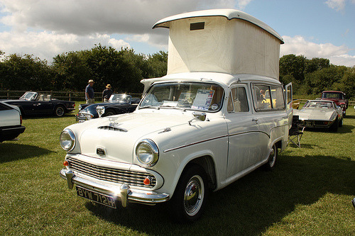
Vanagon – picking up a high top
Posted by albell in vanagon, vanagon mods on February 11, 2012
The start of Simon’s big adventure, a “Get-Away” hightop rescued from a decrepit ’82 Vanagon and taken to Simon’s place.


")
")
Novel fishing lure
Found amongst a large collection of fishing gear. The directions sure reflect the attitudes of the time it was made, guessing the ’70’s?


Lagonda convertible
Posted by albell in other cars on February 4, 2012
Need help, ’51 or ’52 or…?
Update: Identification made, 1952. Details of this particular car and history here.


Vanagon – wiper shaft lubrication
Seems like a slim subject for a post, but perhaps some of you don’t know it can be done. The shafts that stick out of the front of the van, and to which the wiper arms are attached, have a plain bearing sleeve. I bet that over time any lubrication in the sleeve is lost and the shaft gets that little bit harder to move.
I have a spare wiper assembly in the barn, so here are some pics of the shaft and housing.
Front view, showing the splined area that the arm meshes with, the threaded end for the wiper arm securing nut, the threaded base that the big nut that holds the housing in place on the sheet metal (the housing is also held to the van by phillips headed screws that you can see at the front edge of dash board near windscreen). You might be able to make out a circlip just above the large threads.

Circlip removed, 2 washers, and a rubber grease seal.

Back, inside view of above, circlip and washers removed and the shaft pushed back. This exposed shaft is what need lubed.

Make sense? Ok, out to the van. First pry off the plastic cap at the base of the wiper arm. See the little slot on wiper arm base where you can insert a screwdriver to twist off the cap?

Cap off, 10 mm nut exposed. Often it is pretty rusty in here.

Remove nut and thin washer, wiggle wiper arm and remove from stud. The splines will look cruddy like this one, no worry, clean the splines out with a pin/needle. It’s these splines which bite into the softer metal of the wiper arm that prevents the wiper arm from slipping, not how tight the 10 mm nut is. So spend some time to clean the splines out.

Pry off the black plastic shroud. Careful, don’t scratch the paint.

That big nut is supposed to be somewhat tight, 69 in. lbs (8 Nm). You can see the golden coloured circlip, remove that (don’t lose it!).
In this pic the circlip and the 2 washers have been removed, and the 10 mm nut put back on the shaft (to give me something to hold on to). The shaft was pushed in and out a little and that made the grease seal pop out.

Bentley says to use molybdenum disulphide grease on the shaft, I used gear oil. If I had the shafts right apart then grease would make sense, but seems to me that oil is better in this situation.

And then it is just a matter of putting it all back together. The circlip might be the hardest part to re-install. The wiper arm nut is tightened to 5 Nm (43 in. lbs). Do not over-tighten, risk of strippage! I place the arm on the shaft and before tightening the nut, I move the arm into proper resting position Then tighten the nut and the assembly draws up without moving out of position. Oh, and another thing, I glob some waterproof grease onto that nut to reduce rusting.
Vanagon – front door check strap
A few months ago my driver’s side door was allowed to swing open hard (van parked on hill, happened on this trip) and the check strap snapped. Got around to fixing it today. I had a spare assembly from my ’82, straightforward swap.
After the door card is removed, you can see the check strap assembly inside the door. The ’86 has a plastic cover over the works, the old ’82 did not.

Cover removed, two phillips head screws holds the mechanism on.

Removed and the broken end on the other side. The remainder of the strap, the part attached to the door jamb and held on with a pin and circlip arrangement was removed when I snapped the strap.

The replacement unit, and the waterproof grease I’ve been using recently for this and that. The stuff really does seem to resist washout better than regular grease (ie on shift linkage)

Installation is simple, no gotchas, here is pin on body end of strap.

Addendum: In the comment Jon asked if the check strap could be adjusted to give more resistance. I can’t see how that could be done, perhaps Jon’s mechanism is broken? Here are more pics of the “resisting elements”, the hard faced rubber bits that pinch the steel strap.


Vanagon – Jim’s sunvisor clip mod
Posted by albell in vanagon, vanagon mods on January 31, 2012
Another from the Felder Files©, modifying sunvisor clips on early (pre ’85?) to accept later model visors. I’ll let Jim explain:
“And please excuse the casual reference to “early vanagons.” The problem may
be limited to early Westies, but since I do not have an early non-westy
around to check, I”ll have to let you do that.
The main problem is that by now, the early-80s era sunvisors (which weren’t
all that great to begin with) have become sagging bags of foam dust. I have
tried everything I could think of to rebuild them. It’s a lot of work with
mixed success.
Online parts vendors stock them, but they tend to be for one side or the
other, not a set, don’t have a mirror where they should, and are hideously
expensive.
The world is full of very nice, late model padded visors in great shape. So
why can’t we use them?
The problem is easily noticed if you install them. The very end (near the
mirror) of the visor beyond the point where it snaps into the the visor
clip has just a little too much meat on it. Everything else lines up,
screws all fit, no mods needed, everything is nice–until you operate the
visor. When you do, you rotate the visor through almost 180 degrees,
thereby smashing that “meaty” part against the hardboard ceiling, and
levering off the top part of your clip in the process.
If you are handy with a hobby saw, and sandpaper, and have access to a set
of four clips that can be combined into two, you can have a very nice set
of late-model visors in your early vanagon. Did I mention that you could
have a lighted mirror on the passenger side?
I have pictures to send to those interested, but basically you take a clip
and an x-acto hobby saw and you saw the top (the part with the clip, sure,
you can used a broken clip for this) so you have a base with a flat top and
no clip. You take another one and saw off the clip as low as you can. You
glue the two together into a unit that looks like the original only about
1/4 inch taller. You sand the sides so that no excess glue show, and
install as usual.
Some may comment that it would be easier just to make a base out of some
plastic material that raises the unit, but if you get into it you will see
that there is a molded plastic tang on the bottom that fits into a square
locator hole where the clip goes. Unless you are prepared to recreate and
attach this tiny tang, you are better off with the procedure described
above.
It just works great. Time will tell if the epoxy has trouble sticking to
the plastic of the clip. I will report in due time.
In the first picture you can see more easily how the cuts were made. You can see the lip of overhang on the top piece that will be sawn off when the epoxy cures.
The second picture shows the piece trimmed and sanded, ready to install. ”


Hudson pickup
Posted by albell in other cars on January 27, 2012
Someone’s abandoned project

Here’s a shot of the engine. Doesn’t look like a Hudson L-head six, because it’s one of these.

Burns Night Supper
Tonight’s nod to tradition, haggis, mashed neeps and tatties. One slight alteration – for the first time in my life I baked the haggis instead of simmering it.
Och, its just a wean.

The tatties, cup-up neeps (swede/rutabaga), and the poor wee thing. Och, I just remembered calling neeps, tumshies when I was a bairn.

After about an hour at 400 F (haggis was wrapped in foil)

I’m sold on this method, even before tasting.

The full meal deal.

A confession, I like HP sauce with my haggis.
ATA – snow
Posted by albell in aircraft, around the airport on January 18, 2012
Our yearly snow event, chased all the planes away.

So, which one is closest to your reality?
Posted by albell in other cars on January 17, 2012
Saddle Tramps continues to post interesting campers. The juxtaposition of these two vehicles made me think about fantasy and reality.

Vanagon – syncro front diff. input seal replacement
Posted by albell in syncro, syncro specific repairs, vanagon on January 13, 2012
Back in October last year, when I had the front diff. out to install a new VC, I noticed that the input seal was leaking. It would have been smart to replace it then, but I couldn’t wait for the seal to be ordered in. Then I procrastinated, put the job off until today. The job is quite straightforward; disconnnect the prop shaft from the front diff., undo the 24 mm nut that holds the drive flange on the input shaft, remove flange, remove seal, replace seal, replace flange, etc.
Addendum: Have a look at this thread on Yahoo Syncro list for discussion on cheaper seal. I didn’t see that thread before I bought the expensive one from dealer.
I’ll be pedantic and list the steps I took:
– chock pass. side wheels and jack and support driver’s side so that left rear wheel is off ground (you could have both wheels that side off the ground, would be easier to rotate propshaft to get at all the propshaft flange bolts)
– loosen the 3 bolts (17 mm) on the rubber mounts on front diff.
– mark the propshaft flange, the front diff. flange, and the front diff so that you can get all the bits back in same orientation.
– remove the 4 nuts and bolts holding propshaft to front diff. flange (13mm, use 2 open end wrenches), and let the propshaft rest on ground, or support with wire.
– rig up some sort of tool to hold the flange as you undo the nut (24 mm), the nut is on there tight (135 ftlb). My elegantly engineered (ha!) flange holding tool required the pass. side propshaft protection rail to be lowered a tad.
– a 2 arm puller to pull the flange off the shaft, came off very easily.
– the exposed seal can be pried out with a strong screwdriver. I was surprised at how secure it was in there. Be careful not to damage the aluminum housing.
– some oil will drip out, have a container in place to catch it
– new seal is lubed then, as the Brits say, offered up to the housing. I used a brake caliper piston to carefully drive the seal home.
– then the flange, and the washer and nut. Again you need to hold the flange as you tighten the nut.
– propshaft back up and secured.
– some gear oil squirted in the fill hole (17 mm socket head plug) just back of the driver’s side inboard cv joint.
– the diff mount bolts left loose for a few miles, then tightened up. Just to allow the front diff to settle in a happy place (a sort of horizontal self alignment).
Addendum: overview of area. 26 = 24 mm nut, 25 = thick washer, 24 = input flange, 23 = seal (22 = circlip and 20 = bearing. Both un-involved with this repair)

Here are some pics:
See the oil splash?

Propshaft removed, the 24 mm nut that holds the input flange on is revealed.

Flange held firm using homemade tool, nut loosened.

Flange off, seal exposed.

Shots of how the brake caliper piston is a good fit to use as seal seating tool.


New seal installed.

Vanagon – silliest toaster ever
Posted by albell in metalworking, vanagon, vanagon mods on January 13, 2012
Fever dream realised with some scrap aluminum tubing and some stainless steel mesh. Space efficiency? We don’t need no steenkin’ space efficiency.


ATA – more Alphajets
Posted by albell in aircraft, around the airport on January 9, 2012
One in interesting colours.

Beached
Phil Z. took this pic, somewhere near Campbell River.

Pintle hitch
I bought 2 of these at a government auction a few years ago. Gave one away and managed to bury the remainder under junk in the “workshop”. I wonder if I can machine an adapter so that it can fit in a regular receiver and retain the rotation feature. Just for no other reason than it looks cool.


2011 in review
The WordPress.com stats helper monkeys prepared a 2011 annual report for this blog.
Here’s an excerpt:
The concert hall at the Syndey Opera House holds 2,700 people. This blog was viewed about 55,000 times in 2011. If it were a concert at Sydney Opera House, it would take about 20 sold-out performances for that many people to see it.
Vanagon – rear defogger grid repair
A really minor Vanagon repair here. Recently my rear defogger quit working and it turned out to be a broken wire in the area on the driver’s side of the rear hatch where the wire comes out of the body and into the hatch. Same thing can happen to the wires that power the rear wiper on the other side of the hatch. Once that was fixed I noticed that one of the grid lines was not working (condensation was slow to evaporate from one section). A closer look revealed a section of the grid that was scraped off.

I had an old repair kit in my pile of junk. All it is, I think, is copper powder in a fast drying resin/solvent mix.

Years ago I had done the same repair on my old ’72 Westy and I used the supplied template. I found out then that the slit in the template is way too wide, so I added some masking tape this time.

I applied the paint, a couple of coats, and left it overnight to dry. It worked, the grid conductivity was restored. But when I pulled the template off the paint came with it. So I re-did it but pulled the template off when the paint was wet. Here is the result, not perfect (I might try using a razor blade to clean it up a bit), but it works.

Vanagon – LED dash/control lights – commercial improvement?
Posted by albell in vanagon, vanagon mods on December 19, 2011
You know how I have complained that the beam pattern from my home made and Van Cafe sourced LED gauge cluster bulbs is not optimal. The “standard” type LED projects most of the light through the end of the diode, and even if you grind the end of the diode at an angle, or have ones that are flat ended (Van Cafe) it does not improve the beam dispersion that well. The stock incandescent bulbs project light from the sides as well as the end, and the bulb holders are designed to take advantage of that.
Well it seems that Go Westy are selling LED bubs that might address this problem. The heater control light looks like it has SMD units on the sides in addition to one on the tip. This should really make a difference. But jeez, expensive little buggers eh?
Go-Westy’s cluster bulbs do not have side mounted LEDs but appear to use a SMD unit. My limited experience with SMD LEDs makes me think that they have a much wider beam dispersion than the bog standard LED.
I have not tried any of Go-Westy’s LED so I am speculating based on the pictures.
Addendum: I’m remiss in not thanking Tom for the head’s up on the Go Westy bulbs. Also, I don’t want to appear to be endorsing Go-Westy’s stuff, I am not getting any kick-backs, sadly 🙂
At the wreckers – sample of JDM vehicles
Posted by albell in other cars on December 9, 2011
I concentrated on vans, but there are a few SUV types there too.
ATA – December 8 2011
Posted by albell in aircraft, around the airport on December 8, 2011
Maybe Angus will ID the jets? Update: he did – Challenger 604 on the right, and probably a Gulfstream G450 on the left.
A shot of another VIH Kamov here.

A couple of miniatures
Made back in the ’50’s, couple of examples of the early work of a long lost relative of mine. The pistol seems to be chambered for a .22 cal cartridge, a blank of course. The hammer cocks and the trigger and guard act as trigger.


Vanagon – digital clock LED light improvement
Posted by albell in vanagon, vanagon mods on December 7, 2011
Quick mod to improve the lighting of the digital dash clock. I replaced all of the incandescent lights in the dash with LEDs some time ago, but you know how the light dispersion on a LED is much more restricted than that of an incandescent and it really is apparent in the digital clock. This German fellow thought the same and went to some trouble to fix things. I tried one of the hacks he discounted – installing some reflective material.
Clock apart, some adhesive backed aluminized foil stuck in to reflect the LED output to the 2 light pipes on each side of the clock face.

Clock back together, you can just make out the led close to the peak of the mylar foil.

And how it looks installed. Notice how bright the tach and speedo faces are at the top? I had put some of the same foil in the light housings hoping it might improve the light from the LEDs up there, but it seems to have just accentuated the poor beam pattern. Camera setting does make it seem worse than it is in reality.

Also not that the little black shade is missing, or slipped, from the tach light housing. Here is the housing with foil.

Still more work to be done with this idea.
Vanagon – syncro viscous coupling anatomy – part 2a
Some more images of the slots on the slotted plates of the VC. Any burr or ridge is not so clear, but perhaps there is one on the worn side of the plate. The series show the same plate, un-worn, then worn side. Clicking on the pics will bring up larger version.
Un-worn side.

Worn side.

Un-worn side.

Worn side.

Vanagon – syncro viscous coupling anatomy – part 2
I took some pics (btw, all the pics can be clicked on to get larger image) of the plates in an attempt to see those “burrs” on the holes or slots that are implicated in the hump or STA (self torque amplification) event. I think having my sketch diagram of how the plates and spacers are arranged would be useful here:

Here is the stack as it comes out of the VC. Note that the circlip and shims are not on the end of the shaft. Also note that the top plate is not held in the stack by the circlip, but rather is pressed against the endplate when installed.

The reverse side of that top plate, obviously worn.

And the slotted plate below.

Now remember, these two top plates are not spaced apart. The next plate however, is spaced from the slotted plate you see by approx. 0.025″. Mis-focused on this pic, but included it to keep the arrangement clear. See the wear on it even though it is spaced from the plate above?

Here, with the above plate beside, slotted plate turned over.

Closer view.

Here are the adjacent surfaces of another pair, same arrangement as the worn pair above, ie has spacer separating them. Note that they are not worn.

Now lets get a better look at the punched holes.

Closer, I’d say there was a raised rim, very subtle.

And a shot of worn plate holes. I think you can see where the rim/burr whatever you want to call it has been worn.

I only had time to get one close up of the slots in the other plate type, no rim evident on this side at least.

Well, this exercise demonstrated, to me at least, that there are burrs on the punched holes. As to the role of these burrs, I will deal with that in part 3.
ATA – Nanchang CJ-6
Posted by albell in aircraft, around the airport on December 2, 2011
Got a couple of quick snaps of one of the local Nanchamg CJ-6‘s taxiing today. From the reg. # it is a CJ-6a.


AAA – around another airport
Posted by albell in aircraft, around the airport on November 26, 2011
Congratulations to fellow Vanagon mailing listmember Frank G. on the successful launch of the Curiosity Rover. Frank sent these pics:


