Archive for category vanagon
Vanagon – radiator replacement (mine)
Posted by albell in syncro, syncro specific repairs, vanagon on June 21, 2012
Not really much to add to the previous rad replacement expect that it is my van (’86 syncro) and I thought I’d make it a post just for my documentation/memory aid purposes. I suspected my rad needed replacement for no other reasons than I think it is the original rad and that I noticed the rad fan coming on more often when idling after a hwy drive. The replacement is a Behr unit, made in South Africa. The old rad still had the a/c condensor rad attached in front, probably not helping heat escapement. The new rad did feel lighter than the old one, whether this is due to deposits in old rad or construction details I can’t say. No real details to note except that it is a pretty easy job. I clamped off the coolant lines so a total coolant replacement was not done, I glued on the little rubber washers on the spikes on top and bottom of the rad (so that they didn’t fall off during installation, and I sprayed Fluid Film on exposed fasteners in the general area. After install and bleeding, I have only idled van long enough (took 20 minutes) to get first stage of fan to come on, no road test yet.


Vanagon – GoWesty Wasserstopper rain fly hook issue resolved
Posted by albell in vanagon, vanagon mods on June 8, 2012
I received replacement hooks from GoWesty for the Wasserstopper rain fly. I had complained that original hooks held on to the gutter poorly. Good customer service!
The replacements do hook on to the rain gutter much more securely, but I haven’t had the chance to fully test with them attached to fly.
My best pic of original hooks, they end up hanging on by fingernails.

Replacement hook.


Vanagon – that transmission noise fixed?
Posted by albell in syncro, syncro specific repairs, vanagon on June 7, 2012
I’m just back from test drive after installing my re-bushed propshaft and I can report that the noise I was hearing, and that I had thought was transmission noise, has gone! I’m chuffed!
But to ward off the Evil Eye, I’ll not claim victory.

Vanagon – making new syncro propshaft internal bushings – Part 2
Posted by albell in syncro, syncro specific repairs, vanagon on June 6, 2012
I decided to make a split bushing for the internal location. I first turned down some Delrin to final inner diameter (23 mm to match the turned down yoke shaft), then mounted it on a mandrel to turn down OD to 28 mm (was OD of upper bushing and I guessed that the inner one was the same).


I kept the bushing on the mandrel and clamped it in my wee milling head. I also used a small C-clamp on the bushing to stop it from popping off during slot cutting. I used a 1/8″ end mill to cut the slot, made the slot 6.8 mm wide (chord length) which I estimated to be slightly more than needed.

Finished split bushing.

And as I tried to install it, I realized I had no way of holding it compressed to get into the narrow bore, no grip after it goes into outer bushing area. Oh, btw, this is how the bushing should appear when it is finally in place at the bottom of the housing.

I had an idea, some stainless shim stock to act like a funnel.

That worked and I was able to tap the bushing home. You can make it out, down at the bottom.

The yoke shaft would not fit in, I had to chamfer the end of the shaft a little more, and polish the end. But I finally was able to tap the shaft in and it is nice and snug. Quite snug actually, it takes about 20 Nm to rotate the yoke, but no radial movement at all. Oh and another thing, I removed that flange on the upper bushing, didn’t make any sense. I’m feeling quite chuffed in managing to get some sort of bushing replacement made. I hope they will wear well.

Vanagon – making new syncro propshaft internal bushings – Part one
Posted by albell in syncro specific repairs, vanagon, vanagon mods on June 6, 2012
I have my propshaft off while I try and track down my transmission noise (see previous post). Some helpful syncro owners over on the IG16 forum suggested that I look at my propshaft as the source of the noise. Well why not eh?
This is a story of mistakes and ignorance. When I compared my two propshafts in this post, I mistakenly concluded that one shaft had thinner walled bushings than the other. Well it did look that way and both assemblies felt equally tight – ie acceptable fit of shaft into bushings. But I think I must have been wrong for when I examined the “thin walled bushing” propshaft (the one I just removed from van), I could detect play in the bushings. The rubber giubo and the internal O-ring have been removed and dial indicator set up to measure movement as I lifted U-joint yoke up (trying not to rotate joint as I did it).
Here is diagram of that end of the propshaft just to refresh memories.

And my measurement set-up.

And short movie showing movement.
I admit to this being not an extremely accurate way of measuring the radial play, was hard to just move the yoke up and down and not rotate it. But I could feel the play and it was more than I think it should be.
So it comes down to replacing the bushings. The outer one would be relatively easy, but the inner one is a different story. And I think the inner one is important to be snug as it is at the end of the shaft and would limit shaft movement more than the outer bushing. That was a convoluted sentence, I hope you get the idea.
On the Yahoo Vanagon Syncro mailing list, the bushings have been discussed a few times. One list member wrote (a year ago?) that the inner bearing could not be replaced as it sits in a recess in the tube and was probably installed before that end was welded onto the propshaft. The drawing at top of this post does not really show the recess (drawing too small), and I had forgotten all about it.
Foolhardy is a useful adverb to use whenever I get it into my head to fix something. I kid myself that I know what I am doing, ha!
I pondered how to remove the inner bushing and came up with chiseling it out. I have this neat little 1/4″ chisel that looked like it would work.


And off I went, chiseling a groove down the inner bushing. It took a couple of groove before I could break out the bushing. I found it difficult to get a good pic of what was going on deep in there, but in this pic you can see a section of the bushing folded inwards. Sharp eyed readers will be able to see that there is a lip in the tube which locates the bushing. Bushing was pressed in from other side, then that end cap inserted (portion of bushing is obscuring the hole in the center of that end cap), and then assembly welded to propshaft. Even sharper eyed readers will notice another, smaller lip about halfway between inner and outer bushings. I overlooked this, I have no excuses why and it bit me on the ass later on.

Bits and pieces of the bushing. After I knocked the fragments out I could see the aforementioned lip. I didn’t feel very happy at that point.

I really had no choice but to go on and cut out the outer bushing. This pic shows how well the chisel cuts the bushing and the underlying steel – doh!

Note the fretting or corrosion on the surface of the bushing. Here is a close up of a fragment, looks a bit like sintered bronze, like an “Oilite” plain bearing.

So alright then, what to do about the inner bushing problem? I wasn’t about to cut the end off the propshaft. I settled on the idea of turning down the diameter of the end of shaft a tad, to about 23 mm from 25 mm (diameter at end where shaft inserts into bushing) and making that reduced diameter area about twice as long as the original bearing surface. I reasoned that a Delrin bushing could be made to fit into tube, be supported by the tube and extending on unsupported over the original bushing spot. Jeez, I need a diagram to explain.
Here is a cartoon cross-section of the end of propshaft that houses the bushings.

And with shaft in place.

Modified shaft.

And assembled with new bushings.

The drawings are not to scale and are meant just as sketches to get my idea across. Important thing to note is the new internal bushing will come further up the shaft, and be unsupported in old bushing area.
Off to the lathe!
Mounted yoke shaft between centers, was lucky and set up resulted in less than 0.001″ run out at end (inner bushing area).

Then turned the end down to 23.00 mm. I found it hard to get a nice surface finish even with very light cuts. I was using a round nosed HSS tool bit (has given me nice finish on other jobs), but this time I had problems. So, a less than perfect finish.

Chamfered the end and gave it a quick polish. I think it will be good enough.

Next step is to make the Delrin bushings. Whoa, slow down sonny! Have another look inside the propshaft, it is not quite the same as you describe in your sketches. Go on, look at that picture you took of the bore. What? No! Really? , let me… well gosh darn it.

I missed this before I thoroughly cleaned out the bore – the bore is machined out slightly for a little way, above the machined out area for the internal bushing. Illustrated, but exaggerated and not to scale, the slightly bored out region is not as large a diameter as illustrated, but it still screws things up for me.

So my original plan of a longer internal bushing will not work, see?

I decided to make the outer bushing, classic avoidance behaviour. I actually made 2 outer bushings, first one really as a practice piece, second one with a lip. I also went ahead and, again for practice, made the now discarded inner bushing concept.
Delrin rod (1.5″ diameter but turned down a tad before this shot) and boring out to fit yoke shaft. Gotta love that chipped cutter I am using, funny thing is that it does a nice job on this plastic.

Bored out to size, 25.00 mm.

I made a quick and dirty mandrel to mount bushing so that the outside diameter could be turned to size.

Then to get the bushing off the mandrel, I bored out the end of the mandrel.

To make the “practice” inner bushing, I first bored out Delrin to size, parted off, then mounted oversized bushing to yoke shaft to machine down to size. Note the outer bearing installed first. Makes you wonder if I hadn’t realized the issue with the propshaft bore yet, doesn’t it?


As I mentioned before, I went on to make another outer bushing and gave up for the evening.

Back to the problem of, in essence, installing a bushing from the wrong end. How about making the bushing the squeezing it to deform enough to be pushed in the bore and end up in position, then use a tool to form it back into shape, against wall of bore? Nope, daft. Well how about taking propshaft to machinist to bore out? Well, that might be the fall back solution. Ok, how about a split bushing? Would that allow the bushing OD to be reduced enough to be pushed in and then expand in correct place? Mmm, maybe, worth a try?
Something like the Iglide Clip2 plastic bushing (but without the end flange)?

The nominal diameter of the bore is 26 mm, and where the internal bushing is located, 28 mm. Circumference of bushing should be (pi X 28) 87.96 mm, and to fit in through 26 mm bore, 81.68 mm. So slot in bushing needs to be at least (87.96 – 81.68) 6.28 mm. Seems like a large slot to be cut. One thing in my favour is that the yoke shaft does not fully rotate in the bushing, just a few degrees allowed by the flex in the Giubo. A diagonal slot as shown in the Iglide bushing above would provide better support of the shaft so it is worth a try cutting the slot that way.
This post is getting rather long and rambling and I have other work to do, I’ll try making the split bushing later and report back in another blog entry. Feel free to give me a hard time in the comments section, I deserve it 🙂
Vanagon – trying some things to make the GoWesty rainfly work a little better
Posted by albell in vanagon, vanagon mods on May 26, 2012
UPDATE – 29/05/2012 – I posted my attempts at fixing the gutter clip/angle/hook issue on the Samba and a member responded that there may have been a mistake made at Go Westy with wrong hooks being sent out. So I emailed Go Westy, outlining the issue and I got a quick response of new hooks to be sent out to me. I am impressed by this prompt customer service, well done Go Westy.
I spent a couple of hours playing around with the fly, wanting to fix- what I see as problems – the gutter angles/hooks and the front strap system. Previous post about fly here.
I’m just using what I had on hand, and this is only preliminary stuff.
I had some longer metal hold down hooks, I sewed some velcro on to them. These hooks have a more obtuse angle on them compared to the Go Westy ones. I also attached some webbing attached hooks and buckle for the front straps. I added some silicone tape wrap to those hooks.

The new angles are longer, so I stuck on some velcro to the clip itself to provide a bit more area of velcrotude.


The new angles/clips do seem to hold on firmer.

Where my ShadyBoy awning is, I left the stock hooks, they are fed up from below and the hook part can’t pass through the space. I was dumb not to see this way before, I said in my previous post about the fly that it was not possible to attach these hooks, doh.

The front strap mod is not so successful, but not completely ass.


An annoying curl in the material at the front.

Well, it is a start, I’ll be trying to get it a little better. I’m not happy with the front strap idea.
Simon’s hightop – installed and off on a trip
Weekend before last, the hightop was installed on Simon’s ’91 syncro westy. Late night and quickly thrown together video of install.
And then this last weekend he took it on a trip.


Inside is insulated and carpeted, but side cupboards and little details still need to be installed.


Big difference from the start.
Overnighter NW of Port Renfrew
We grabbed the chance to do a little exploring on the south end of the island (Vancouver Island), specifically just northwest of Port Renfrew. The area you get to if you hang a left instead of a right after the high bridge over the Gordon River.
Typical, secondary and not heavily used logging road.


Further on, around 680 meters elevation, some old growth but mostly second growth (guessing old growth cut in the 60’s-70’s, perhaps later). Lots of Yellow Cedar, one down across road but a section at end cut and easily moved to get past (yes, patch of snow there).


And found a nice viewpoint to camp.

Olympic Peninsula (USA) in the distance, Cape Flattery on extreme right.

Like a bad haircut, or having a hightop on the van, the campsite was fine looking out, not so bucolic looking in. Still, no one around and plenty of firewood (felt like a millionaire burning Yellow Cedar, the scent is divine).


Tired dogs.


A couple of little lakes close by, here is a glimpse of one.

The clouds and rain moved in next day.

The “Excelsior” proved its worth at breakfast time.

Typical view when rain comes, looking north east.

We spent the wet day exploring the roads a little, but the low cloud made it a silly exercise. couldn’t see much. Headed back home via long loop up via Gordon River watershed and Cowichan valley (some pics of Gordon River area in this post). All in all a great little trip.
Oh, forgot to include one of those “same place, different time” shots. Side road on Gordon Main (TR4 I think), again on slash, where my son and I camped overnight while exploring region last year.
Then:

And now:

Addendum: I was asked about pressure cooker beside “The Excelsior”. It is my EKCO model I use winter camping and in the van, had it for 30+ years. I bought it second hand and it seems the model at least, dates from the ’40’s. Found an ad at this site.

Vanagon – coolant temp sender wire repair and another broken hose
Posted by albell in syncro specific repairs, vanagon on April 24, 2012
Is it good or bad luck I am having?
About the same time I discovered that leaking coolant hose I mentioned in this post, I noticed that my coolant temp gauge was not working – no needle movement nor did the warning LED flash upon start-up. I had been mucking around with the cluster a fair bit and I thought that I had either broken the circuit foil or had a bad connection at T14. But examining the dash did not reveal any problems. I finally tracked it down to a bad connection at the female spade connection to the temp sender back on the thermostat housing. The insulation on the wire was very brittle for about 2″ up from the spade, and the connector itself felt a little limp on the wire. It has been worked on before, that is not a stock spade connector.

The copper was corroded, and you can see the discoloured insulation which pretty well corresponds to the brittle section.

I cut back the wire to where it was flexible and spliced in a new length, plus a new spade connector (section of plastic insulation was cut out to allow the spade to slip on the temp sender).

Here is the brilliant location of the temp sender, exposed to heat and road splash.

And the new connection made.

So after that I was mucking around looking at things in the engine compartment, engine running, when I pushed on the hose that runs from the upper coolant crossover tube to the narrow steel tube that runs around 3 sides of the engine compartment. The hose split and coolant rapidly spat out. Yes, that is steam in the picture.

Te previous owner had used fuel line hose, and it was hard and brittle.

I had some spare hose to make the repair, and I think my van is really trying to tell me to go over all of the hoses and replace. I got the message with the previous leak, but nothing like another nudge in the ribs.
Vanagon – eccentric stub axle?
Posted by albell in syncro, syncro specific repairs, vanagon on April 22, 2012
(note: holding stub axle by the splines was an error duly pointed out by David in the comments. Axle re-measured and post updated.)
I was complaining to Phil Z. about my wheel bearing failure and he suggested I have a look at the stub axle. So I chucked it up on the lathe, holding it by the splined outboard end (was careful to have the chuck jaws positioned correctly on the splines) and then I measured a couple of things.
Where the outboard bearing seats had 0.009″ runout.

At the inboard bearing seat I measured 0.015″ runout (sorry, fuzzy pic slipped past me).

Where the seal rides, 0.020″.

The face where the CV joint mates had 0.010″ runout.

I did not measure that outer edge of the CV mounting flange as I thought eccentricity there was not important as the cv is aligned by the bolts.
And here is a quick vid of the assembly spinning.
What does all this mean? How does a new stub axle measure up? Was this runout the cause of my bearing failure?
Addendum: Crow eating time. David’s points about where I was grabbing the axle (splines) was correct. I re-measured runout with axle held by outer bearing seat.
Runout at inner bearing about 0.005″.

At seal, 0.007″.

Flange face, 0.002″.

Looks a lot better in motion.
So there, no smoking gun after all.
Vanagon – cooling system leak
Posted by albell in syncro, syncro specific repairs, vanagon on April 20, 2012
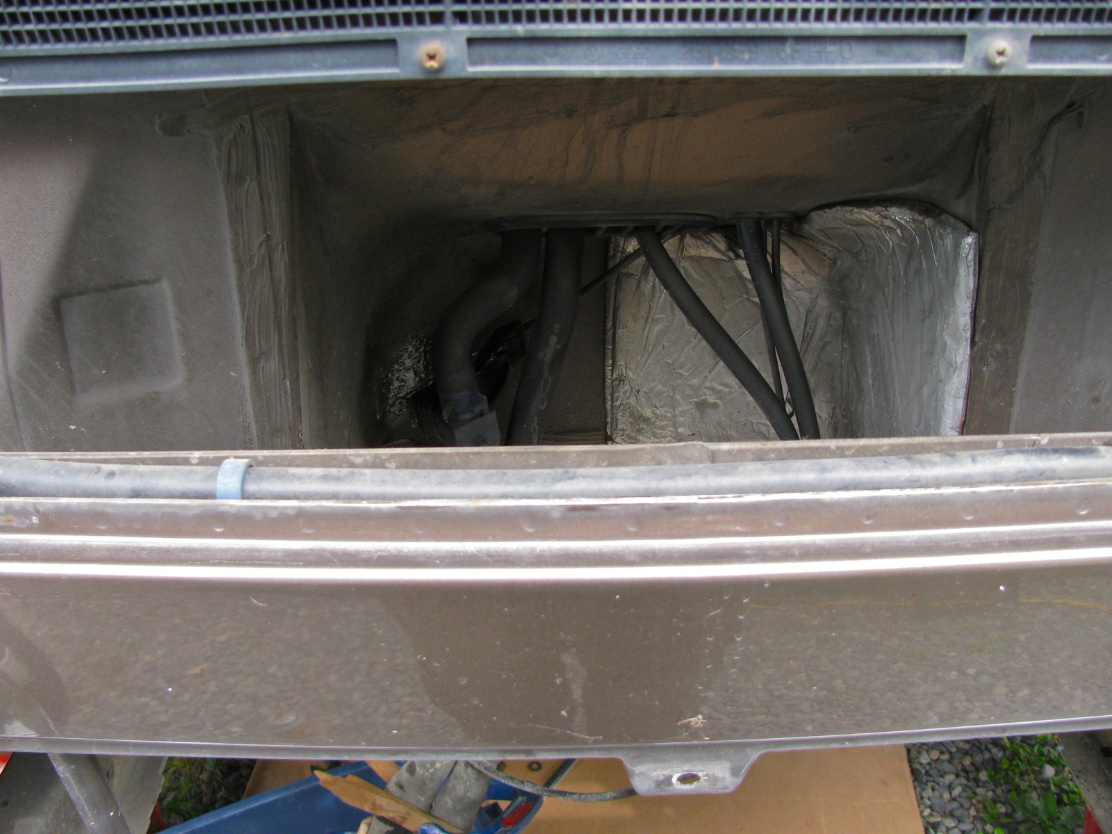
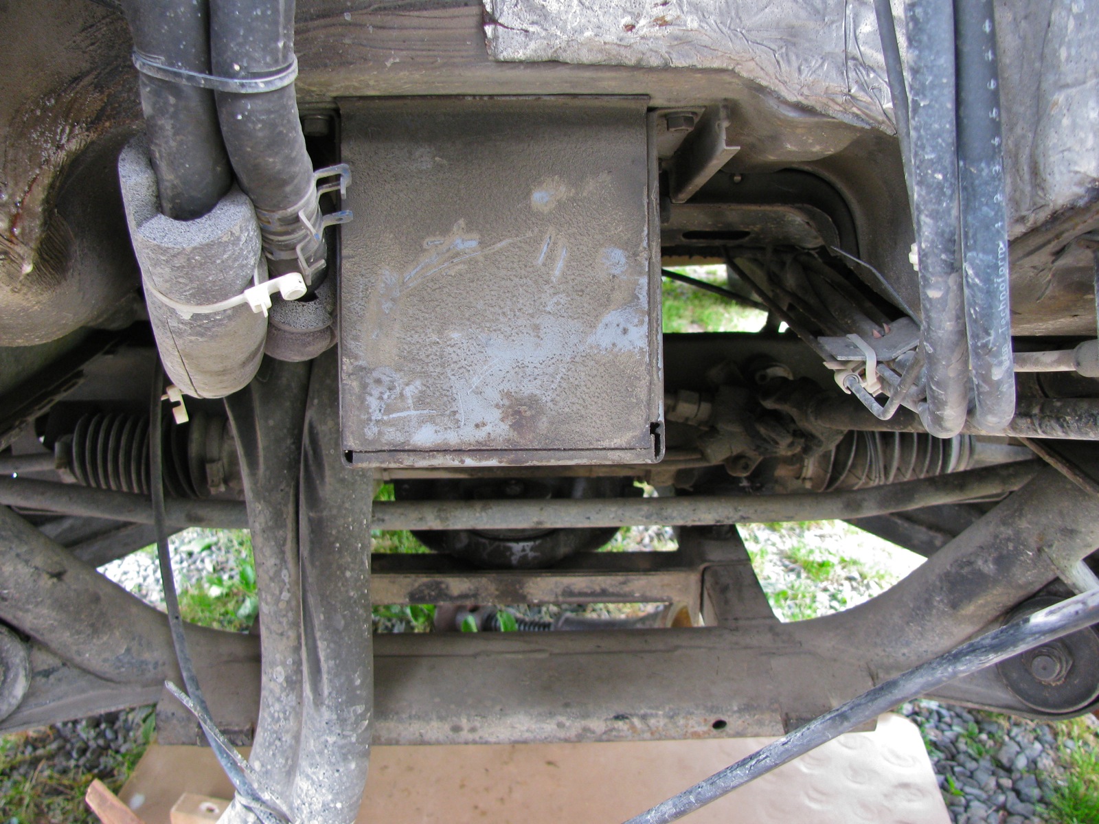
Bloody vans eh? No sooner than I fixed that wheel bearing than another problem bites me. Last couple of days I had been noticing a slight whiff of coolant when I got out of the van. I couldn’t see any leaks, inside or out. Then yesterday I noticed that my coolant overflow tank was empty and even I could not ignore the fact that I had a real live leak somewhere. I topped up the tank and fretted about expensive repairs. Today after a short drive, the smell was much more pronounced and I did find the leak. Thank the Vanagon gods that it was a hose leak, short section that runs from the thermostat to the lower of the two crossover pipes at the front end of the engine.
This pic from above does not show any wetness (the bad hose is the lower, thick one). Update: I think it is this hose featured at Van Cafe.

But from below, you can see the marks of a leak.


I had to remove a bracket that holds the remnants of the Webasto coolant heater system to get at the short hose, and remove the bell housing vent to get it out of harm’s way (syncro bell housings are sealed to the motor and a vent is provided that leads up somewhere above the gas tank). No surprise I suppose when I broke the plastic elbow when removing the bracket, so it goes.

With the bracket out of the way, I could get at the hose. Off it came and time to look at it closely.

Just a pinhole really, but big enough to piss away 1 litre of coolant in about 30 minutes of driving. I had some used hose that I took the chance with, and I got it back in place. I had a closer look at the broken vent elbow, it was plugged solid with some sort of crap.


Then I made a jury rigged repair to the vent elbow using some silicone tubing, stainless tubing, and a bit of stainless wire wrap.

Yeah, I know, this hose leak is a not so gentle reminder that all of the cooling hoses on the van are old and tired. The thing is, I have it in mind to swap in a different motor so I’m being a bit cavalier with this old wasserboxer.
Vanagon – getting that 46 mm wheel nut off
It occurred to me that I should have mentioned how I removed the 46 mm castellated wheel nut off the rear wheel in the last post about the bearing failure. The nut is on there good and tight, Bentley says to torque it up to 360 ft lbs (for the 10 slot castellated nut, the older 6 slot nut was torqued to a lesser value, something like 285 ft lbs). I don’t have the heavy duty air tools that would handle this but I do have a 3/4″ drive, imperial socket that fits (1 13/16″ – handy metric to fractional imperial chart here), corresponding tommy bar, and a 3 ft section of thick walled steel pipe. You can apply a lot of twist with this set up and can even get a fairly good idea of torque applied if you know your weight and where about on the pipe you are applying it. You know the drill, 100 lbs of weight one foot from the axis of rotation is 100 ft lbs, same weight two feet out is 200 ft lbs. You loosen the nut before you jack up the van, and have the handbrake on. But the other day when I was doing the bearing job I had a dickens of a time getting the nut off without the wheel turning and the van moving, and it was impossible to loosen the nut on my parts van as the transmission is out and the free end of the axle was just hanging in space. I did try the slug wrench mentioned in my original post on wheel bearing replacement, but it did not budge the nut.
So how do you stop the wheel from turning when you are grunting down on the end of the 3 ft extension? Well, you have to jack van up and support it securely on good jackstands. Remove the wheel, and use the lug nuts to secure some sort of metal bar to the brake drum. I have lots of scrap bits of aluminium around, so I used some 1/8″ 3/16″ thick angle. The angle bears on the ground stopping the hub from turning. Here is a snap taken today when I pulled the drum and hub off the other rear wheel to have a look at the brakes. Not very clear in the pic, but there are 2 lug nuts holding the angle to the drum. Note also the old house jack supporting the socket extension.

This really worked, no drama, no movement of the van. Used the same technique when tightening the nut.
Oh and here is what I wanted to look at. With the hub out of the way I could see the gubbins clearly and I wanted to be sure all the brake springs were installed correctly (I *think* they are). Plus I wanted to pull off the threaded adjustment bar and clean it up so that it would actually adjust (I hate the Vanagon rear brakes).

Vanagon – rear wheel bearing redux
Almost exactly a year back I replaced the bearings in right rear wheel, but a couple of days ago I noticed some play in that wheel. I thought more play than there should be (i.e. none to a teensy amount). So I pulled the bearing housing and this time taking the driveshaft and CV joints with it. That meant CV joint to transaxle connection detached. I had a spare assembly, all greased up and ready to go, was from my old ’82 westy and still ok.

Got it installed ok, never really a fun job. Then I had a look at the one year old rebuild. I had the notion that maybe the bearings might be loose in the bearing housings, but no, they had to be driven out with some effort. The outer bearing looked fine, but the inboard bearing looks discoloured.

And it feels slightly rough when spun. So what’s the story? Did I not lube it enough during install? This picture from then looks like I did not put much grease into the bearing, but what you see is the stuff I had smooshed into the bearing, more lube was put on after the bearing was in place.

Maybe I did screw up, wouldn’t be the first time.
Update: looking at the bearing again, I’m not so sure it overheated. It looks more like corrosion on the outside of the outer race. Still puzzling.
Addendum: I cleaned up the CV joints on the axle I removed and one joint is ok, the other is on its way out. I have to admit that I had not serviced the rear CVs since I bought this van a couple of years ago, it really should have been done. The grease was a bit dry on both joints, and one showed signs of impending failure (Ed. jeez, that sounds a bit over dramatic).
Outer race removed.

Expected and acceptable wear.

One of these balls is not like the other ones.

Inner race, would this erosion spread?

You kinda wonder if tri-annual repacking of CV joints is the way to go, or just replace them every seven years or so. It is a bit of a chore getting the axles off, and more of a chore cleaning and repacking. CV joints are about 90 bucks a piece here, I don’t know what is the best strategy.
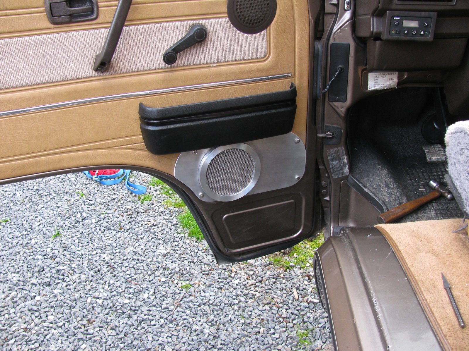
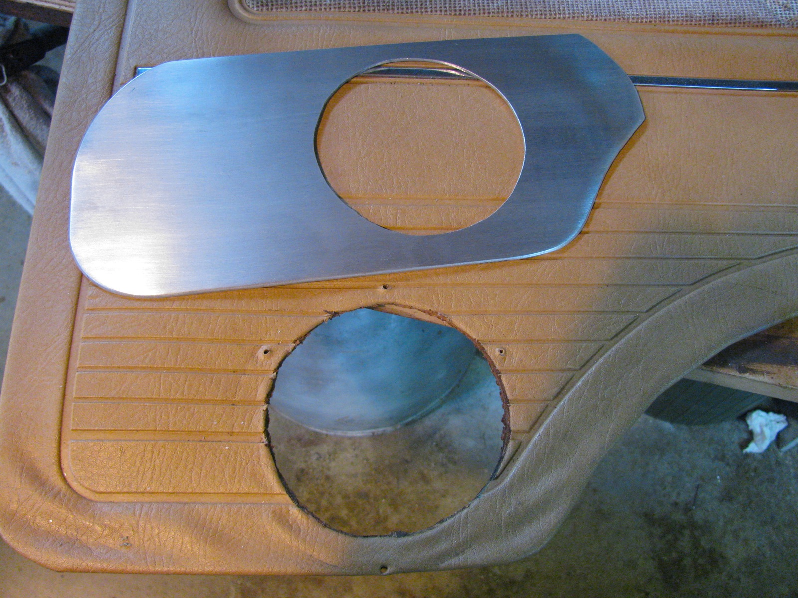
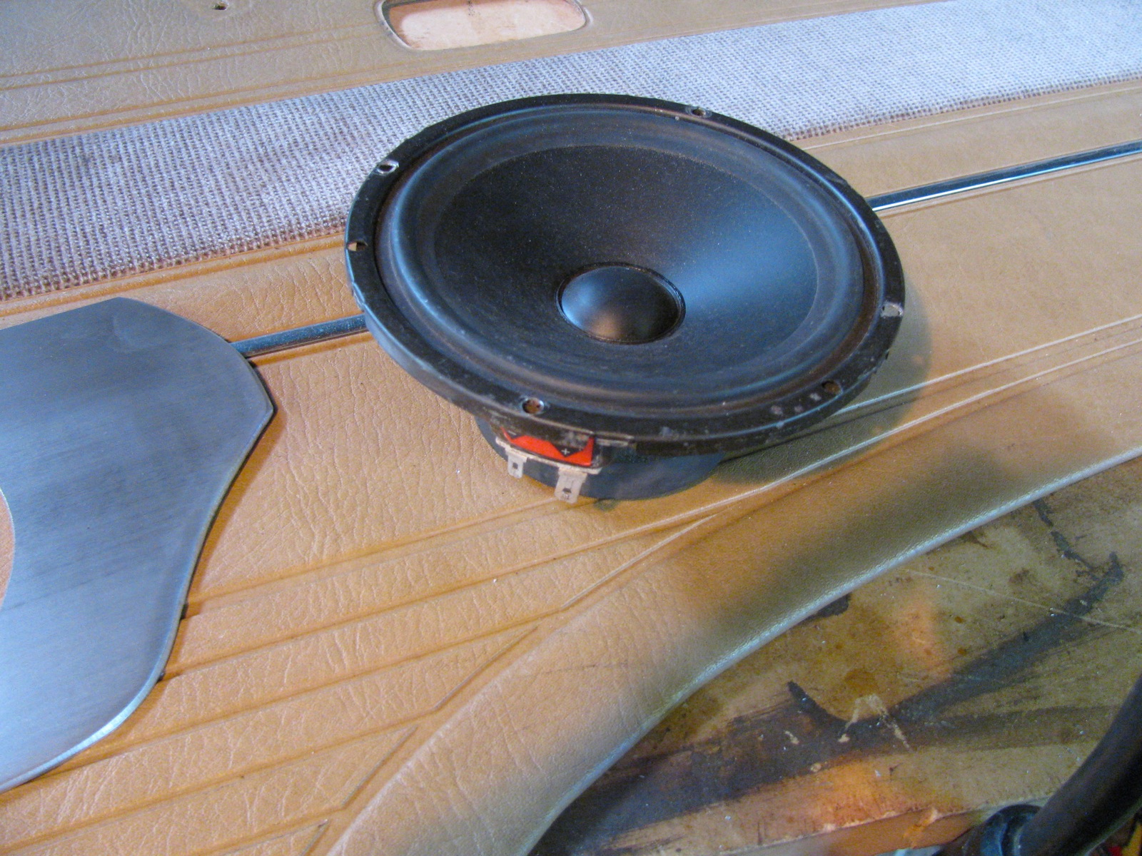
Vanagon – front door speaker mounts
Posted by albell in vanagon, vanagon mods on April 5, 2012
Update: I painted the mounts and grill. Blog post here. I think the paint holds the grill mesh in a dome shape better than no paint.
The door cards on my ’86 syncro were falling apart down where the previous owner had installed 6″ Boston Acoustics speakers. Really, the entire door card is pretty tired and warped but I chose to just do a quick and dirty reinforcement around the speakers. I used some scrap 1/8″ aluminium sheet to cut out a plate to stiffen the bottom of the card, some 1/2″ plate was turned down to make new bezels for the speakers, and some stainless steel mesh to make new grills.
It turned out more rugged utilitarian looking than elegant, but much better than before. Oh btw, there are tweeters behind the stock speaker grills up higher on the door. The crossovers are tucked up under the dash.

Vanagon – VW pop top insulation
Posted by albell in syncro, vanagon, vanagon mods on February 13, 2012
Borrowed from good friend Simon, this genuine accessory is supposed to be installed outside the pop top but with the rain fly on, I thought I’d see if it was able to be installed inside. A little bit of a wrestling match, but it goes in and stands up by itself. Hey, notice I still haven’t installed an upper bunk.


Vanagon – Go-Westy “Wasserstopper” rain fly
Posted by albell in syncro, vanagon, vanagon mods on February 13, 2012
Note: clip fitment issue resolved, see this post
A Xmas gift installed. Over all pretty good but I don’t like the side clips that are supposed to hook on to the rain gutters. They have a too tight curve and don’t grip well. Also, the strap that goes in the front doors and hold the front of the fly down tight to the van is not that great of a method. I’ll try modifying both. However, as is, the clips do attach to the Shady Boy awning box. No way to get them to attach to the gutter with the awning box in the way. Link to Go Westy product page here.


Vanagon – Small Car stainless header failure
Posted by albell in syncro, syncro specific repairs, vanagon, vanagon mods on February 12, 2012
Was installed new about a year ago, in a EJ25 powered syncro. I suppose disappointing would be one way to describe it.


Vanagon – picking up a high top
Posted by albell in vanagon, vanagon mods on February 11, 2012
The start of Simon’s big adventure, a “Get-Away” hightop rescued from a decrepit ’82 Vanagon and taken to Simon’s place.


")
Vanagon – wiper shaft lubrication
Seems like a slim subject for a post, but perhaps some of you don’t know it can be done. The shafts that stick out of the front of the van, and to which the wiper arms are attached, have a plain bearing sleeve. I bet that over time any lubrication in the sleeve is lost and the shaft gets that little bit harder to move.
I have a spare wiper assembly in the barn, so here are some pics of the shaft and housing.
Front view, showing the splined area that the arm meshes with, the threaded end for the wiper arm securing nut, the threaded base that the big nut that holds the housing in place on the sheet metal (the housing is also held to the van by phillips headed screws that you can see at the front edge of dash board near windscreen). You might be able to make out a circlip just above the large threads.

Circlip removed, 2 washers, and a rubber grease seal.

Back, inside view of above, circlip and washers removed and the shaft pushed back. This exposed shaft is what need lubed.

Make sense? Ok, out to the van. First pry off the plastic cap at the base of the wiper arm. See the little slot on wiper arm base where you can insert a screwdriver to twist off the cap?

Cap off, 10 mm nut exposed. Often it is pretty rusty in here.

Remove nut and thin washer, wiggle wiper arm and remove from stud. The splines will look cruddy like this one, no worry, clean the splines out with a pin/needle. It’s these splines which bite into the softer metal of the wiper arm that prevents the wiper arm from slipping, not how tight the 10 mm nut is. So spend some time to clean the splines out.

Pry off the black plastic shroud. Careful, don’t scratch the paint.

That big nut is supposed to be somewhat tight, 69 in. lbs (8 Nm). You can see the golden coloured circlip, remove that (don’t lose it!).
In this pic the circlip and the 2 washers have been removed, and the 10 mm nut put back on the shaft (to give me something to hold on to). The shaft was pushed in and out a little and that made the grease seal pop out.

Bentley says to use molybdenum disulphide grease on the shaft, I used gear oil. If I had the shafts right apart then grease would make sense, but seems to me that oil is better in this situation.

And then it is just a matter of putting it all back together. The circlip might be the hardest part to re-install. The wiper arm nut is tightened to 5 Nm (43 in. lbs). Do not over-tighten, risk of strippage! I place the arm on the shaft and before tightening the nut, I move the arm into proper resting position Then tighten the nut and the assembly draws up without moving out of position. Oh, and another thing, I glob some waterproof grease onto that nut to reduce rusting.
Vanagon – front door check strap
A few months ago my driver’s side door was allowed to swing open hard (van parked on hill, happened on this trip) and the check strap snapped. Got around to fixing it today. I had a spare assembly from my ’82, straightforward swap.
After the door card is removed, you can see the check strap assembly inside the door. The ’86 has a plastic cover over the works, the old ’82 did not.

Cover removed, two phillips head screws holds the mechanism on.

Removed and the broken end on the other side. The remainder of the strap, the part attached to the door jamb and held on with a pin and circlip arrangement was removed when I snapped the strap.

The replacement unit, and the waterproof grease I’ve been using recently for this and that. The stuff really does seem to resist washout better than regular grease (ie on shift linkage)

Installation is simple, no gotchas, here is pin on body end of strap.

Addendum: In the comment Jon asked if the check strap could be adjusted to give more resistance. I can’t see how that could be done, perhaps Jon’s mechanism is broken? Here are more pics of the “resisting elements”, the hard faced rubber bits that pinch the steel strap.


Vanagon – Jim’s sunvisor clip mod
Posted by albell in vanagon, vanagon mods on January 31, 2012
Another from the Felder Files©, modifying sunvisor clips on early (pre ’85?) to accept later model visors. I’ll let Jim explain:
“And please excuse the casual reference to “early vanagons.” The problem may
be limited to early Westies, but since I do not have an early non-westy
around to check, I”ll have to let you do that.
The main problem is that by now, the early-80s era sunvisors (which weren’t
all that great to begin with) have become sagging bags of foam dust. I have
tried everything I could think of to rebuild them. It’s a lot of work with
mixed success.
Online parts vendors stock them, but they tend to be for one side or the
other, not a set, don’t have a mirror where they should, and are hideously
expensive.
The world is full of very nice, late model padded visors in great shape. So
why can’t we use them?
The problem is easily noticed if you install them. The very end (near the
mirror) of the visor beyond the point where it snaps into the the visor
clip has just a little too much meat on it. Everything else lines up,
screws all fit, no mods needed, everything is nice–until you operate the
visor. When you do, you rotate the visor through almost 180 degrees,
thereby smashing that “meaty” part against the hardboard ceiling, and
levering off the top part of your clip in the process.
If you are handy with a hobby saw, and sandpaper, and have access to a set
of four clips that can be combined into two, you can have a very nice set
of late-model visors in your early vanagon. Did I mention that you could
have a lighted mirror on the passenger side?
I have pictures to send to those interested, but basically you take a clip
and an x-acto hobby saw and you saw the top (the part with the clip, sure,
you can used a broken clip for this) so you have a base with a flat top and
no clip. You take another one and saw off the clip as low as you can. You
glue the two together into a unit that looks like the original only about
1/4 inch taller. You sand the sides so that no excess glue show, and
install as usual.
Some may comment that it would be easier just to make a base out of some
plastic material that raises the unit, but if you get into it you will see
that there is a molded plastic tang on the bottom that fits into a square
locator hole where the clip goes. Unless you are prepared to recreate and
attach this tiny tang, you are better off with the procedure described
above.
It just works great. Time will tell if the epoxy has trouble sticking to
the plastic of the clip. I will report in due time.
In the first picture you can see more easily how the cuts were made. You can see the lip of overhang on the top piece that will be sawn off when the epoxy cures.
The second picture shows the piece trimmed and sanded, ready to install. ”


Vanagon – syncro front diff. input seal replacement
Posted by albell in syncro, syncro specific repairs, vanagon on January 13, 2012
Back in October last year, when I had the front diff. out to install a new VC, I noticed that the input seal was leaking. It would have been smart to replace it then, but I couldn’t wait for the seal to be ordered in. Then I procrastinated, put the job off until today. The job is quite straightforward; disconnnect the prop shaft from the front diff., undo the 24 mm nut that holds the drive flange on the input shaft, remove flange, remove seal, replace seal, replace flange, etc.
Addendum: Have a look at this thread on Yahoo Syncro list for discussion on cheaper seal. I didn’t see that thread before I bought the expensive one from dealer.
I’ll be pedantic and list the steps I took:
– chock pass. side wheels and jack and support driver’s side so that left rear wheel is off ground (you could have both wheels that side off the ground, would be easier to rotate propshaft to get at all the propshaft flange bolts)
– loosen the 3 bolts (17 mm) on the rubber mounts on front diff.
– mark the propshaft flange, the front diff. flange, and the front diff so that you can get all the bits back in same orientation.
– remove the 4 nuts and bolts holding propshaft to front diff. flange (13mm, use 2 open end wrenches), and let the propshaft rest on ground, or support with wire.
– rig up some sort of tool to hold the flange as you undo the nut (24 mm), the nut is on there tight (135 ftlb). My elegantly engineered (ha!) flange holding tool required the pass. side propshaft protection rail to be lowered a tad.
– a 2 arm puller to pull the flange off the shaft, came off very easily.
– the exposed seal can be pried out with a strong screwdriver. I was surprised at how secure it was in there. Be careful not to damage the aluminum housing.
– some oil will drip out, have a container in place to catch it
– new seal is lubed then, as the Brits say, offered up to the housing. I used a brake caliper piston to carefully drive the seal home.
– then the flange, and the washer and nut. Again you need to hold the flange as you tighten the nut.
– propshaft back up and secured.
– some gear oil squirted in the fill hole (17 mm socket head plug) just back of the driver’s side inboard cv joint.
– the diff mount bolts left loose for a few miles, then tightened up. Just to allow the front diff to settle in a happy place (a sort of horizontal self alignment).
Addendum: overview of area. 26 = 24 mm nut, 25 = thick washer, 24 = input flange, 23 = seal (22 = circlip and 20 = bearing. Both un-involved with this repair)

Here are some pics:
See the oil splash?

Propshaft removed, the 24 mm nut that holds the input flange on is revealed.

Flange held firm using homemade tool, nut loosened.

Flange off, seal exposed.

Shots of how the brake caliper piston is a good fit to use as seal seating tool.


New seal installed.

Vanagon – silliest toaster ever
Posted by albell in metalworking, vanagon, vanagon mods on January 13, 2012
Fever dream realised with some scrap aluminum tubing and some stainless steel mesh. Space efficiency? We don’t need no steenkin’ space efficiency.


Vanagon – rear defogger grid repair
A really minor Vanagon repair here. Recently my rear defogger quit working and it turned out to be a broken wire in the area on the driver’s side of the rear hatch where the wire comes out of the body and into the hatch. Same thing can happen to the wires that power the rear wiper on the other side of the hatch. Once that was fixed I noticed that one of the grid lines was not working (condensation was slow to evaporate from one section). A closer look revealed a section of the grid that was scraped off.

I had an old repair kit in my pile of junk. All it is, I think, is copper powder in a fast drying resin/solvent mix.

Years ago I had done the same repair on my old ’72 Westy and I used the supplied template. I found out then that the slit in the template is way too wide, so I added some masking tape this time.

I applied the paint, a couple of coats, and left it overnight to dry. It worked, the grid conductivity was restored. But when I pulled the template off the paint came with it. So I re-did it but pulled the template off when the paint was wet. Here is the result, not perfect (I might try using a razor blade to clean it up a bit), but it works.

Vanagon – LED dash/control lights – commercial improvement?
Posted by albell in vanagon, vanagon mods on December 19, 2011
You know how I have complained that the beam pattern from my home made and Van Cafe sourced LED gauge cluster bulbs is not optimal. The “standard” type LED projects most of the light through the end of the diode, and even if you grind the end of the diode at an angle, or have ones that are flat ended (Van Cafe) it does not improve the beam dispersion that well. The stock incandescent bulbs project light from the sides as well as the end, and the bulb holders are designed to take advantage of that.
Well it seems that Go Westy are selling LED bubs that might address this problem. The heater control light looks like it has SMD units on the sides in addition to one on the tip. This should really make a difference. But jeez, expensive little buggers eh?
Go-Westy’s cluster bulbs do not have side mounted LEDs but appear to use a SMD unit. My limited experience with SMD LEDs makes me think that they have a much wider beam dispersion than the bog standard LED.
I have not tried any of Go-Westy’s LED so I am speculating based on the pictures.
Addendum: I’m remiss in not thanking Tom for the head’s up on the Go Westy bulbs. Also, I don’t want to appear to be endorsing Go-Westy’s stuff, I am not getting any kick-backs, sadly 🙂
Vanagon – digital clock LED light improvement
Posted by albell in vanagon, vanagon mods on December 7, 2011
Quick mod to improve the lighting of the digital dash clock. I replaced all of the incandescent lights in the dash with LEDs some time ago, but you know how the light dispersion on a LED is much more restricted than that of an incandescent and it really is apparent in the digital clock. This German fellow thought the same and went to some trouble to fix things. I tried one of the hacks he discounted – installing some reflective material.
Clock apart, some adhesive backed aluminized foil stuck in to reflect the LED output to the 2 light pipes on each side of the clock face.

Clock back together, you can just make out the led close to the peak of the mylar foil.

And how it looks installed. Notice how bright the tach and speedo faces are at the top? I had put some of the same foil in the light housings hoping it might improve the light from the LEDs up there, but it seems to have just accentuated the poor beam pattern. Camera setting does make it seem worse than it is in reality.

Also not that the little black shade is missing, or slipped, from the tach light housing. Here is the housing with foil.

Still more work to be done with this idea.
Vanagon – syncro viscous coupling anatomy – part 2a
Some more images of the slots on the slotted plates of the VC. Any burr or ridge is not so clear, but perhaps there is one on the worn side of the plate. The series show the same plate, un-worn, then worn side. Clicking on the pics will bring up larger version.
Un-worn side.

Worn side.

Un-worn side.

Worn side.

Vanagon – syncro viscous coupling anatomy – part 2
I took some pics (btw, all the pics can be clicked on to get larger image) of the plates in an attempt to see those “burrs” on the holes or slots that are implicated in the hump or STA (self torque amplification) event. I think having my sketch diagram of how the plates and spacers are arranged would be useful here:

Here is the stack as it comes out of the VC. Note that the circlip and shims are not on the end of the shaft. Also note that the top plate is not held in the stack by the circlip, but rather is pressed against the endplate when installed.

The reverse side of that top plate, obviously worn.

And the slotted plate below.

Now remember, these two top plates are not spaced apart. The next plate however, is spaced from the slotted plate you see by approx. 0.025″. Mis-focused on this pic, but included it to keep the arrangement clear. See the wear on it even though it is spaced from the plate above?

Here, with the above plate beside, slotted plate turned over.

Closer view.

Here are the adjacent surfaces of another pair, same arrangement as the worn pair above, ie has spacer separating them. Note that they are not worn.

Now lets get a better look at the punched holes.

Closer, I’d say there was a raised rim, very subtle.

And a shot of worn plate holes. I think you can see where the rim/burr whatever you want to call it has been worn.

I only had time to get one close up of the slots in the other plate type, no rim evident on this side at least.

Well, this exercise demonstrated, to me at least, that there are burrs on the punched holes. As to the role of these burrs, I will deal with that in part 3.
Vanagon – heater control light, LED hack
Posted by albell in vanagon, vanagon mods on November 25, 2011
Years ago I made some LED lights for the instrument clusters before they were commercially available. They didn’t look pretty, but they worked. On my old neglected website I have some pics and text.
I still have those early models.

If you want to see how to make a much neater version, check out this German site. Don’t miss his clock lighting fix either.
I also hacked up a heater control bulb/socket to take an LED. I am embarrassed to show this effort, but as ugly as it is, it does work.

So embarrassing that I had to have a go at it again. Here is a burned out stock bulb/holder.

If you look closely at the slot in the plastic you can see a thin copper wire attached to the silver spade connection. Right adjacent to the “step” in the plastic the spade has a bent inward tab that secures the bulb and the spade in the holder. Bend up that tab (one on each side of the holder) and the bulb and spade will pull out.

I clipped off the bulb and then soldered on a resistor. Btw, you can decode that resistor value yourself 🙂 and there are online calculators to determine what resistor to use using led voltage rating and supplied voltage.

Then the spades were soldered on.

And the whole shebang pushed back into the holder. The resistor prevents the led from being inserted fully, but it is pretty secure as is.

Not perfect, but a whole lot better than that early mess. I’ll take some pics at night to compare with the stock incandescent.
Update Nov 28 2011 – being absent minded, I installed the led modified lights in the heater controls and the rear heater fan switch without taking pics of before swap. To be honest, it is a bit of a “meh”. It does match the rest of the dash now, but I can’t help but wanting something better, brighter. It was a 10,000 mcd LED in the heater control light, pretty bright I thought, but not as bright as I want.
Vanagon – heater control lights
This post was prompted by some Vanagon mailing list members being unaware that the heater controls are supposed to be illuminated, and the light can be dimmed by the dash light dimmer control.
Some warnings about taking off the heater control faceplate. The faceplate plugs into the dash via 2 posts on the back of the plate that fit into holes in the dash. One is located at the lower left of the plate, the other the upper right, but not at the corner, about 1.5″ to the left. A small pry bar or an old table knife can be used to gently pry the plate off. Be gentle, just as with practically all of the plastic in these old vans, the posts can be brittle. When the face plate is off, lightly coat the posts with grease to make later removal easier. The heater control knobs also can be stuck on tight. Try not to pull on the rubber knob at the end of the lever, and try pushing the lever in a little before pulling out. Again, a bit of grease will help in the re-install and removal when you go at them some other time.
So here are the controls illuminated.

Now to take the face plate off. First pull off the fan switch knob. Next carefully pull off the heater control levers (note their orientation first). Be careful, try and control the tugging so that when the lever moves it does not catch on the plate and break it. Squint in the slots and you can see how the levers can catch on the edges of the slots. The old table knife comes in handy again, pry down the lever to guide it out of the slot as you tug. Then pry off the plate. A word on putting those levers back on – use the table knife (again!) to pry down the metal arms in there, as you push the lever on.


The grey/blue wire is power from the light dimmer rheostat, the brown wire is ground. The bulb is integral to the black bulb housing so it has to be replaced as a unit. Here is a white bodied one from Van Cafe. It is the same bulb that is used in the rear heater fan switch.
Update: Dave M. wrote: “I was recently (in the last 3 months) able to go to my local VW dealer and obtain replacement bulb sockets with replaceable bulbs. You tell them apart as the ones you can replace just the bulbs in are white sockets instead of black. The sockets themselves have the same type wiring connection, so it is simply plug and play.” I wonder if this is the same as the white bodied one from Van Cafe?
Now that rear heater fan switch. Remove the knob and carefully pry the face plate out. Its should pop out, but to be honest you will reduce the chance of breaking one of the little plastic tabs if you reach in through the heater controls hole and prise the tabs from behind.

And here is that same bulb and bulb holder, popped out of the switch plate for this shot.

I have hacked into one of those bulb holders and wired in a white LED and resistor. I’ll go into that in another post. Hope this helps a bit Annie 🙂
