Vanagon syncro left hand side transmission mount and breather line
Posted by albell in syncro, syncro specific repairs on May 12, 2011
Still buggering around wondering how to raise the front of the transmission to reduce the output flange downward angle. I supported the front of the transmission and pulled the left hand side mount off. The mount on the other side is much less accessible, coolant lines restrict access. I guess I have to say that this is pretty dull blog stuff. Maybe it helps other folks doing the same thing, but mainly I am treating it as a journal, recording what I have done and reminding me what to do if I have to do it again.
So the rubber mount there is attached to a bracket which is bolted to a beam under the van, and to an ear on the transmission.

It is hard to get a wrench up to the nut on the top of the rubber mounts, but an angle head ratchet wrench (17 mm) can be squeezed in there, and the other end attacked with a socket. I found that loosening the three 13 mm bolts that hold the bracket to the beam allows the ratchet wrench to get up there easier. One funny thing, the EKTA-like diagram above show those bolts coming in from above, they don’t. So the rubber mounts and bracket were pulled out. Here is the bracket on the bench.


I sprayed some white paint on the rubber mount bolt and transmission ear just in case the transmission shifted aand I had to get things back in the right spot. As it turned out, the other mount held things in place.
I compared the rubber mounts, upper and lower (above and below the bracket). The upper one is marked with “U”.

Looks a bit collapsed, saw the same thing with the front diff. mount. The bracket was a bit rusty so I scraped off the rust and slapped some POR on it. While the paint was drying, I had a look at the part of the transmission that was exposed with the mount removed. I found the transmission breather hole which, in the syncro, has a plastic tube leading somewhere higher so that the vent won’t take in water if wading in the van. Sometime in the van’s history the transmission was rebuilt and the breather tube was reconnected to the hose barb on the transmission via a short length of rubber hose. It came off too easily so I used some clear PVC tubing to connect it (heating the stock tubing with heat gun and trying to get it on the hose barb was not a success).


It really is a tighter fit than it looks in the picture, I’m confident it will stay in place. I reassembled the mount, with the lower rubber now on top, and had a few minutes of “quality time” re-installing. I did not succeed in finding any new ideas on adjusting the transmission angle, but I am glad I got the breath line better secured.
PS I also re-installed the “new” propshaft I was babbling on about a few posts back, I had replaced one of the U-joints since. Well, the upshot of all of this was that the driveline vibrations are pretty well gone. Still a very, very slight vibe at 50 kph, but it is really acceptable.

Robotic lambs
The LED eyes give them away.

Sarah
She’s due to, what’s the word, farrow in the next few days.


Vanagon syncro propshaft comparison
Posted by albell in syncro, syncro specific repairs on May 9, 2011
Took apart 2 stock propshafts. The rusty red one is an ’86 model, the black one is from a later van (I don’t know the year). You can see that there are a few minor differences. One important one is the machined end that houses the internal bushings. Note the thickness of the internal bushings, the newer shaft has much thinner bushings. Both units have shafts that are the same diameter so it’s the bushing housing that is a smaller diameter in the newer shaft. Also the shaft lengths differ, the older one being longer. The newer shaft has the o-ring in a groove, the older one has a rebate to hold ring.
Some more trivia:
1. the black (newer shaft) had one U-joint that looked stock and one that had a blanked off grease nipple. I am assuming orig. U-joint was replaced
2. The rusty red one, from my van and I am confident that is stock, does match the diagram I posted in previous blog entry. The black one does not match in some details.
3. both internal shafts are same diameter
4. overall length of shafts differ by a couple of millimeters. The black, (newer), shaft being shorter.
5. all the socket cap screws are the same
6. I haven’t found, and this does not mean none exist, any vw part number on both shafts
7. giubos are identical
8. the part of the joint that mates to the trans/front diff, on both shafts are as identical as machined sand cast parts can be
9. the diameter of the propshaft proper is pretty well identical on both shafts (3.155″)
10. both shafts assembled with U-joints out of IN phase


Giubo end of Vanagon syncro propshaft
Posted by albell in syncro, syncro specific repairs on May 8, 2011
I played around with a spare propshaft that I got the other day (thanks again SImon). I installed it in the van as is and it did have a vibration at around 50 kph. Wasn’t a huge vibration, but it wasn’t acceptable. Believe it or not, but it felt like the vibration was to the rear rather than the front. I took the shaft out and set about taking the giubo end apart. First thing noticeable was the U-joint had slight axial play in one of the crosses. I took off the circlips at that joint and they measure approx 0.050 in thickness. I installed a pair of 0.060 circlips and that eliminated the play. The ears of the joint look a little beaten. Also, doesn’t look like the circlip is fully in the groove does it? But it is… I think 🙂

I still could detect play at that end and guessed it might be from wear in the internal shaft and bushings. So the giubo and end u-joint had to come off.
First, here is a pic of the end of the shaft.

If you look closely you can see the head of a bolt in the inside face of the U-joint. This is to plug a grease nipple port and indicates the joint is not stock. Close up of that area.

Before taking things apart, I sprayed some paint on the works so I could put it all back together in the same orientation.

Then off with the bolts that hold the giubo to the propshaft. The giubo and joint pull out. The shaft doesn’t look too bad on the end.

Then remove the bots holding the giubo to the joint.

That end doesn’t look too bad either. You can see the shaft is thicker in the two spots, that’s where it rides on the internal bronze bushings in the prop shaft. Have a look in the hole in the propshaft. There’s an o-ring in a groove at the end. My other propshaft had the o-ring in a rebate, not a groove.

Now the giubo, sitting roughly in place, and it had washers on either side. Pretty cruddy washers, and my other propshaft did not have them.

With the giubo removed from the joint, I reinserted the shaft into the hole and tried it out for size. It felt pretty good, no slop. So where did that looseness come from that I felt when it was all assembled?
I decided to lube it all up and put it back together. I used a band clamp to squeeze the giubo into shape to let me get the bolts back in to attach joint to rubber.

And same technique when attaching assembly to propshaft.

Well, all assembled (minus those washers) and it feels nice and tight. No play like before. So I put it back into the van and had a test drive. It still has some vibration (again around 50 kph) but it is less. I had to say that didn’t I? Honestly it is better but not what I want. So the shaft is coming off again and I’ll take it to the driveline shop for spin balancing.
Addendum: In the comments Rob advised replacing that U-joint. I agree and I should have mentioned this in the post. I’ll ask the driveline guy to do it this time.
More addendum: Diagram of the end of shaft. Does it look to you like of some sort of cap at the end of the internal tube or is it integral to the inner bushing? I’m thinking the former is the case. Also note that it is a nut and bolt that holds the giubo to the U-joint yoke. In the propshaft above its a bolt, with the propshaft yoke having threaded holes. My other propshaft has same attachment method shown in diagram. No washers between giubo and shaft shown on diagram either. I bet there were some minor changes made to the shaft during production.

Car audio ground loop whine
Posted by albell in vanagon, vanagon mods on April 17, 2011
For the last few months I have been trying to fix a whine coming through the car audio system when the engine is running. It came on all of a sudden, and only on the front speakers which are powered by separate amp and go through crossovers. The noise is present no matter what input chosen: tuner, CD, aux, USB.
What I have tried :
-redid all grounds, signal, and power leads to front speakers, crossovers, and amp
-ran new power and ground wires to head unit
-swapped in another amp
– tried alternate pair of rca jacked leads from head unit to amp, straight run, not crossing power lines
– new antenna and lead to head unit (old one was really bad at head unit)
– if I grounded amp directly to battery post instead of body, noise was louder. BTW, the amp ground wires are a short run twisted trio.
-pulled alternator brush pack and cleaned connections
-pulled the noise reducing capacitors on alternator and cleaned connections
-removed the diagnostic plug (TDC sensor lead and plug) from alternator
-pulled distributor cap and cleaned, above and below black plastic shield
-cleaned up edge of rotor
-cleaned all the grounding points (pivot bolt area etc) on alt. body
I did notice that the whine would disappear if the radio antenna was not connected. I talked to a few people and most told me to install a ground loop isolator on the low level lines from head unit to amp. Yesterday I talked to an ex-car audio installer and he advised to try grounding the RCA jack shields. That advice and the information here, convinced me to try it, and miracle of miracles, IT WORKED! Not a hint of noise or whine. To say I’m chuffed would be an understatement.
The head unit is a Pioneer DEH-P5000UB.

Vanagon rear wheel bearing replacement
Posted by albell in syncro, syncro specific repairs, vanagon on April 16, 2011
I noticed some play in right rear wheel (jacking up van and trying to move wheel, 12 and 6 o’clock positions) and a whiny noise when driving which changed in loudness on turns. I figured it was time to replace the bearings. These bearings seem to last a long time but there is a limit I guess. For another good description of this procedure have a look at the English translation of the German IG16 wiki entry. To start here are a couple of exploded diagrams showing all the parts. 
 It makes a lot of sense to take out the axle at same time so that you can re-lube the CV joints and also press the stub axle into the bearing housing on the bench. But I didn’t do that as I was short on time. If you do want to take out the axle, undo the transmission side CV joint when you still have the wheel on the van, unless you are using air tools, so that you can brace the wheel when undoing the CV bolts. First thing is to undo the 46 mm castle nut on the wheel. It’s on there tight (275 – 350 ft/lbs) so you need to do it with the van on the ground and the wheels chocked. Normally I use a 3/4″ drive socket and a long armed drive with some steel pipe as an extension. But this time I tried out one of those “slug wrenches”, I was given one a few months ago. The idea is that (after removing split pin on nut) you attach slug wrench to nut, use a 1/2″ socket wrench drive to apply some force, and at same time whack the slug wrench with a short sledge hammer. Its a bit awkward, the wrench lies close to the wheel so ou have to aim carefully so as to not hit the rim. But it worked, the nut came loose.
  Once the nut is loose, you then loosen wheel nuts, jack up and support van securely, and remove wheel. Then remove nut and the brake drum should come right off easily. Perhaps you might need to back off brake adjuster if the brake shoes hang up on a lip if your drums are old and worn.
 Next step is to undo brake line from the brake cylinder and cap it with a bleeder nipple rubber cap. Then remove the 13 mm bolt that holds the brake cylinder to the bearing housing. Then remove the 2 bolts (15 mm?) from the brake shoe holder at the bottom. I then removed the clip that holds the parking brake line to the underside of the trailing arm so that I could keep the parking brake line attached to the brake mechanism. The brake assembly and backing plate *should* pull off the bearing housing. However, it is located on the housing by one dowel pin on the brake shoe holder at the bottom. The dowel was stuck in there tight and I had to tap it out with a small brass drift and hammer. Don’t use a steel drift to do this, it will mushroom the dowel.
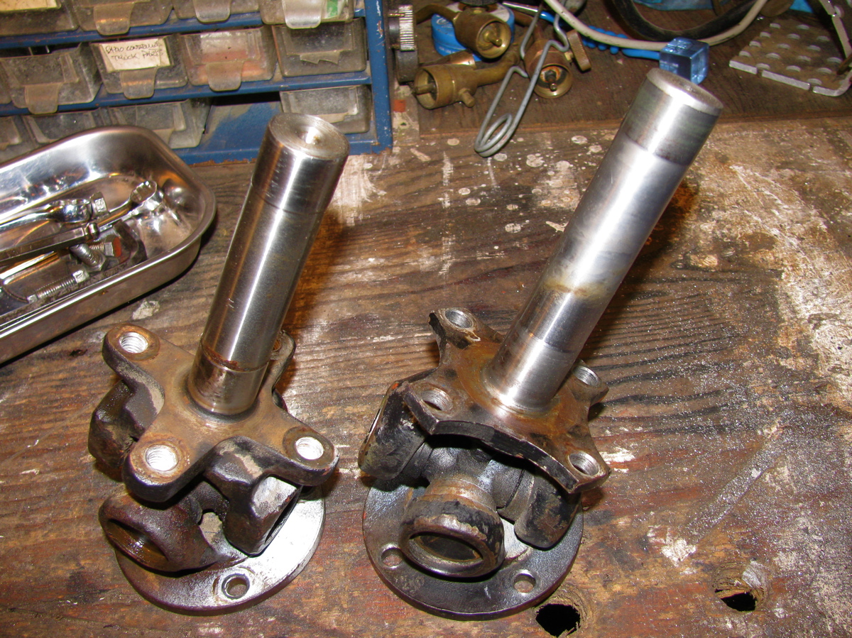
 See the dowel pin below the bolt holes in above pic? Wet area on trailing arm is due to some rust busting liquid I squirted on exposed threads on the 4 bolts holding the bearing housing on to the trailing arm. With the parking brake line detached from trailing arm it is possible to to pull off brake assembly from stub axle and lay to the side on the ground.
  Now remove the 4 bolts (17 mm?) that holds the bearing housing onto the trailing arm, and then the housing should pull right off the stub axle.
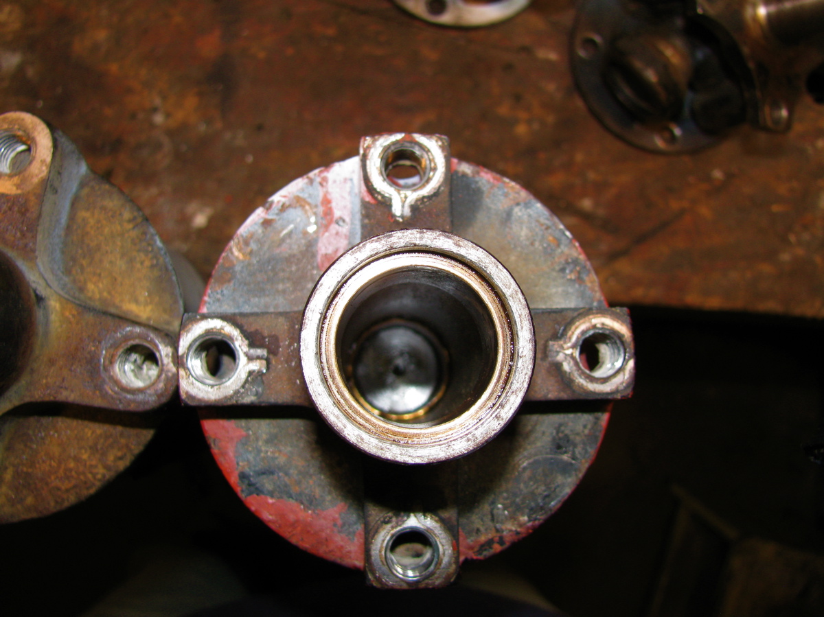
  Pretty ugly in there eh? Caked on dirt and some rust. I took the bearing housing to the bench for disassembly.
 The grease seals were stuck in tight, I had to put the housing in the vice and use a longish pry bar to pop them out.
  Above pic shows outboard grease seal removed and the inner race of the outboard bearing removed (it just falls out). On the inboard side, after the grease seal is removed there is a circlip to take care of.
  After circlip is removed the inner bearing can be removed by driving it out with a brass drift from the outboard side. The spaced sleeve in there between the bearings can be shoved to the side so that you can get the drift onto the bearing race. It took a bit of “drifting” to get the bearing out. If you have a press then you know how to do it better. Once that inboard bearing is out, the spacer is removed and then the outboard bearing outer race can be driven out. In my case that bearing was really stuck in tight. I used an old disk brake caliper piston to drive the bearing out, was a lucky good fit.

 There is a spacer in that gob of grease.
  Cleaned up the housing a bit, especially the bearing seats.
 All the parts arranged.
  Inboard bearing greased and carefully tapped in using that plastic headed dead blow mallet. Picture shows bearing started in housing, not fully seated.
  Bearings were tapped in carefully (a press would be better), the circlip inserted in the inboard side, the spacer installed and the grease applied liberally around the spacer, and the grease seals carefully installed. Again, picture shows bearing started, not fully seated.
  Now at this point, with the housing reassembled, if I had taken the stub axle off the van it would be pressed (or carefully tapped) into the bearings. But what I did was take the housing out to the van, slip it onto the stub axle making sure I didn’t damage the grease seals and that the spacer lined up on the shaft, and I pushed the housing onto the stub as far as I could. I bolted the housing to the trailing arm, then I used the brake drum and the big nut to slowly draw the stub axle into place. This method worked well. Oh, before I put the housing back onto the trailing arm I cleaned out the dirt and loose rust from inside the arm and shot a whack of Fluid Film in there.
  Then its a matter of putting the brake assembly back on, re-attaching the brake line (was a pain, I had to loosen the slave cylinder on the backing plate to get the thread started on the union), then the brake drum, big nut snugged up but not torqued, the wheel, and then get the van off the jack stands. Torque the big nut to spec (see diagram at beginning of post for torque specs), split pin installed, lug nuts torqued, and its done. No play in bearing when the wheel was grabbed, and the whine when driving was gone. I’m guessing that most Vanagon owners will only have to do this job once, or maybe twice, in the van’s life.
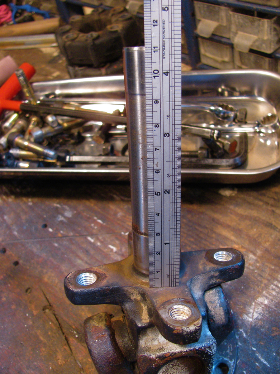
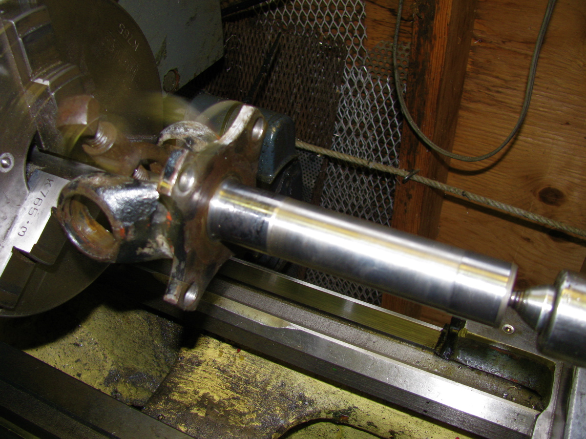
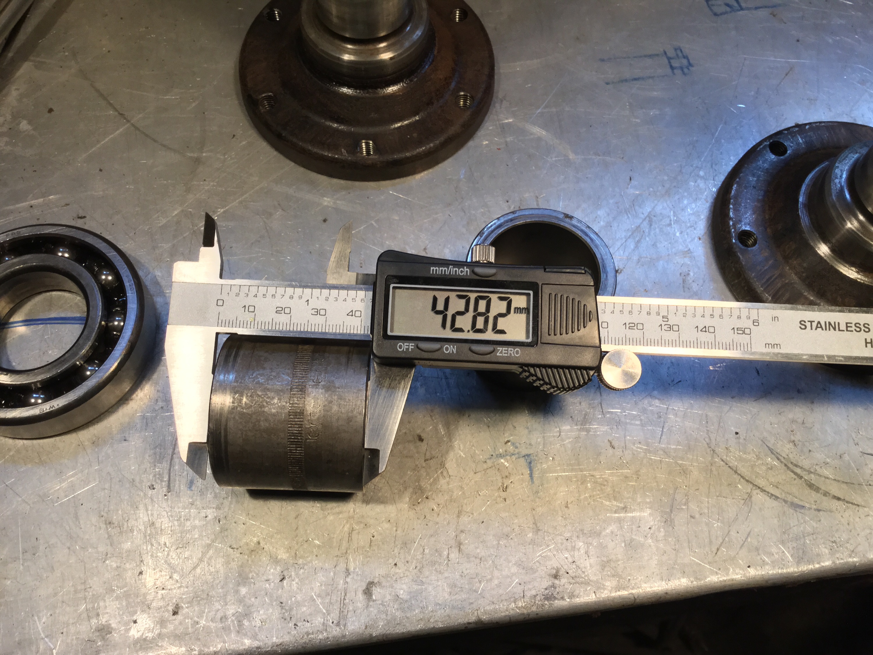
Addendum, April 30 2015, some measurements for Josh 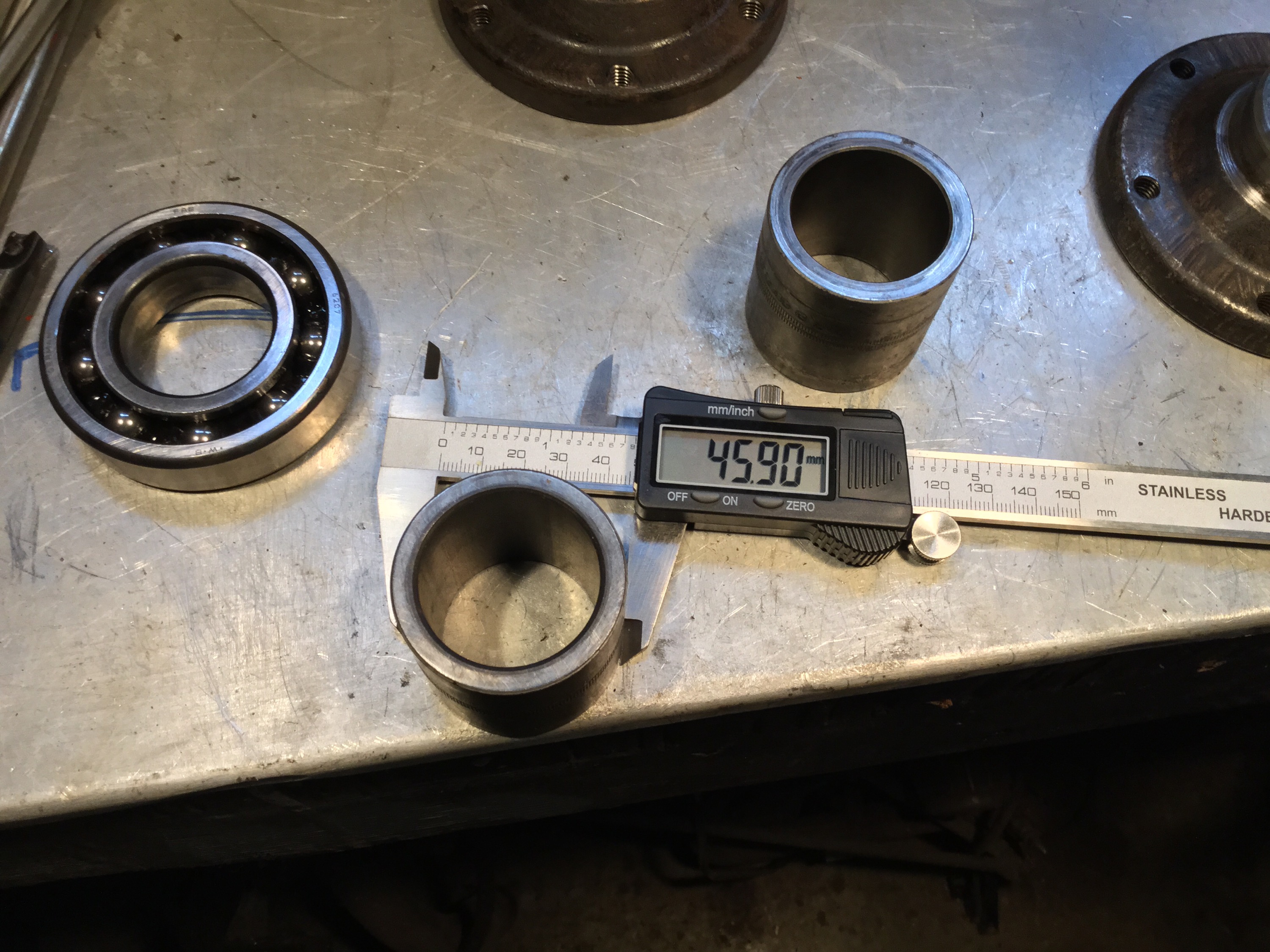


ATA – Bristol Hercules slide valve engine
Posted by albell in aircraft, around the airport on April 9, 2011
Correction: it is a sleeve valve, not slide valve engine. Of course… dunderhead mistake.
Three shots of this fascinating engine housed in the BC Aviation museum. More info can be found at this Wikipedia entry.


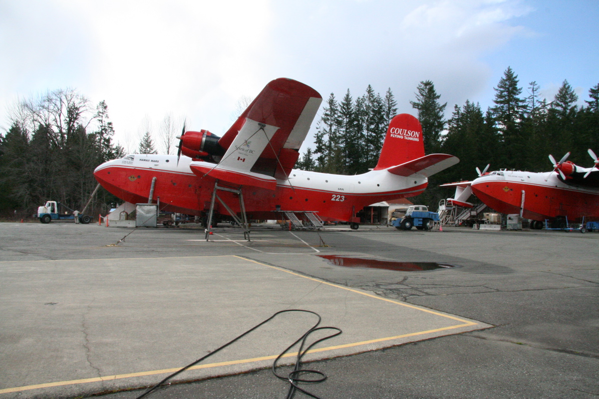
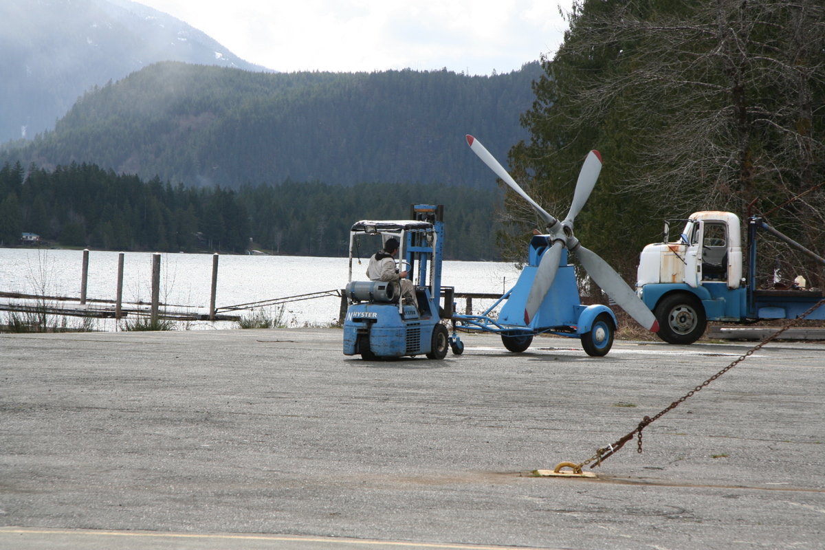
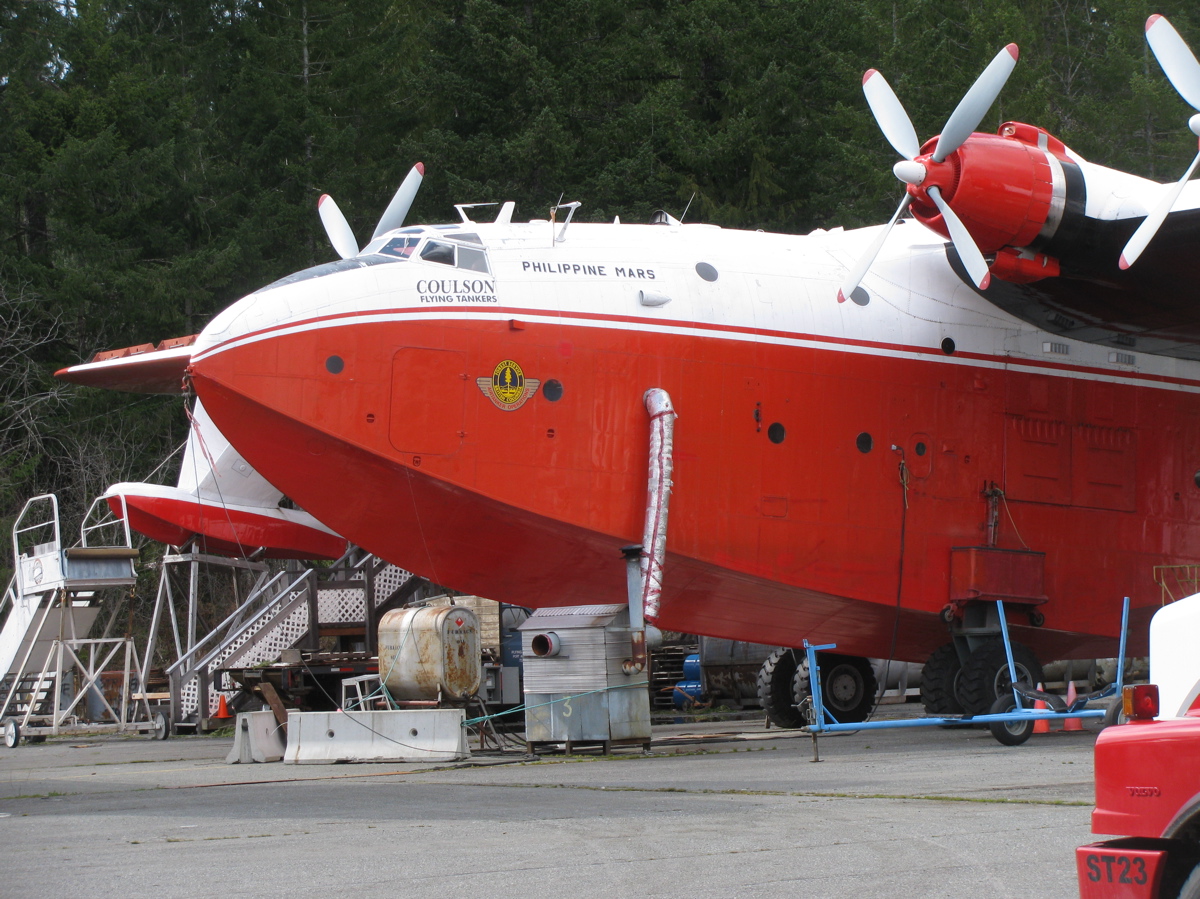
ATA – Martin Mars water bombers
Posted by albell in aircraft, around the airport on April 8, 2011
Not at my local airport, but at Sproat Lake near Port Alberni. One of the planes was having a prop removed.


Another logging road trip
This time with visiting Vanagon mailing list pundit David B. We headed to Port Renfrew, then north on that paved road to Lake Cowichan. From there it was logging roads to Nitinat and finally Sarita, a dry sort and booming ground on the south shore of Barkley Sound. Next day we headed west to look at the Pacific at Pachena bay, then north east to Port Alberni and got to see some nice machines behind the scenes at The Alberni District Museum and Historical Society , the Maclean Sawmill museum, and a quick peek at 2 Martin Mars water bombers at Sproat Lake. Then back to Victoria on civilized roads, stopping to look at the big Douglas Firs at Cathedral Grove.
The pics are a mix of mine and David’s.
Quick and dirty Westy table fix
Posted by albell in syncro, vanagon, vanagon mods on March 30, 2011
The old westy table I have in my syncro was loose where the metal base attaches to the tabletop. It used a form of captured nuts in the table top to secure it to the base, and those nuts were loose in the wood, and the holes were chipped and enlarged. I had used some glue to help hold things togther but that was a short lived solution. I think the newer Westy tables have a better system of attachment.
So I set about doing a quick fix. I had some scrap 3/4″ thick PVC sheet:

What was I thinking years ago when I painted that base yellow? I need to repaint it. I cut the PVC to size:

And countersunk some 1/4″ bolts:

Then some PL Premium polyurethane construction adhesive ( the poor man’s Sikaflex) to glue PVC to table:

Now I really do have to get rid of the yellow.
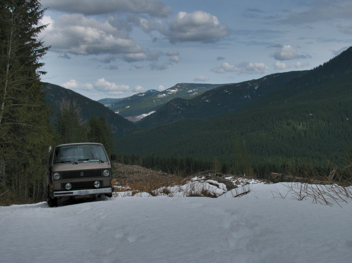
Gordon River trip
Last week my son and I headed out to explore a bit of the Gordon River watershed. The river starts close to Cowichan lake but flows southwest to Port Renfrew and the Pacific. We headed out from home to Port Renfrew then made our way “upstream”. This is the first bridge across the river, near Port Renfrew. Yes, the water was clear and this colour.


We headed on, exploring various logging spurs to see if we could find a camping spot that had a view, and had some snow. The problem we encountered was that when we found snow on those spurs, it was heavy corn snow, got deepish quickly (20 – 30 cm) and with the steep grades we really couldn’t make much headway.

We ended up at a spot in a recently logged area, about 50 meters below where the snow started.


Well, we had a bit of a view and no shortage of table material.

A word about logging in this valley. I’m guessing most of the watershed, was logged by the middle of the last century. It would have been mostly Douglas Fir and Western Red Cedar, big trees. Now what you see is second growth, Doug Fir, Hemlock, some small cedars. The biggest stumps I saw were about 60 cm diameter. That section in above picture had around 50-60 growth rings. Here are some pic of the recently logged area, showing some old grey stumps from the first cut.


Next day we headed on, again being foiled by steep snow covered spurs, and we decided to try to get to the trail head for Mount Sutton. We found the access road on the north side of the river to be choked with alders. This road starts at the site of the old Gordon River logging camp, which at its peak (1950?) was one of the biggest camps on the island (google map ref). Pretty well nothing remains of the camp now, but if you dig around this site you can find some info and pictures of how it used to be. One strange relic remains, a Mk III Cortina under a fairly large section of cedar log.


You have to be alert for logging trucks, there was about one every 10 minutes.

We headed back west, “downstream” and explored the road that, on the map, leads to the Gordon River Caves. It was another steep and snow covered spur, but we did manage to find a small waterfall and have lunch.


Further west we drove up the north side of the valley, again through logged areas, up steep (measure 29 degrees on one section) spurs, and again foiled by heavy snow. Saw elk tracks though.

We backed down a few meters and found a room with a view.

And some old wolf scat.

It started to rain that night, and the next day. We drove east, “upstream” and came out to civilization near Honeymoon Bay at Cowichan lake. One benefit of traveling on active logging roads is that they are graded often.

It was a fun trip with a few more dents added to the syncro.
Cooper 500
JAP 500cc motor, Formula 3, one of the first Cooper race cars. I notice the U-joints on driveshafts are not oriented 90 degrees apart.


The JAP engine cutaway.

ATA – Grumman Mallard and T-28
Posted by albell in aircraft, around the airport on March 22, 2011
This T-28 is usually in hanger adjacent to the one I previously posted. The painted black stripe on the fuselage only partially masks the exhaust stains. The Goose Mallard is one of 2 Grummans at the airport, but now after screwing up id’ing the Mallard who the hell will believe me that I am sure the other one is a Goose :).


J. Clark and car
I don’t know what Formula car this is, but I find it interesting as it’s a good shot of the rear suspension and transmission. Notice the Giubo on the inboard end of the driveshafts.

This diagram of the rear suspension of the Lotus 33 F1 car (and I’m not saying its the same as above car), doesn’t really shed more light on the inboard joint, but it is interesting.

Van Dorn drill
Posted by albell in metal working, metalworking on March 18, 2011
Still works and able to break your wrist or whip you off the stepladder 🙂 Single speed, brass trigger with very positive on/off action.

Greenlee punches
Posted by albell in metal working on March 18, 2011
An old set with a nice leather case.


ATA – Sikorsky S-61
Posted by albell in aircraft, around the airport on March 9, 2011
Cougar Helicopter’s (part of the VIH group) S-61.

Dodge Powerwagon and Johanson Lake
Omineca district, Northern B.C., 1978. Late 40’s (?) Dodge Powerwagon.

Here is an ad for the 1946 Powerwagon:

Johanson Lake

Google map ref for Johanson Lake
Milking a Jersey
Boy, the milk is good, and lots of cream. Next time the stainless bucket will have a cleaner outside.


After 16 hours, pretty well all the cream has risen. Jersey’s are known to produce this nice cream-coloured cream, and a fair whack of it. Wikipedia says 6 % butterfat (compare with Holsteins at 2.5 – 3.6 %).

Icebergs at Campbell River
Phil Z. took these shots a few days ago. Global warming, feh 🙂


Vanagon ignition switch
Posted by albell in syncro specific repairs, vanagon, vanagon mods on February 24, 2011
It has been “discovered” that the Vanagon ignition switch is a weak design. Why? Well it switches a fair bit of current and the contacts seem just adequate for the job. All right, I admit I have no real data to present to prove this, but maybe it is wise to have OCD and switch off accessories (heater fan, wipers, lights) before starting the van. If these loads are present then contacts in the switch have to handle a bigger current, and the resulting sparking will degrade the contacts over time. Mind you, the actual switch is relatively cheap ($20 – $40), so this really does fall under the category of Vanagon nerdom.
Excerpt from manual showing switch:

David B.’s photograph of dissected used switch:

I must be so bored to resort to posting such a flimsy entry 🙂
Update: Maybe its not such a flimsy entry after all, Jay Brown sells a relay package to reduce switch load.
Also, headlight relays on there own will reduce load on the ign. switch.
ATA – close ups of the Catalina
Posted by albell in aircraft, around the airport on February 24, 2011
Got lucky today and had the chance to get some quick up close snaps of the PBY 5. I even peeked inside… a lot of unpadded corners in there. Why that struck me I don’t know, maybe I am a closet Health & Safety officer. Anyway, word is that it will be flying again in the spring.


You have to watch this, Rick Mercer visiting Buffalo Airways HQ in Yellowknife, and in the winter.
Syncro and Ohio winter
Brett H. sent me this picture of his syncro. Its a good looking van, must ask him about the aux light mounts.
ATA – its all about the sky
Posted by albell in aircraft, around the airport on February 21, 2011
Usual spot, nothing much of interest except the busy sky.

Vanagon – N. American vs European tail lights
Posted by albell in vanagon, vanagon mods on February 20, 2011
Pulling together some stuff I have on the differences in the tail light assemblies. As some of you know, European tail lights have the provision for a rear fog light (Nebelschlussleuchte), that is, a brighter red tail light to be used during poor visibility. The light is controlled b a 3 position switch (off, front fogs, front fogs + rear fog) on the dash. I have one of those switches controlling my aux. lights. Part number for this one is 171 941 535A, the VAG says 251 941 535 is the one for the Vanagon – bet ya they are one and the same. Here are a couple of pics:


And here is a German manual diagram:

And here is an annotated English language diagram

And here is my diagram of the circuit boards (right hand side):

And now some pictures of a pair of right hand side tail light boards, “USA” vs “Europa”:

“USA” lens front:

“Europa” lens front:

“USA” lens back:

“Europa” lens back:

Arcane and nerdy stuff, eh Ben?
Campbell River February 18
Phil Z. sent me this nice picture.
Vanagon hiding behind trees, waiting to pounce on unsuspecting Toyota…

