Warning: what follows is a very long-winded and tedious description of my further exploration of propshaft U-joint angles. Experienced and knowledgable readers, please, cut me some slack and refrain from face palming at my antics.
Being quite adept at re-inventing the wheel, I’m now re-inventing measuring propshaft angles. If you are a regular reader of this blog, and man it feels good to write that (evidence of my amusement with small things), you know I have spent some time exploring the flange angles of the transmission and front differential (my previous attempts, one, two, three.). I came cold to this subject, never having to deal with anything like this before, and Bentley has nothing to say about the matter. So perhaps I could be forgiven for my naive approach to the matter. Perhaps, but really no, I should have cut through the crap right away.
A little background
The transmission is connected to the front differential via a propshaft. On each end of the propshaft are U-joints (single cardan joints) that allow a little bit of misalignment between and movement of the transmission and the front differential. Now the problem with U-joints is that they do not transfer the rotational motion of the propshaft perfectly smoothly, ie. without pulsation, especially when the U-joint angles are greater than 3 or 4 degrees and also if the angles differ from each other more than 1 degree (more on those angles later). Most of you know this, and also about the correct phasing of the the U-joints on each end of the shaft, but I do recommend having a look at this document from Spicer that explains all:
Spicer info on driveshaft install, angles, vibrations, etc. (pdf).
And this Spicer document on measuring angles succinctly describes using Spicer’s angle finder doodad.
Spicer info on measuring angles
One subject not really covered well in that document is compound angles. That is when there is mis-alignment is in 2 planes, ie horizontal and vertical. I’ll go into that at the end of this post.
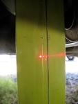
Over time I became dissatisfied with my last attempt at measuring flange angles with my laser tool. Don’t get me wrong, I think it is a pretty neat way of measuring the flange angles and it measures both in vertical and horizontal planes. But you need to have the propshaft removed.
After some email exchanges with J. Slider, I reconsidered the protractor/angle finder method of measuring flange angles. I wasn’t very happy with the results I got when I tried this method a while back. I was unable to get consistent results measuring the flange angles with my propshaft removed. It came down to getting the electronic angle finder positioned correctly on the transmission and front differential flanges. But Jon’s argument for the angle finder method convinced me to try again.
I was sidetracked by an idea of a false propshaft jig thing. I reasoned that if I could make a jig that mimicked the propshaft but was constructed so that flange angles could be more easily measured it would be a good thing. I even thought of making a false propshaft with fixed, *ideal* flange angles that I could use to adjust the transmission and front diff. mounts. I still think this would be a worthwhile tool to make for those folk who install propshafts in vanagons.
– This flurry of innovative thinking (ha!) coincided with me removing my propshaft and having it checked for balance by Royce at Island Torque Converter & Driveshaft. Royce is THE guy to take your propshaft to for repair/balancing. He does good work, prices are very reasonable, and he is willing to work with you in solving driveline issues. Local (Vancouver Island) phone # is 250 388 4248 –
Royce and I talked about the syncro propshaft and about making a shaft with Rzeppa type CV joints. That discussion is another story but when I was Googling around with the idea of Rzeppa joints on shaft I came across a document describing the install of a marine, Rzeppa jointed, short prop shaft. In that document (you can see it here) the use of jigs that I described above is detailed. Foiled again. Is it always to be thus? Are all my ideas “a day late and a dollar short”?
I took my propshaft to Royce around the 15th of December and got it back the next day. But with one thing and another I did not get the shaft re-installed in the van until the 9th of January. During that time, when I was not working, eating, drinking, Xmas shopping, sleeping, putting up then taking down Xmas trees, etc, etc, I was mulling over the propshaft jig idea.
Too much mulling, not enough action. So I ended up going back to the protractor/angle finder on the installed propshaft method. You’ve seen this before, and it is described in the Spicer document, I just added a very minor twist.
Home-made tool
I mentioned at the beginning how I was never happy with the measuring propshaft angles with the angle finder because I could not get a good surface to place the gauge on. So I decided to do what others have done and use the ends of the U-joint bearing cup as the reference surface. That meant making a little tool.
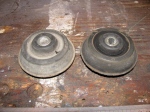
A bit of scrap steel from some failed project.

Turned it down and machined a recess in one end to accept a rare earth magnet.
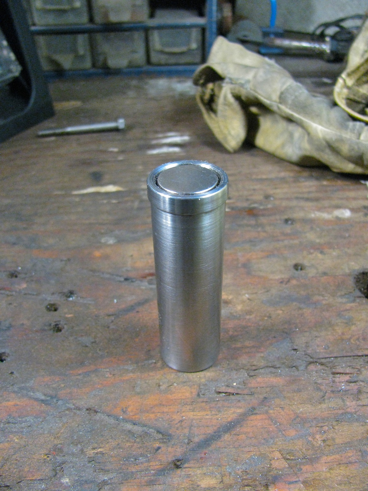
Fits in fine, held in firmly by magnetism and Locktite.
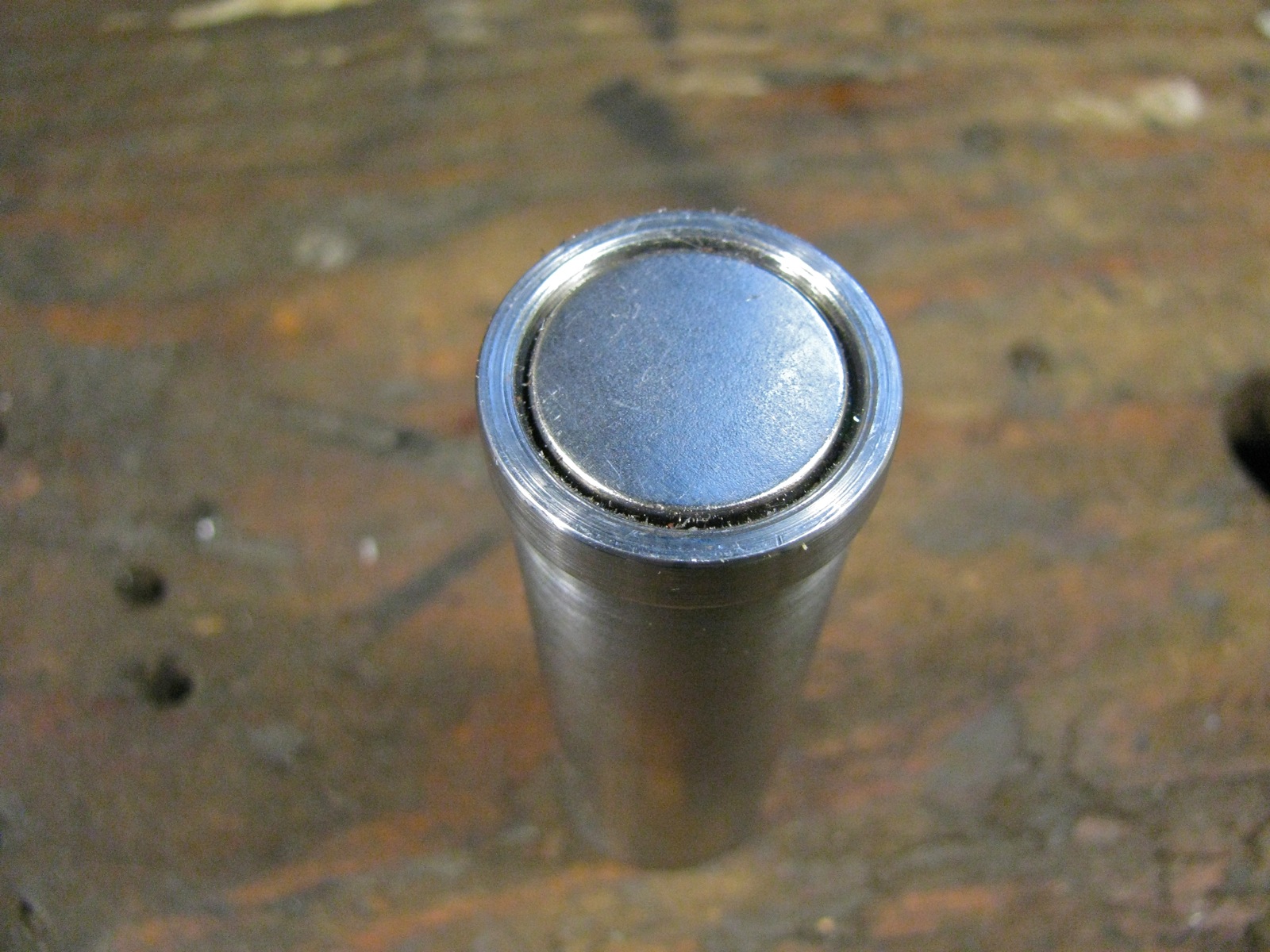
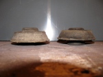
The magnet face is recessed from the rim of the tool by a gnat’s crotchet.

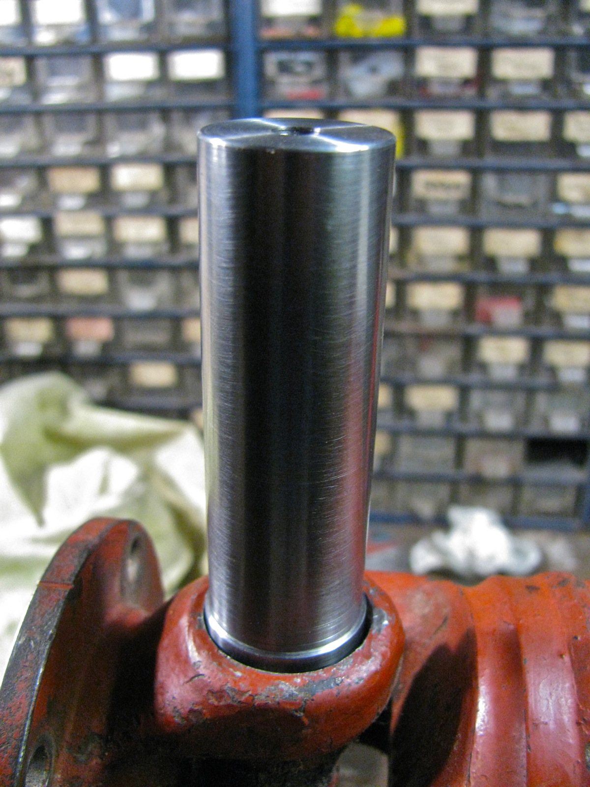
Here is my other propshaft, to be used for trial fitting. Big note here, ideally the circlip should be removed so that the tool can lie directly on bearing cup. But I reasoned that these circlips would be lying parallel to the bearing cups. Any dirt or damage to the circlips would screw things up.

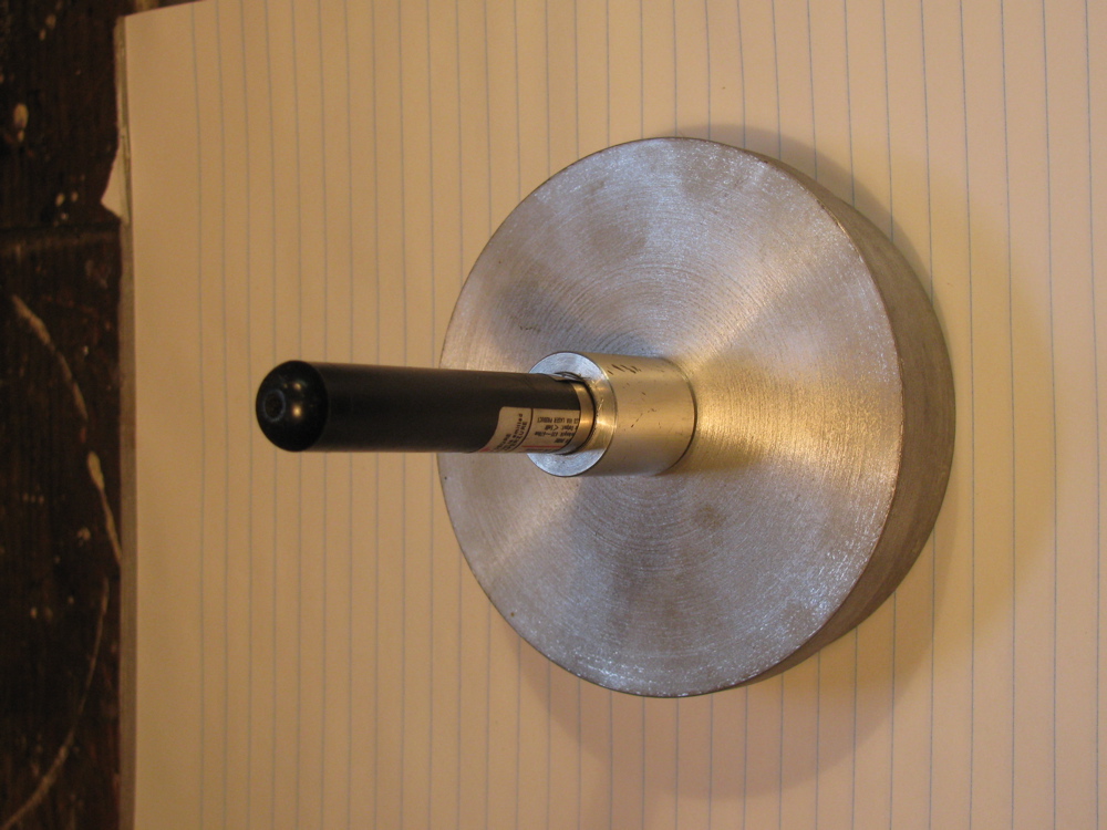
Tool on the joint.
Angle finder on tool, held by magnets on side of angle finder. It looks like the angle finder is resting on flange, but it is not.

Angle finder on end of tool. I was not sure at this time which way would be better.
A bit of channel to provide a base to measure the propshaft angle.

Trying out the tool
Ok then, out to the van. First I had to install the re-balanced shaft (not the red one pictured above). I jacked up one side of van and supported on blocks. Wheels off the ground.

Small aside, I finally replaced the 1/2″ bolt used to hold the jack adapter onto the jack with a gated pin thing.

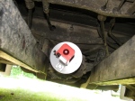
After the propshaft was installed (please note, I do insist on loosening the 3 bolts that go through the rubber mounts on the front diff. when I am installing/removing the shaft) I took the van off the blocks, released the parking brake and chocks, then crawled under to have a go at measuring angles. First I moved the van back and forth so that a bearing cup on the U-joint yoke that is attached to the flange was pointing directly down. I gave it a bit of a scrub then attached the tool.

See how the angle finder is a little askew on the shaft of the tool? This affects the angle measurement. It was hard to get the angle finder aligned true to the shaft when I was scrooched up under the van. Would have been much easier if the van was on a lift. But I persisted, went on to measure the propshaft angle.

And see how I do not have the angle finder aligned along the channel? It is askew too, and this affect the readinghh. And then on to the front diff. end of shaft.
Repeated the procedure a few times.

A bit better alignment on channel.

Again on the front.

And on the rear.
But I was not happy with the procedure, I was not sure of confident of the accuracy of the readings.
V-block modification and engine carrier adjustment
I tried a nice little Starrett V-block on the tool. I thought it might help me to keep the angle finder aligned along the long axis of the tool.

I was running out of afternoon and I wanted to try something more. I knew from previous measuring that the transmission flange pointed down more than the front diff flange. I wanted to reduce that angle, but I also new that there really is no easy way to do that. The transmission mounts towards the front of the transmission are really awkward to get at and fiddle with (especially when you don’t have a lift), so that leaves the engine mounts at the rear. But the arrangement/relative placements of the mounts means that it takes a fair bit of movement at the engine mount to effect a little movement at the transmission flange. Perhaps these data from R. Jones illustrates this (front diff. data included).
“4) I measured the distance between the flanges and the
mounting points, tranny and front diff, and worked the ratios.
Using washers, here’s what one can do:
a) raise front mount, front diff, lower flange.
1 unit raising gets 0.83 units lowering the flange.
b) raise rear mounts, front diff, raise flange.
1 unit raising gets 1.2 units at the flange.
This is the wrong way however.
c) lower tranny at front mounts, lowering flange.
1 unit at mount gets 1.25 units at flange.
Again, this is the wrong direction.
d) lower engine at carrier attachment to frame,
raise flange. 1 unit at engine gets 0.25 units
at flange. Hardly worth it.”
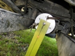
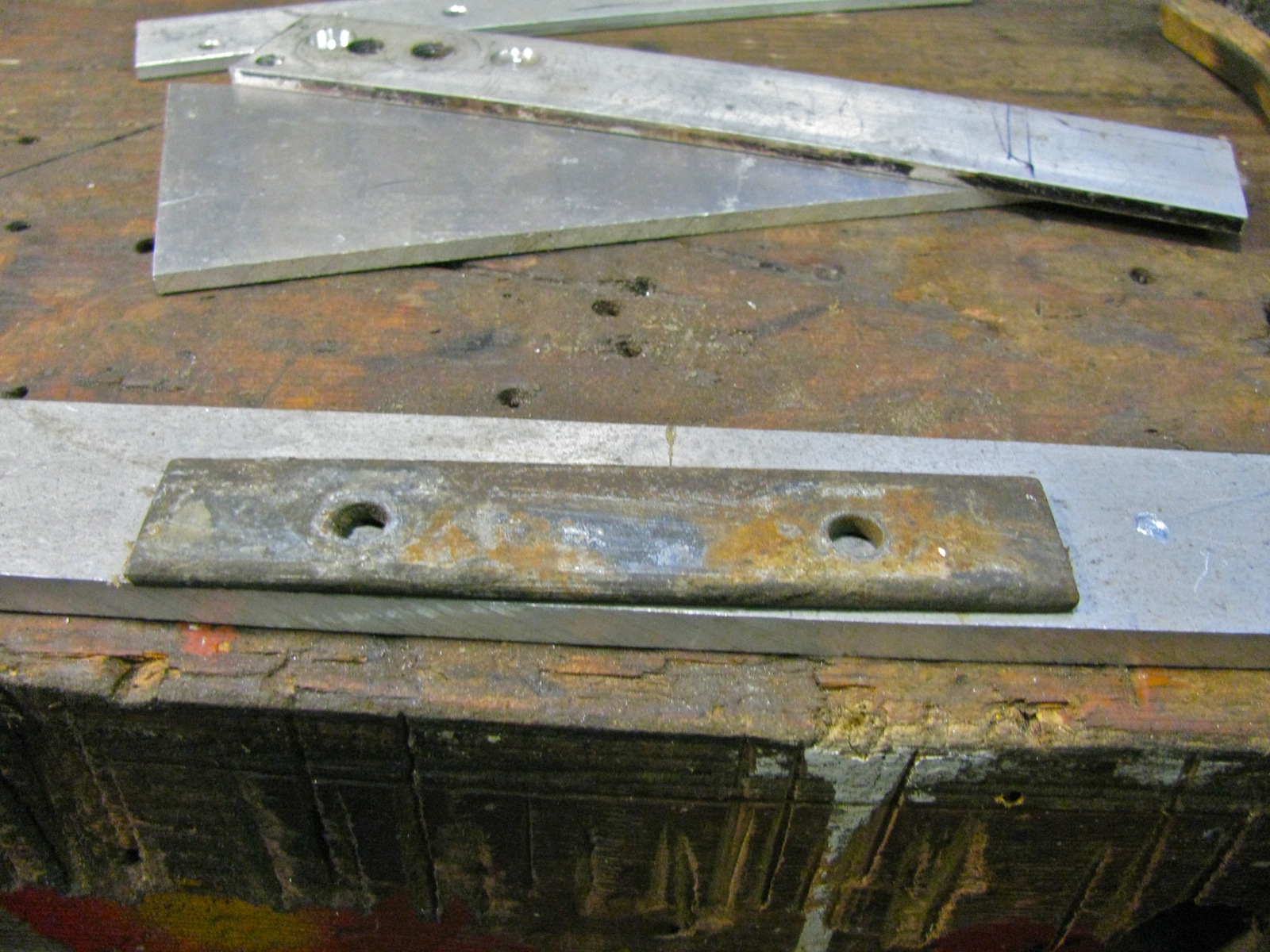
I wanted to try “d”. So I supported the engine carrier (“moustache bar”) with a jack and removed the 2 bolts, each side, that hold the bar to the van frame. I had no time to record flange angles vs. amount of lowering of rear carrier, and I decided to try 5/16″ as the distance lowered. Handy number, I had some 5/16″ aluminum plate scrap on hand. On the top side of the flange on the van body that the carrier mounts to there is a steel backing plate. I used that plate to lay out the bolts holes in the aluminum spacer.
Holes drilled.
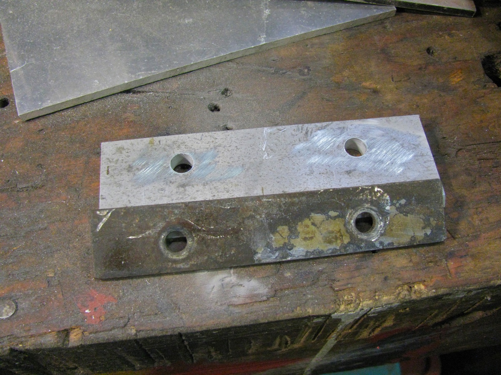
And spacer inserted. I used longer bolts. Damn mudflap mounting strut interfered.
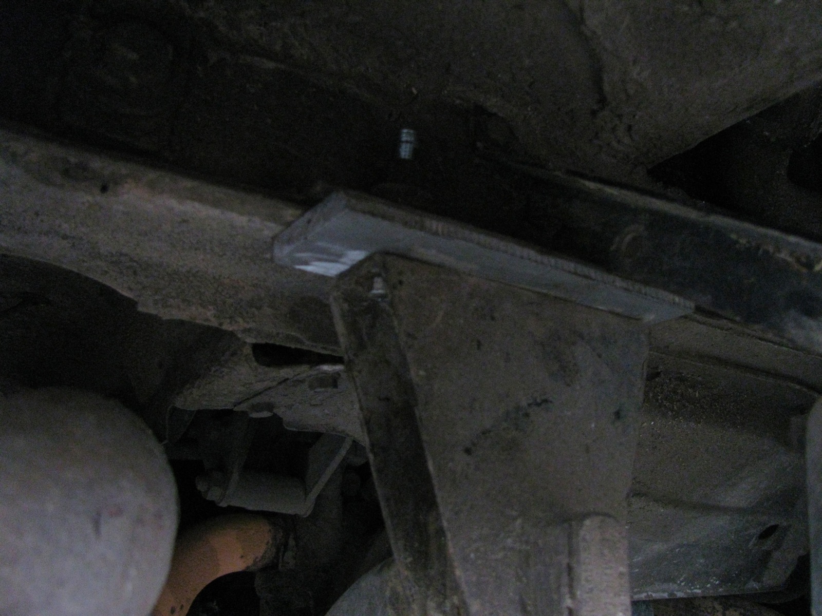
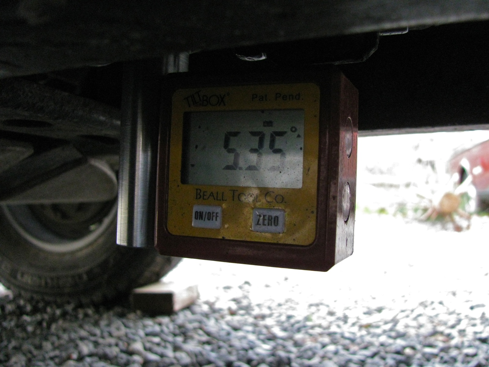
Maybe you can tell, the light was fading fast. I got back under and measured angles, using the V-block innovation.
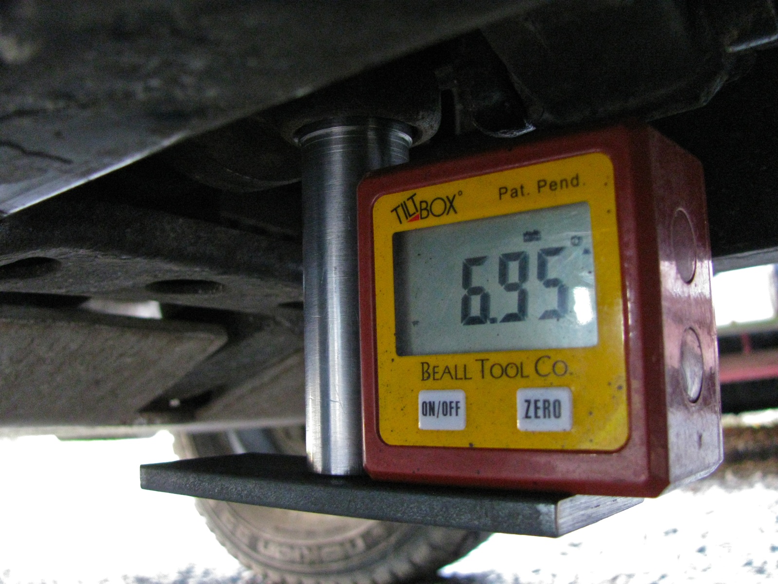
Transmission flange angle.
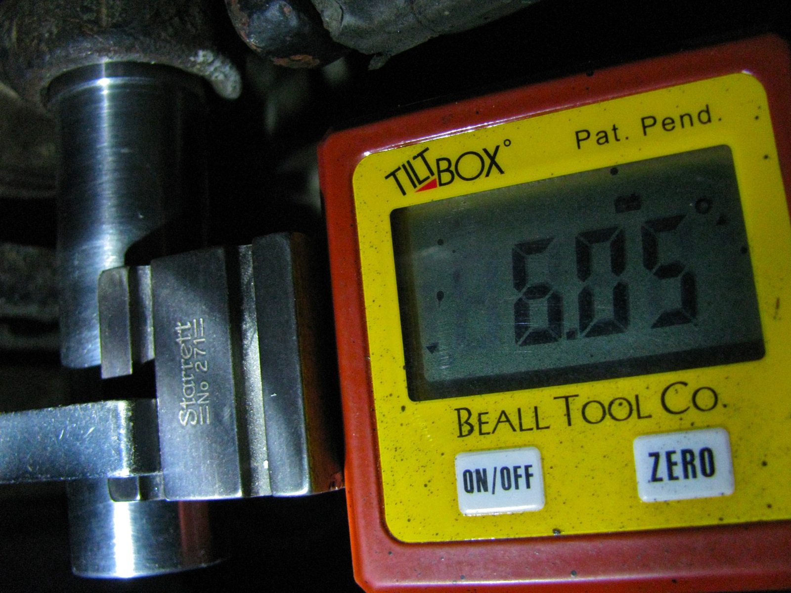
Front diff. flange angle.

By now it was dark and I was cold. I left things as they as far as I got to: rear engine mount dropped by 5/16″.
It now occurs to me that I have not mentioned another little thing I did (a year ago) to resolve flange angle difference – I removed the topmost metal washers of the two rearmost mounts of the front diff. This did drop the flange of the front diff. a bit – I reasoned back then, that if I could not reduce the flange angle of the transmission the I would increase the flange angle of the front diff. I hoped that matching the flange angles did more to reduce vibrations than trying to get both flange angles below 4 degrees. I’ll clear this up at the end, I know this story is getting very muddy right now.
Road test
Okee dokee, I drove the van for the next couple of days. Felt pretty smooth, my 50-60 kph minor vibe has gone. I do have the very, very slightest vibration especially when accelerating, at around 40-45 kph. But I noticed this when the propshaft was removed so I am discounting that it has anything to do with the shaft.
I was pretty happy with this. I’d say that the re-balanced shaft is sweet.
Further modification to the tool
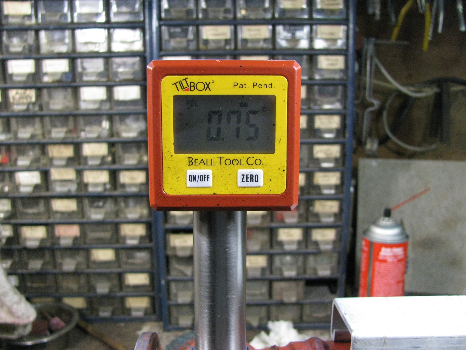
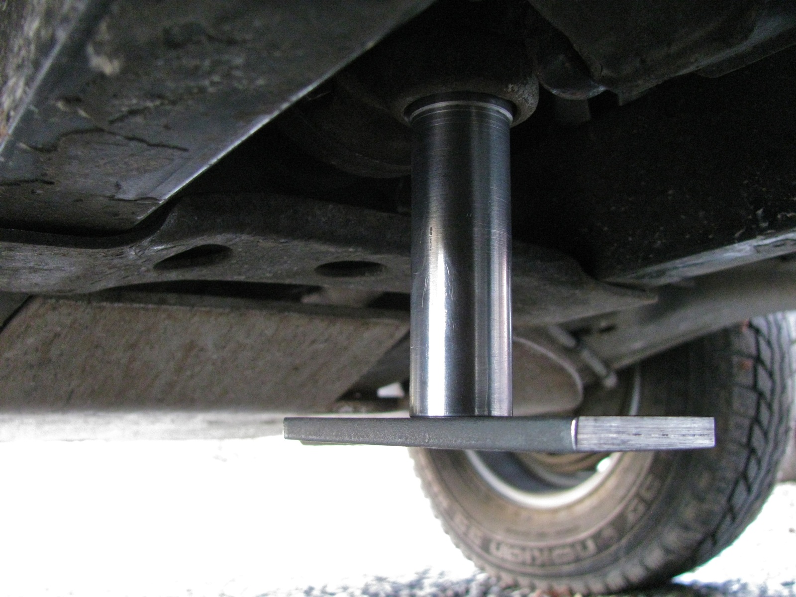
But I still wanted to measure the flange angles with somewhat more confidence. I cut a chunk of 1.5″ X 0.25″ hot rolled flat stock, drilled a hole, and screwed it (1/4 “- 20) to the end of the little tool. I checked it for square, was good. Now I had a better reference surface to place the angle finder against, and I could line up the long axis of the plate with the propshaft.

Here it is on the transmission end of the shaft. It is much easier now to use the angle finder to determine that the tool is pointing straight down, and the plate can be lined up fore and aft with the propshaft. Those two things are important in measuring the true angle of the flange. Remember, the tool is on the bearing cup in the flange yoke of the U-joint. That means it projects the angle that the transmission flange is making with respect to the propshaft.
One way of doing it. The angle finder was inline with the bottom plate of the tool. This was not a recorded measurement, I had not adjusted propshaft so that tool is pointing straight down.

I found that having the angle finder in this position was the best. The magnets in the angle finder held it to the vertical shaft, but still allowed it to be aligned to the bottom plate.
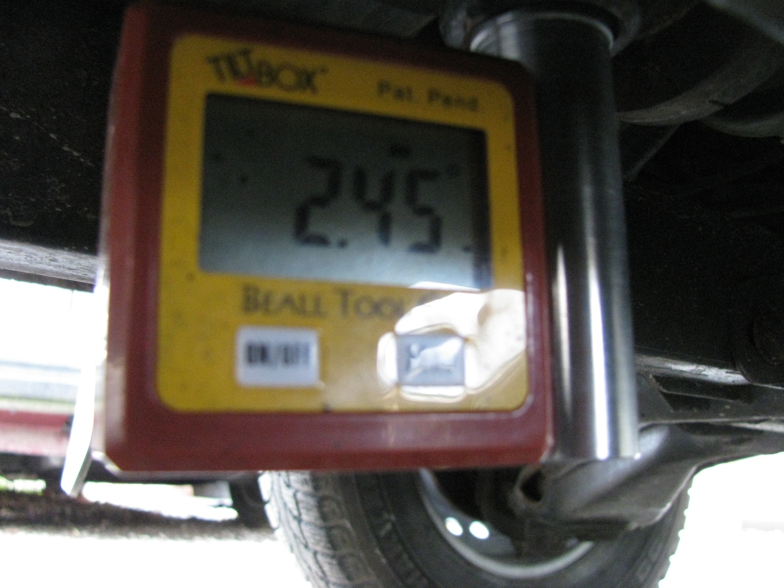
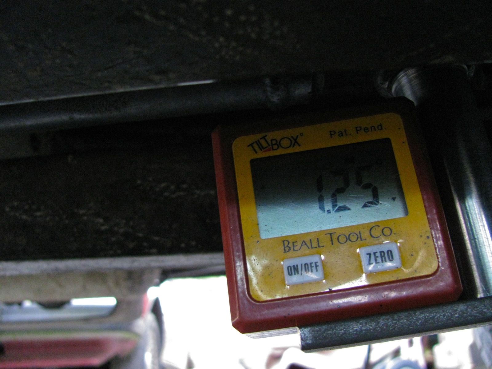
A another measurement (using the channel) of the propshaft angle.

And a good measurement of the front diff flange angle.
Results
Ok, I was getting more consistent measurements, now to look at some of the data. Remember, we are measuring relative angles here, not absolute angles. For example, the propshaft could be pointing down towards the front at 1.30 degrees, or at 2.85 degrees depending (apart from measuring errors) on the level of the van (ie just exactly where it was parked in my driveway). The sketch below summarizes my results. The top cartoon represents the situation right after I installed the propshaft. Let’s go over it, bit by bit.
The transmission flange (and the transmission and engine) is pointing down towards the front of the van at 5.5o degrees. The propshaft is also pointing down in the same direction, but only at 1.30 degrees. If we subtract the propshaft angle from the transmission flange angle we will find that U-joint operating angle, and it is 4.20 degrees. Remember: if the angles are in the same direction then subtract the smaller angle from the larger angle to find the joint operating angle.
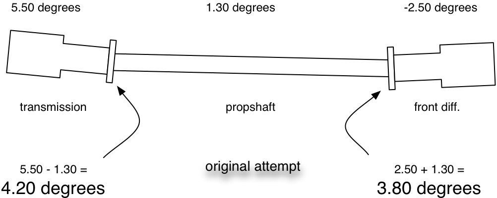
At the other end the front diff. is pointing down towards the rear of the vehicle, in the opposite direction of the propshaft angle. I added a negative sign to that measurement to remind me of its different direction. So in this situation the absolute value of the front diff. measured angle, -2.50 degrees, is added to the propshaft angle of 1.30 degrees. Result is a 3.80 degree joint operating angle. Remember: if the angles are in opposite directions then add the absolute values of the two angles to find the joint operating angle.
As clumsy as those two paragraphs are, I hope you get the idea of how the operating angles are arrived at. Of course with an electronic angle finder I could have zeroed on the propshaft angle and read the working angles directly. But I thought it would be clearer to me and to you if I did it explicitly.
Now the measurements after I installed the 5/16″ (8 mm) shim back at the engine carrier.

And finally, the same set up but this time more accurately measured (bottom plate added to my home-made tool).

I am fairly confident in this last measurement. Even if it is not perfect, I am sure the two flange angles are within 0.2 degrees of each other, though I do wish that the operating angles were less.
Compound angles
At the beginning of this post I said I was going to discuss compound angles, so here we go. The above sketches show angles in a vertical plane, but you can imagine that the same thing could be going on if you could look down from above. The transmission and front diff. could be laterally mis-aligned. What is interesting, is the combined effect of both lateral and vertical misalignment. The Aquadrive document I linked to previously has some good information on compound angles.
The accurate formula for calculating the compound angle is:

Lovely stuff eh? Shall we do an example? (and please God, let me do the math correctly).
Let’s say we have a vertical flange angle (ie the kind we have been measuring ) of 4.1 degrees. And let’s say the lateral angle is 1.0 degrees. First step is to find the tangents of those angles.
tan 4.1 = 0.0716808913
tan 1.0 = 0.0174550649
we square both of these numbers and add them together:
(0.0716808913)^2 + (0.0174550649)^2
= 0.0051381502 + 3.0467929066e-4
= 0.0054428295
then we take the square root of that number and we get:
0.0737755345
now we take the arctan (inverse tangent) of that number to find the answer, our compound angle:
compound angle = arctan (0.0737755345)
compound angle = 4.22 degrees
(Another example – 4 degree vertical angle and a 2 degree lateral angle, then the effective compound angle would be 4.47 degrees)
Not much of a difference, 4.22 degree compound angle compared to 4.10 degree vertical angle. So should we worry about lateral misalignment? Well, in the stock set up there is some room to laterally adjust both the transmission and the front diff. The old trick of leaving the front diff. mount bolts a little loose after installing the propshaft, then driving the van for a few miles before tightening those bolts, probably serves to reduce or eliminate lateral mis-alignment. But with vans that have non-stock engines/engine carriers installed, then there is a very good chance of having the engine and transmission laterally askew enough for that trick not to be enough.
Conclusions:
- no matter what you read or hear, in the vanagon syncro the propshaft operating angles should be 4 degrees or less (but not zero degrees). Ideally they should be less than 3 degrees. Unfortunately there is no easy way to adjust the front diff and transmission vertical flange angles to achieve this. On vans with engine conversions and modified engine carriers, careful attention MUST be paid to the transmission angle.
- U-joint operating angles should be the same or within 0.2 degrees of each other.
- measuring the angles can be done fairly accurately with home-made tools. A smart phone with an inclinometer app could be used instead of my little electronic angle finder. But some sort of adapter between the joint and the phone must be used to ensure accurate and consistent readings.
- lateral misalignment of the transmission and resulting compound angles are very important to check and deal with if a non-stock engine has been installed. Remember that the angles combine and result in an effective angle greater than any one of the individual angles.
- Your man on Vancouver Island for propshaft balancing is Royce at Island Torque Converter & Driveshaft. Phone # 250 388 4248