Archive for category syncro specific repairs
Sway bar drop link sleeve modification
Posted by albell in metalworking, syncro specific repairs on July 22, 2010
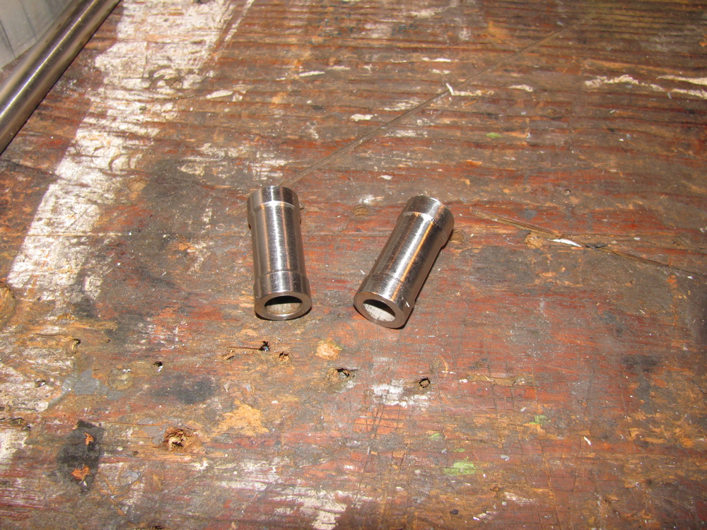
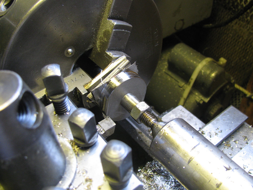
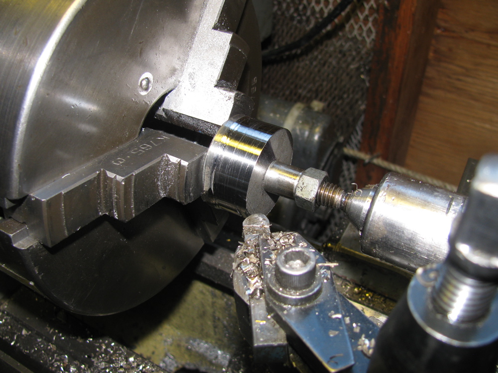
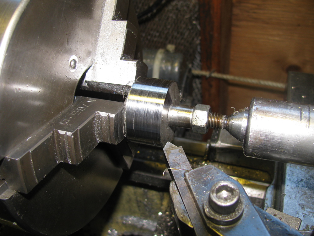
Fellow syncro owner Doug M. pointed out that I had made the drop link sleeves too tight a fit in the radius arm hole and that would limit the amount of movement needed in the rubber bushing-drop link connection. He is right that the joint there needs some degree of movement, limited and moderated by the rubber bushings. So to correct this I lathed down the centre sections of the sleeves, from 0.650″ to 0.600″. I had to make a quick and dirty mandrel to mount the short sleeves on the lathe. The length of the narrow section was judged by eye so consequently the 2 sleeves are slightly different.


Prop shaft vibes – maybe solved?
Posted by albell in syncro specific repairs on July 11, 2010
Last week I had some success in reducing prop shaft vibrations. If you read this blog you know I have been chasing this problem up one tree and down the other. One thing to finally clear up before I go on, is the question of the presence or not of a plastic spacer on the front mount of the front diff. I think I can conclude, for sure, that on my diff at least, there is no plastic spacer(s). The hole in the diff mounting ear is too small in diameter to allow the spacers found on the other mounts to fit.

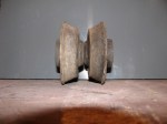
Here is a pic of one rubber mount (they are installed in pairs), a stock plastic spacer, and a home made spacer when I was still thinking my van was missing them.

As is, this still leaves the front diff flange pointing down at 3.7 degrees which is not close to the transmission flange angle of 4.6 degrees. By the book, these angles should be within 0.5 degrees. When I say by the book, I am not referring to the Bentley manual which has no information on this subject. Instead, I get this fact from a drive shaft makers publication, here;
I don’t like the fact that the transmission angles down that much, but I can’t really see how to raise front of trans. easily, and besides , it looks like there is little room above transmission to do this.
Out of frustration more than anything else, I decided to try adding weight to the drive shaft, thinking that perhaps the shaft was out of balance (I had replaced U joints, and who knows, it may have been out of balance before I got the van). I attached a gear clamp 3 ” from the front end of the shaft, right where there is a factory weight. test drive revealed no change. I rotated clamp 90 degrees and, by god, test drive showed a big reduction in vibrations, in fact the vibrations were almost gone.
Next step is to refine position and try additional weight. Local drive line repair shop does not have mandrels to do syncro shafts, but the tech. said he would be willing to make mandrels if supplied with measurements. I may be on to something.
Sway bar drop link refurb.
Posted by albell in metalworking, syncro specific repairs on July 11, 2010
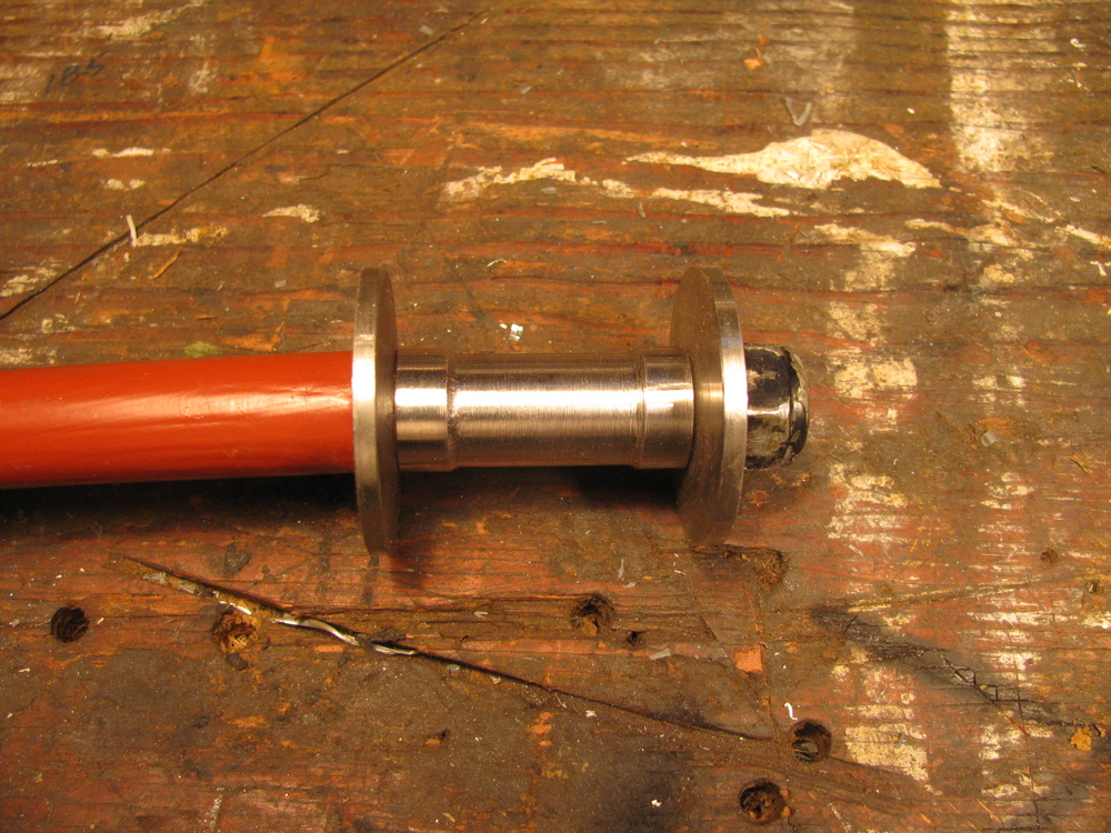
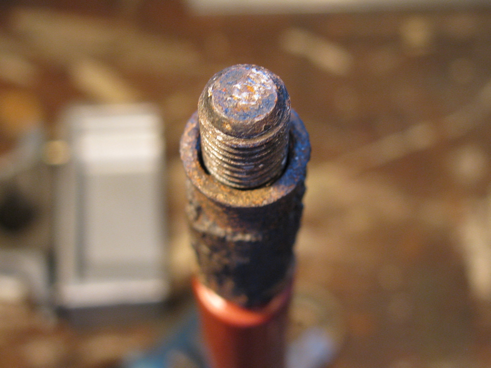
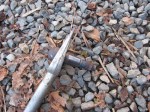
Between watching the Big Game and other things, I made some metal sleeves and convex washers for my sway bar drop links. The sway bar is off the van due to a broken link which I repaired earlier . A broken drop link seems to be a common thing, and its due in part to the steel sleeve inside the rubber bushings trapping water and rusting. This can cause the drop link itself to rust and also when the sleeve rusts out may allow the drop link to move more than it should, stressing it. I fixed the link by facing off the broken stub, then drilling into the link and tapping for a 10 X 1.5 mm bolt. The bolt was screwed in and tack welded. The bolt head was then removed and threaded portion cut to size. The picture shows the repaired link and beside an original. The stainless tubing was just an early try at finding a sleeve.

And just because I thought it a neat idea, I made bushings out of old skate board wheels.

I guess a diagram is needed showing all of the parts…

I needed to make new washers and sleeves (spacer tubes in diagram). The washers are dished and made of steel. The spacer tube is thick walled steel. I am not sure if the washers are still available, and I really wonder if the dishing is needed (allows more “wobble” in the drop link-rubber bushing connection).
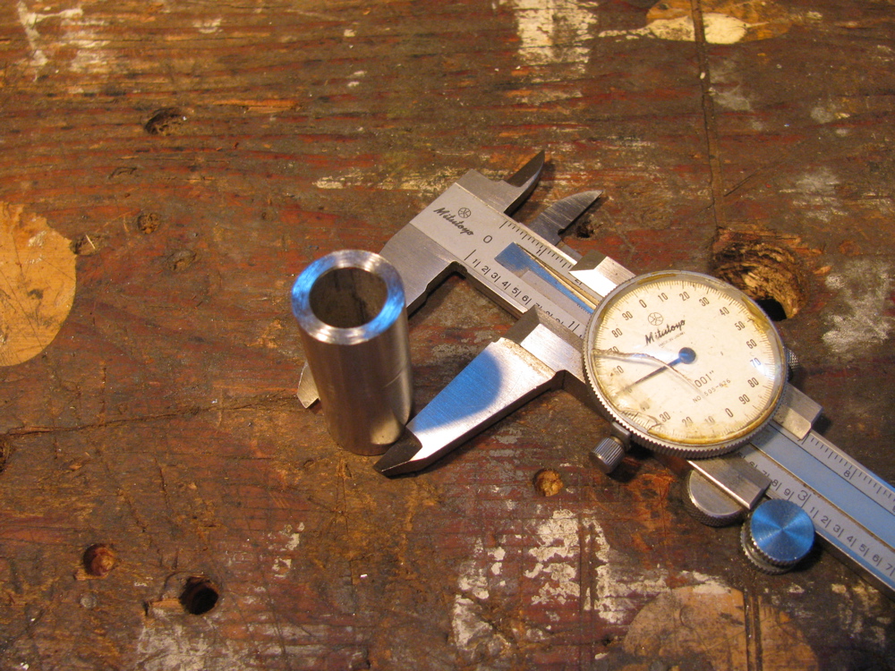
First the sleeves. Some schedule 80 stainless tubing was found at the local Metal Supermarket (I took drop link along for trial fit). I don’t know what the listed size of this stuff is, but a casual measure has it at 0.675″ OD and 0.42″ ID. The tubing was cut into 40 mm lengths (well, that’s what the rusty old stock sleeve was). I nipped out to test fitment in the hole in radius arm and found it was too large in diameter. I had to turn the sleeves down to 0.650″ diameter for an easy fit.
At this point I should mention that I am not a machinist, nor am I a talented amateur, so forgive any bad technique shown and the quality of the finished work. Now onto the washers. I had some stainless bar in the workshop, 1.5″ wide (not quite as wide as the stock washer diameter, you’ll see evidence of that in the pics), 0.187″ thick and I cut it up into rough bits, drilled holes in them and mounted them all on a really dodgy mandrel/spud/spigot/whatever on the lathe. Not the best technique, had to go slow and light to avoid hammering. Of course it would have been better if I had made them into hexagons at least before turning. Anyhow, I made the stack round. Then I mounted them individually on the mandrel and gave them a slight crown. Took a while but I still have my eyesight and digits.
The sturdy new washers are thicker than the old washers and this may be a problem when it comes to installing with the rubber mounts. If needed, I’ll shorten the sleeves by a couple of millimetres or so. Oh a couple of points… I was working on the “other side” with the lathe in reverse when making the washers convex. And you can see evidence in the finished washers that my stock was not quite wide enough, not big deal, just aesthetically crap.
Oh, one more thing, I ground off the little collar seen around hole in washer after I took the pics. The collar was left over from the lathe work. When the washers and sleeve are assembled on the drop link, and the nut is tightened, it all feels pretty solid and strong. I still would like the sleeve to be a snugger fit on the drop link, but probably is just fine as is.
I need to find some rubber bushings now. You can buy stock ones, but criminy, they cost $10 a pop!
Edit: see here for sleeve modification


PS. For images and prices of the “real” parts, check this page from Van Cafe
Syncro Westy – rust treatment and Zetec engine
Posted by albell in syncro, syncro specific repairs on June 29, 2010
Whereas I just poke around the fringes of syncro repair, Ed In Vancouver goes deep with rust repair and a Ford Zetec engine swap. His website is here.
Front diff. mounts – anomaly
Posted by albell in syncro specific repairs on June 22, 2010
Update: Well I got wrong info, there never was a spacer on front mount. In fact the tabs on the plastic spacer will not fit into mounting hole on the front mount.
I recently posted how I looked at the front diff. mounts and discovered that the foremost one had slightly distorted rubber mounts. What I did not realise was that some syncros have plastic spacers on those mounts too. Mine did not. A quick survey on the syncro and the vanagon mailing lists only returned one other owner (also an ’86 van) that did not have those spacers installed in the front mount. The parts catalogue shows none of the front diff. mounts having spacers, but do list them on the side, and 4 needed (4 would be enough for only the 2 rearmost mounts) You can see at least the rearmost ones with spacers in the Bentley manual. The part number is 251 199 399 , its the same plastic spacer that is found the transmission mount. I decided to try and make a spacer(s) and found a scrap of polyethylene cutting board that was big enough to make a reasonable copy. I just need to make another then install and see what difference it makes in the front diff. flange angle saga.
Here is a diagram of the transmission mount arrangement, the spacer, #9 is the one in question
![]()
And here is a diagram of the front diff. mount arrangement, note absence of spacer in all 3 mounts.

And here is the spacer with my cutting board copy (note flats on sides of my copy, the scrap bit was not quite large enough)

If there is anyone out there interested enough to have a look at their own syncro front diff front mount and report back presence or absence of spacer, I’d be very grateful.
Better measurements of flange angles
Posted by albell in syncro specific repairs on June 20, 2010
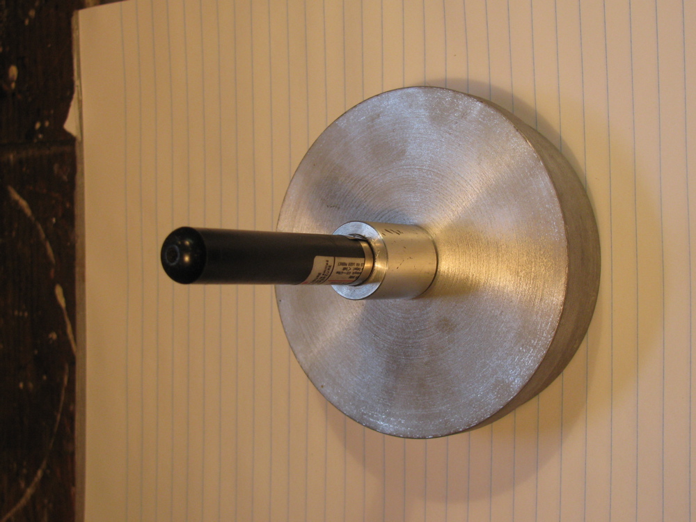
Took my time with my revised laser thingy and measured front diff and transmission flange angles. The pictures show the process. Laser on flange, measuring jig on other flange. I added a plumb bob to measuring jig to be sure it was plumb so that any lateral misalignment would show up (you can see the string in the pics). As it turned out there is very little sideways error in flange orientation. I remeasured the flange centre to centre distance as 1820 mm, and the vertical measurements are as follows:
Laser on transmission – dot 103 mm below centre of front diff. flange. This works out to be a 4.6 degree angle on the trans. flange.
Laser on front diff. – dot 83 mm below trans. flange. This works out to be a 3.7 degree angle on the front diff. flange.
The numbers are close to what I measured before, but I feel confident in these measurements. In the pictures the laser dot size seems larger than real life, and in one shot you can see the laser beam itself. The CCD in the camera must be sensitive to the wavelength of the laser.
Note: picture showing measuring stick on front flange and dot around the #8 mark is actually showing an erroneous first try, I had a bit of “schmumf” stuck between laser and flange, second try had dot further down measuring stick, and that is shown in close up pic.


Mark III laser thingy
Posted by albell in syncro specific repairs on June 17, 2010
Not being happy with how the laser pointer was held in the jig, I finally did what I should have done all along and that is use the laser’s own mounting bracket. The bit of aluminium angle bolted to the round jig gets clamped by the red bracket’s captured screws (not visible in pic). Now I can adjust the beam so that it is pretty well aligned with centre of jig. Previously the best I could do was a 1 cm circle, over the 1.285 m between flanges, when jig rotated on flange. The thing on the left is the crude reference jig that sticks onto the the flange opposite and shows the laser dot.

Again with the prop shaft
Posted by albell in syncro specific repairs on June 15, 2010
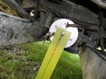
My last posts showed how the transmission flange is pointing down at a steeper angle than the front diff flange. I could not see a way of easily changing the transmission angle so I decided to shift the front diff. I supported the diff with a bottle jack and took off the front carrier and the rubber mount. You can see where the mounts go in the diagram, (No. 6). Looking at the mounts, I could see the lower mount was squished a bit.


So I swapped the thicker, or less collapsed top mount with the lower mount, and I added a couple of washers for good measure to help lift the front of the diff. so that the rear, where the flange is, would point down more.
I did a quick measurement with the Beall Angle Box, and the flanges were within half a degree of each other. My laser thingy showed that the angle had indeed changed, calculated out at approx. 0.65 degree difference…but I am not confident in my measurements. The electronic angle finder is sensitive to how it is placed on the flange and the laser pointer is not perfectly fitted at 90 degrees to the base so that it scribes a 1 cm circle when rotated. I have to refine my methods, but its close enough for the time being.
So I put the drive shaft in and took the van for a drive…. still a slight vibration at 50 kph (mind you, it is less than before). I left the bolts on the 2 rear most rubber mounts of the front diff. loose, wondering if the diff will find its happy spot during driving. No such luck. Will try again but with yoke bolts loose. Next “major” step is to go over lateral alignment.
prop shaft alignment again
Posted by albell in syncro specific repairs on May 24, 2010
Did another quick check on the transmission and front diff. flange angles, this time with my little “Beall Tilt Box” electronic angle finder.

Accounting for the the angle the van was sitting at (approx. 0.25 degrees) I measure a downward angle at the transmission flange of 4.90 degrees and at the front diff. flange I measured a downward angle of 2.50 degrees.
This is pretty close to the quick laser measurement (and subsequent trig calc. ) of 2.45 degrees and 4.45 degrees I did yesterday.
Time now to measure it with more care, using both methods, and then to see if I can adjust either the transmission or the front diff. angles so that they are the same.
God this blog must seem like the most boring place on earth… what an anorak I am turning into.
prop shaft alignment quick test
Posted by albell in syncro, syncro specific repairs on May 23, 2010
I had time today to do a quick check of the alignment of my prop shaft, or rather where the prop shaft goes, as I have it out right now…
I have to reiterate, this was a quick test, approximate measurements only. I attached my laser alignment jig to, in turn, the transmission output flange, then the front diff. input flange. Each time I measured down from the centre of the opposite flange to where the laser dot was. I also measured the distance between the centres of both flanges.
I did not measure any lateral alignment this go round.
What I found was the front diff was pointing down at a lesser angle then the rear transmission, 2.45 degrees vs 4.45 degrees. Ideally the angles should be equal and less than 4 degrees (but not zero degrees).
Here is a diagram of my results:

If you slept through trig, what you need to know is the TOA part of SOHCAHTOA. TOA means tangent = opposite over adjacent. For example in diagram above, for transmission flange, the tangent of the angle is 100/1285 -> 4.45 degrees. Just do the 100/1285 bit on your calculator then hit the tan-1 button.
Here is a diagram of how U-joints can be oriented:

You can see how my syncro is in the “W” bend form, but the 2 angles are not equal. The angles must be equal, or damn close, to eliminate vibrations. This means I have to adjust the angle that the front diff. sits by shimming the front mount.
Driveshaft alignment tool
Posted by albell in syncro specific repairs on May 18, 2010
Mark II of my laser alignment tool for driveshaft, more to come if I get off my duff and make a registering strip to show where laser dot lands. Inspired by Herman’s work (see blog role, Herman’s Syncro Project).

Syncro front diff. removal
Posted by albell in syncro, syncro specific repairs on April 3, 2010
Look, its cold and windy today, hail at times. I don’t want to freeze in my cold workshop so I am sitting at the computer, ok?
Courtesy of Kafer and Co., Homburg/Einöd is this pdf file showing how to remove your syncro front differential when you want to swap in that new or rebuilt viscous coupling. PDF with pictures, about 800 kb.
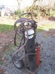
Webasto BBW 46 heater
Posted by albell in syncro specific repairs on December 8, 2009
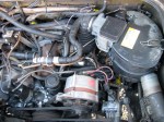
My ’86 syncro has a Webasto BBW 46 coolant heater, but unfortunately it has been disconnected from the coolant system and does not work. Why was it disconnected? I don’t know, so here starts another syncro adventure.
The heater is quite cool, has a control unit that will start the heater up at pre-set times, it burns gasoline to heat and circulate the coolant, and also turns on the cabin heater fan, thus warming the engine and the cabin. But it seems a fairly complicated affair to troubleshoot…
One thing I did discover is that the small, lipped, sealing ring between the heat exchanger and the recirculation pump has failed, maybe that is why it was disconnected? Local marine repair shop is hung down a replacement for me.
But I have heard that the unit really needs to be used regularly, this one obviously has not been used in a while, so even if I get the seal installed there is no guarantee the heater will work.
I’ll take some pics tomorrow.
Resources:
Gary Lee has one installed in his van, and link to repair manual (but its not a vanagon specific manual, and the vanagon install does have its own “qualities”)
webasto in vanagon, in German, again…
parts manual:70966B
Dec 9, evening, slapping unlabelled pics up:
Ball joint shenanigans
Posted by albell in syncro specific repairs on December 2, 2009
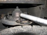
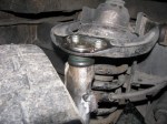
Over the last week or so I started hearing a slight knocking/clicking intermittent noise from front right of van. I had a look under van yesterday and found I could produce the noise if i bounced the front of the van. I narrowed it down to the upper ball joint by levering upper A-arm with pry bar (see pic), the joint would move and make the noise.
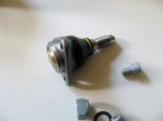
So today I set about replacing the joint. I looked at the manual and at Tom Forhan’s excellent description, bought a nice German ball joint, looked forward to one of those satisfying and straightforward repairs.
Oh, I did spray penetrating oil on the joint the night before, and also I heeded the warning on the ball joint box not to do this naked but rather wear overalls, a hat, and carry a huge wrench.
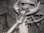
All went according to Tom’s instructions until I tried to “pop” the joint out. No way would it budge. Ideally what happens is that you drive the pickle fork in then strike the side of the assembly the joint goes into. On the syncro there is a suitable flat on the aft edge of the steering knuckle. I was using a 4 lb hand sledge. I ended up destroying the socket part of the joint leaving the ball part firmly in the steering knuckle. Believe me, I whacked that bugger a lot.
This was the time in these kind of jobs where the calm demeanour turns into hatred of mechanical things. Time to get the torch. I didn’t really want to heat up the knuckle, I thought that heating the ball then pouring water on it would break whatever unholy bond had been formed. Nope, still no luck. Finally broke down and “gently’ heated the upper portion of the knuckle, not red hot mind you, and then the pickle fork would drive the bugger off.
Installation of the new joint was simple (and slathered in anti-seize), apart from the fact that you have to hold the end of the threaded shaft (12 mm wrench) from turning as you tighten up the nylocked nut. Only closed ended 15/16” wrench (my 24 mm substitute) would fit and even then only allowed a few degrees of turning, grrr.
All this took 4 hours, including a few calming down breaks.
I’ve included a pic of my “Jack-All” high lift type jack with my home made adapter that fits in the vanagon jacking points.


Prop shaft R&R update
Posted by albell in syncro specific repairs on November 27, 2009
to recap… purchased ’86 syncro this last summer, prop shaft out because of vibrations, vc was assured to be ok. U joints on prop shaft looked suspect, but i installed and yes, vibrations at 50-60 kph. Also vc was weak, not passing the 2×4 test.
I replaced u joints on shaft (precision brand, #813, see earlier post), checked the fit of the shaft and bushings on guibo end (nice and tight), and popped shaft back in. Still vibrated at same speeds. Loosened front diff mounting bolts, drove around, no difference.
Removed shaft, examined u joints, one was loose so I replaced circlip with thicker one (u joints came with 2 sets of circlips). Checked bushings and shaft fit again.
Two days ago I put it back in, but before it was installed I did a quick check on vc by using the volvo method outlined on testing vc post. I got a value of 17 ft/lbs. Not much eh? Confirms vc is weak.
It would would be interesting if others would do this simple and quick test and post results, I bet there is a range of values.
Oh, and as well as putting prop shaft back in today, I replaced the dodgy Uniroyal Laredo tires the van came with with some Nokian Hakkapeliitta CS tires.
Road test: tires louder and firmer. Vibrations almost gone, A very slight vibe at 50-60 kph, but its very slight and not bothersome (that said, I will work to eliminate it).
Mud test: on the farm here there are ample spots to get stuck, and it has been raining pretty hard the last 2 weeks. Last week with prop shaft out and the Laredo tires on, I tried going up a curving, maybe 20% hill, grass and clay/mud. I never made it, even with rear diff lock on. Today, with much wetter conditions, I made it up no bother, and no diff lock.
i toodled around lumpy, uneven, sloping ground, grass over North Saanich clay. Didn’t get stuck, but the front wheels didn’t “feel” like they are doing much.
Conclusion: prop shaft vibes mainly due to “loose” u joints, either when they were old worn out units, or new ones, not installed with correct circlips. The “off road” performance I attribute mainly to the great tires. Perhaps the vc is allowing a little torque to get to the front, probably wishful thinking.
Testing the viscous coupling
Posted by albell in syncro specific repairs, vanagon tech papers on November 20, 2009
I’m just going start dumping links here that relate in some useful way to understanding how to test the function of a viscous coupling such as installed in the Vanagon Syncro.
Derek Drew’s comprehensive analysis and test procedures.
syncro.org page. Not sure about conclusion derived from graph of viscosity vs. heat though, but still good info here.
Volvo vc test, in car, interesting – FHPs_SB46-0005-0101
Natterings on the North American Subaru Impreza Owners Club, extracts from a SAE paper on how the VC works (not bad, still does not fully explain how the plates are forced together in the “humping” stage, its still a mystery). This Subaru site has a few discussions about vc function and testing, its worth a look around.
“Out of car” testing of a Subaru vc. Autospeed article.
Test for Landrover vc described here at transmission specialist. Look under “technical information”
Syncro prop. shaft R&R
Posted by albell in syncro, syncro specific repairs on November 20, 2009
This last summer I replaced the original u-joints in the syncro prop. shaft. The previous owner had removed the shaft for the summer, but told me there was some drive line vibrations. There are a lots of tales of woe and intrigue on the net about prop. shaft vibrations, causes and cures, so I decided to have a go at fixing mine. First thing was to replace u-joints. Stock VW joints are expensive, so I used the same replacement joints as Herman did on his syncro project (Precision brand, part #813). The bronze bushings that the yoke assembly and shaft fits into at the guibo end of the shaft seemed ok, the shaft fit in snugly. I just re-greased that, installed the new joints (blanking off the grease nipple fitting holes – I couldn’t get a nipple to fit in the tight spot, you’ll see what I mean if you ever do this job), and then painted the shaft. I re-installed the shaft and still had drive line vibrations at around 50-60 kph. I tried the trick of loosening the front differential mounting bolts and driving the van to let the drive line “find its sweet spot”, but that did not work. I removed the prop. shaft and re-examined it, and noticed some play in one of the joints. I removed that play by installing a thicker circlip (new joints came with two sets of circlips, differing in thickness).
That seemed to have removed the play. I double checked the fit of the yoke shaft into the bronze bushing, was ok.
The next step is to make sure transmission output flange and front differential input shaft are aligned to specifications. They are supposed to be aligned longitudinally, but each flange can be pointing down slightly, 4 degrees or so. I have made a laser alignment tool and I need to get under van and do the deed. One thing that has slowed me down is my suspicion that my viscous coupling is weak, but that’s a story for another blog entry.
Meanwhile have a look at the old u-joints. Notice the pounded marks on one of the bearing surfaces! (apologies for the blurry pic).

