Archive for category vanagon mods
Vanagon – dash foil replacement
Posted by albell in vanagon, vanagon mods on July 30, 2022
Good friend Greg has replacement dash foil in the works. Made from better materials than the original, a very nice bit of work. If you are interested , check out this survey form he created to determine numbers to make
https://forms.gle/MYNDQiHYLuG1rZMQ6
Vanagon – stock fridge vent delete option
Posted by albell in vanagon, vanagon mods on July 23, 2022
I’ve installed a Dometic CRX-50 fridge. Yup I finally let go of the propane fridge I’ve been faithful to for 20 years. The install pics may come later, but the fridge vent replacement is now.
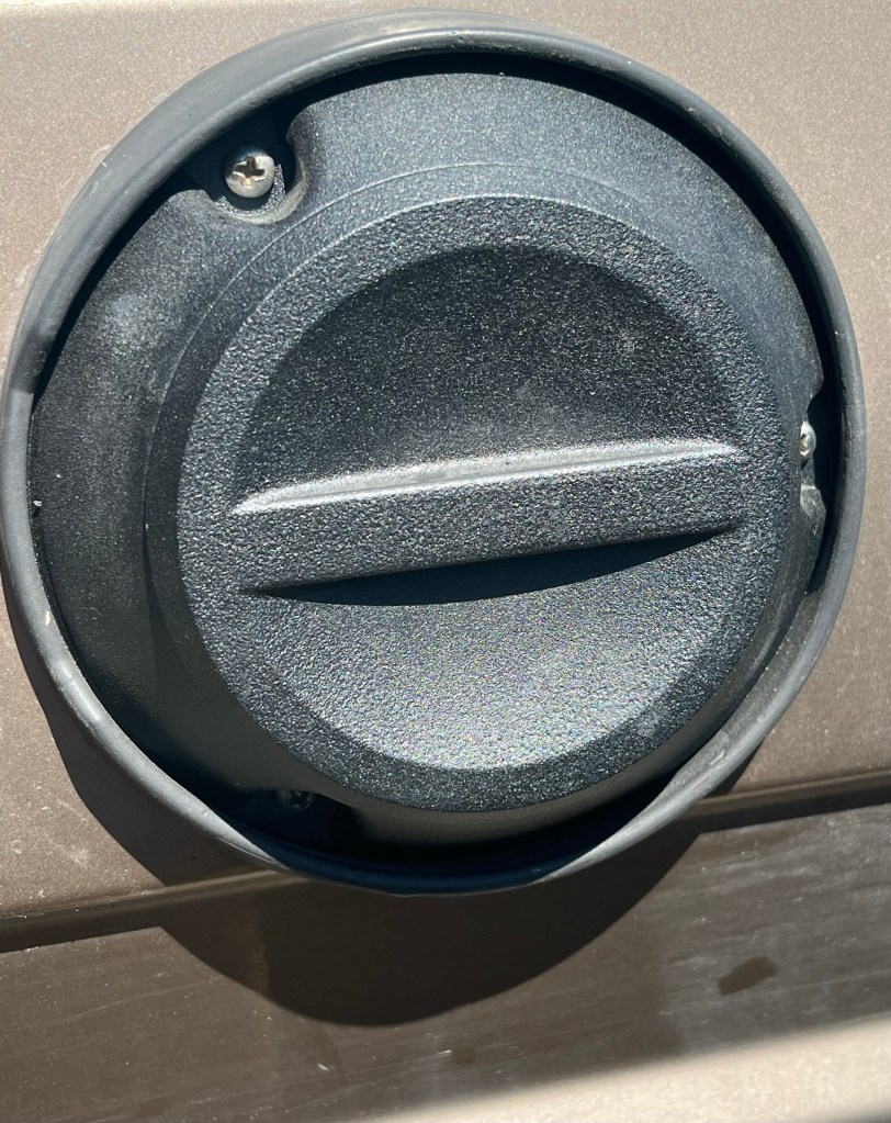
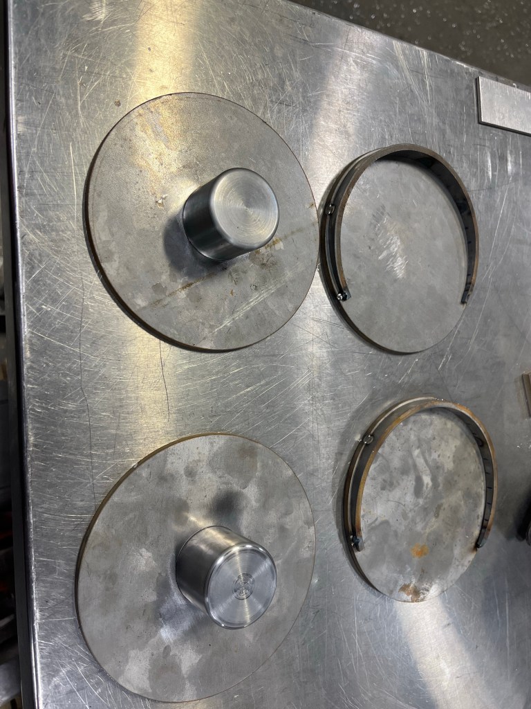
Made an aluminum thing that approximates the stock vent dimensions. Has a lid with magnets that correspond to magnets in main body , north south opposed.
I kinda had issues with the magnet placement, you’ll see the marks, but the concept works, a twist on the lid and it comes off.
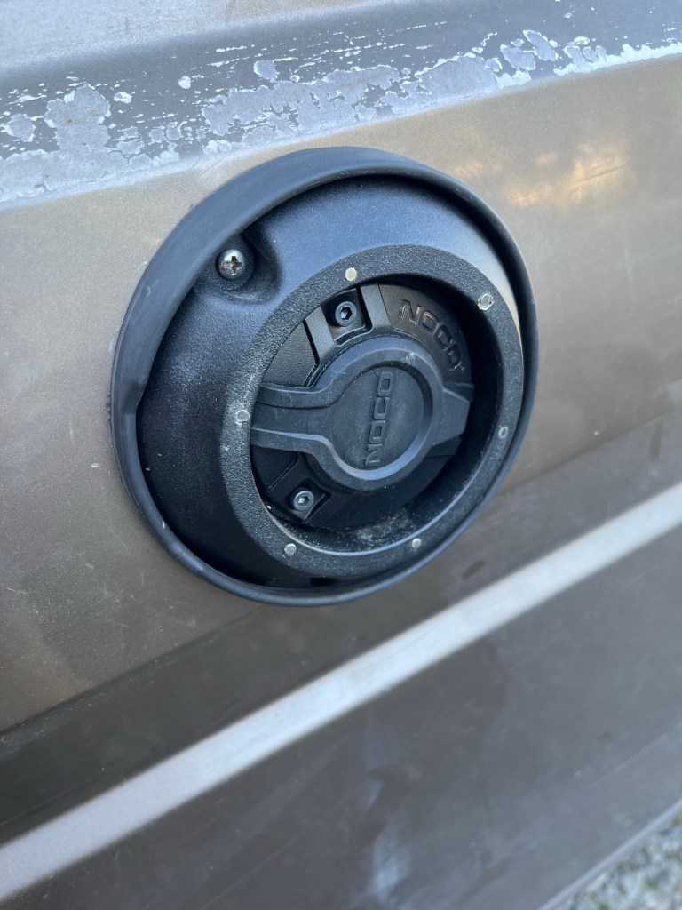
Inder the lid is a Noco 120V inlet plug. That goes to the fridge ( has an AC power option). If I were to do it again, and I’m probably going to, I’d use larger and fewer magnets, and try not to screw up on the magnet hole drilling!

.

Vanagon – trailing arm replacement
Posted by albell in syncro, vanagon, vanagon mods on July 23, 2022
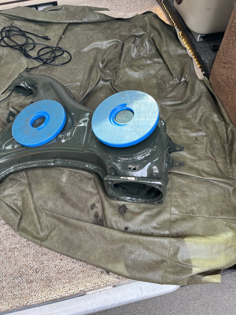
Not much to say here. I replaced my trailing arms with a pair I refurbished and modified, I ground off the spring perches and welded up new , thicker, and angled perches. Also made some thicker plastic pads to go on them. Primed and powder coated the arms and installed polyurethane bushings.
Made the angled perch. The lens shaped part,waterjet cut flat, then I just hammered into a roughly circular shape. Welded to top and bottom flat disks. The central boss welded in too. I drilled and tapped the top plate for a 5/16” set screw. That way I could squirt some rust inhibitor into that space after the arms painted. Also put in a couple of M6 riv nuts in arms to hold a clip for the brake hard line.
The blue plastic spacers I made from some mystery plastic that was hanging around. I think it’s nylon. Let me add this…
The reason I made the thick plastic pads for the perch was to be able to machine a recess for the spring end. The stock pad as you know, has a formed recess, with a corresponding thin and formed plastic pad. Those stock pads are hard to get, the replacements from vendors seem only to be plain plastic discs, no recess. I didn’t want to machine the metal for the recess if I couldn’t find a plastic pad to fit… get what I’m saying?


Not shown is new springs and slave cylinders in the brakes, new ( well a used 2wd ) handbrake cable on the passenger side wheel, and new brake flex lines. I did manage to bend the passenger side hardline into an ugly mess when doing that side flex line, but the little blue plastic clips ( yeah I made those) helped pull it back to reason.
The combo of the angled perch and thicker plastic pad has resulted in a height of about 19.88” from fender lip to hub centre. That’s at the limit, I think, of amount of lift for stock axles and joints.
Did the swap in my driveway, on gravel. I’m too old for this type of thing now, I felt every minute of the job.
Ok Simon…
Vanagon – “The Swellegant Junior” sneak peek
Posted by albell in vanagon, vanagon mods on July 20, 2022
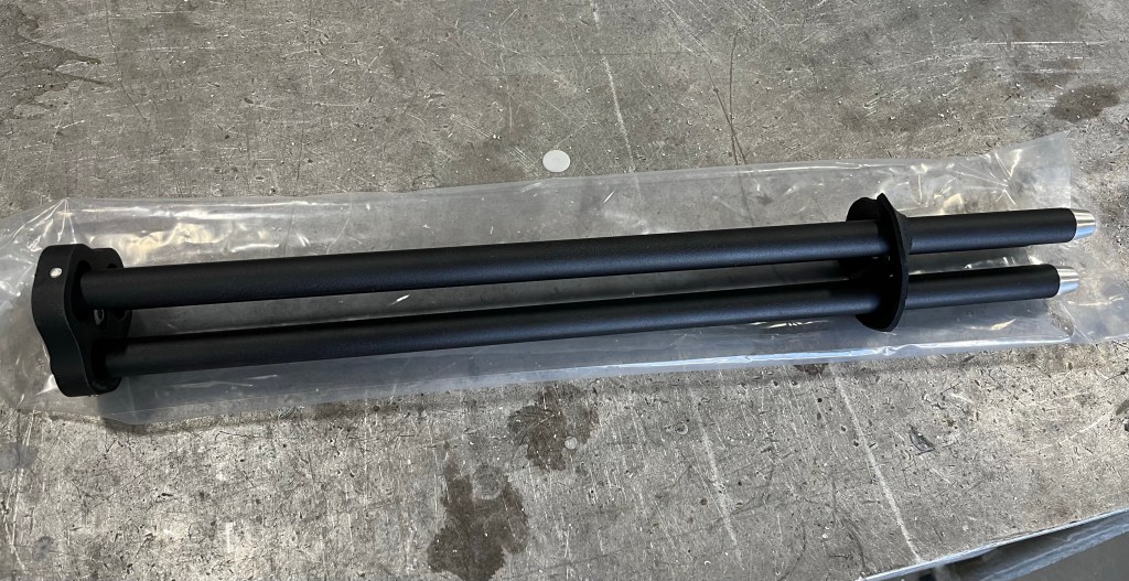
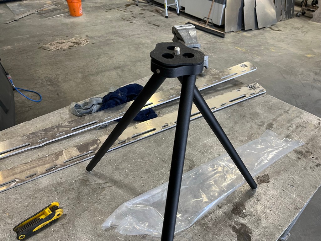
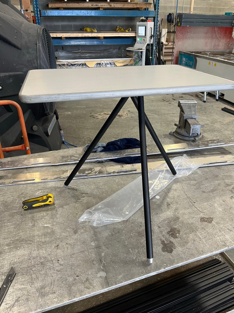
Some of you may know I’ve been working a few versions of a table stand that uses the stock westy table, since about 2016. The idea is you can screw on your small or large westy table to the stand and have a place to put nibbles and drinks when sitting at the campsite.
This is the latest iteration. 6061 aluminum, stainless pins and screw, and powder coated black. It is designed for the later westy tables, the ones with the thread hole in metal plate on the underside. The earlier version table with the tube on the bottom…. Well I have a prototype adapter made, but not tested.
Has a rubber gasket that holds the legs together when folded, and when in use , the gasket goes between the table and the stand to give firm adjustability of the leg orientation.
This is a luxury item. It’s expensive to make – cnc machined, quality materials, and living wages.
But it’s excellent , and it works!
And the price…
$150 Canadian
Here are some pics taken in the workshop.

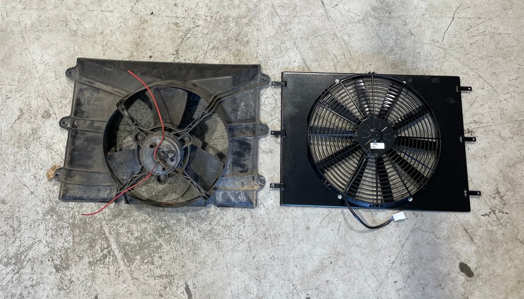
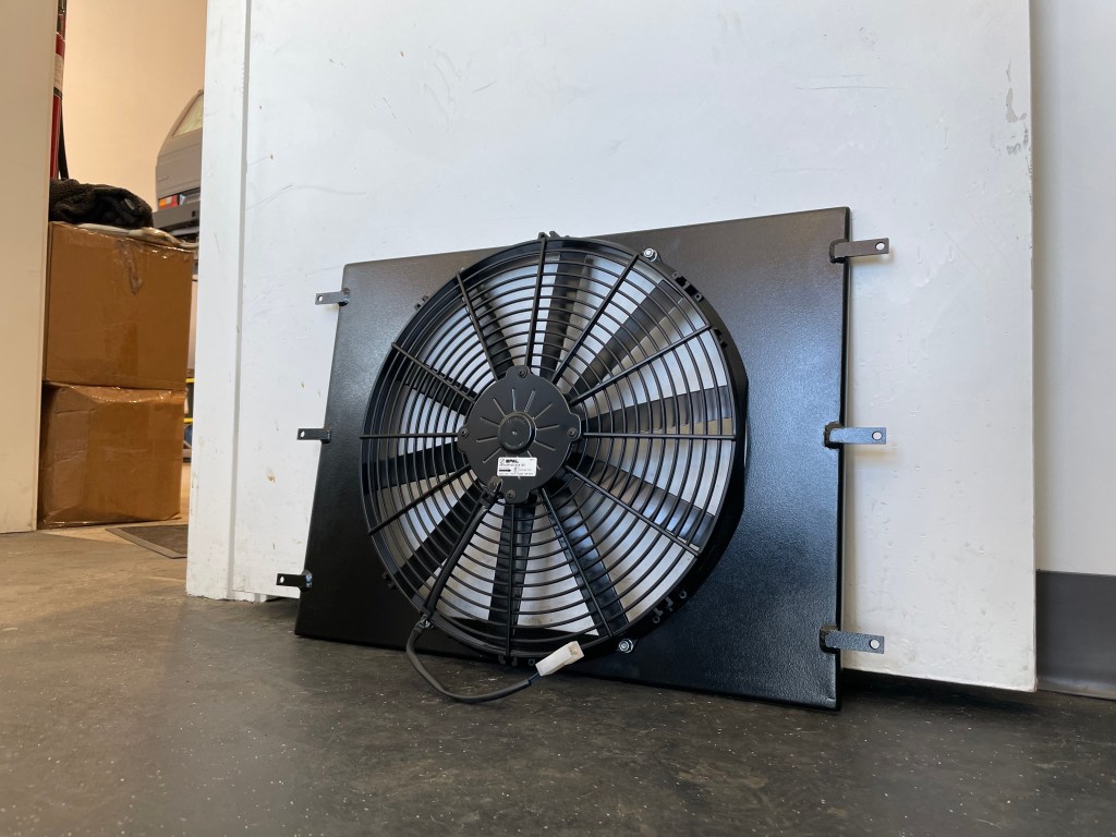
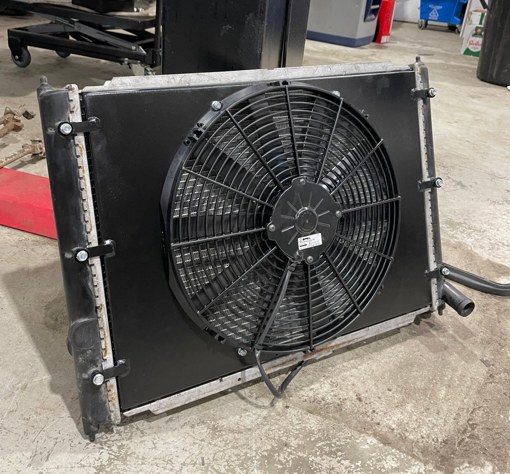
Vanagon – a slim radiator shroud and fan
Posted by albell in vanagon, vanagon mods on July 18, 2022
Made a shroud for Quentin, his design I’m just the fab guy. He has reasons for wanting slimmer.
It’s quite a reduction in thickness.


Vanagon – stock westy kitchen light improvement
Posted by albell in vanagon, vanagon mods on July 18, 2022
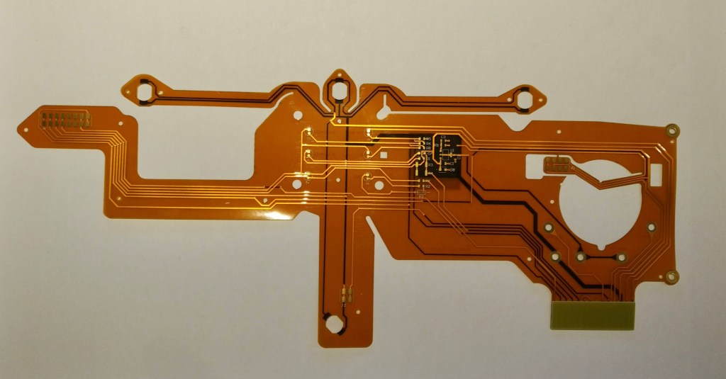
Friend Greg has developed a snap in replacement for the three halogen festoon bulbs in the westy kitchen light.
Led strips and dimmer control integrated on a board that really does just snap into the bulb holders on the stock light unit.


That spring on the left is the dimmer control. It rests in the stock shade and allows touch dimming.
Friend Simon got one and tried it out. He made a wee vid which explains how it installs and works. Have to note there are camera artifacts , you don’t see those in actual use.
I have to say, this unit is superbe. It’s so easy to install and the light quality is excellent. I think it’s a no brainer for those wanting to retain the stock light but move up to lower power draw led, with good light quality.
I think at max brightness the unit draws 1 amp, at lowest setting 70 mA.
Oh and I should add, he’s selling them.
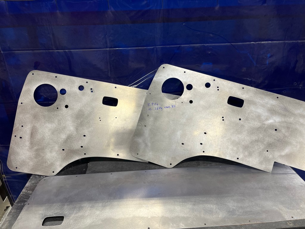
Vanagon – door cards
Posted by albell in vanagon, vanagon mods on March 22, 2022
It’s been years in the making. I’ve never got around to it until today. 0.090” aluminum. Some mods done too. I’ve cut the stock speaker hole larger and will attempt to fit larger speaker. That does have some challenges but I think I can do it. Also added smaller hole beside that main speaker hole for tweeter. Did the back hatch card too and added cut out for hatch release using the stock front door lever assembly.
I scuffed the cards up after cutting. If you look closely you can the my weight measurement written on one card. Comparison with bone stock 82 vinyl covered card.
Oh, what I used…
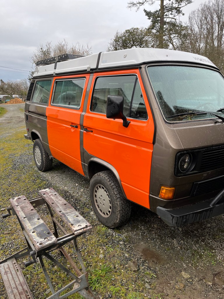
Vanagon – when I’m old I shall wear orange
Posted by albell in syncro, vanagon, vanagon mods on March 20, 2022
One of the few *good* things about getting old, you care less and less about what people think 🙂
Vanagon – trailing arm rebuild part two
Posted by albell in vanagon, vanagon mods on March 20, 2022
I had this thought that I’d make modified spring perches. To replace the rusty stock ones I pulled off, and…
This is where I doubt my thinking. The spring perch is really at an awkward angle when the trailing arm at fullest low position. I’m sure it’s more aligned with the upper spring bump stop when fully compressed. But I thought I’d cant the spring perch a little to make it align “better” with spring when trailing arm at a more neutral position.
You probably know that the diesel 16” Syncro had wedge shaped aluminum spacers on the spring perch to do the same thing. But I’m guessing it was more to accommodate the change brought about by the 16” Syncro longer trailing arm.
So it’s very debatable if what I’ve done is wise or needed. But hey ho! Off we go.
Perch made from circles of 3/16” steel. I modelled a tapered spacer from same stock , and made developed shape to cut out. I just hand bent it to slightly smaller than the discs, welding allowance.
Tacked up , you get the idea


Tacked, getting the idea now?
With an extra home made plastic pad, had milled in recess for spring pigtail. That’s about 1.5” at the back. I can make thinner plastic pad if this is too much of a lift. The pad as is, 1/2”.


I put some rust converter on the trailing arms and plug welded the three holes under the perch. I didn’t attempt to fill the divots left from drilling out the spot welds that held on the original perch

And then clumsily mig welded onto arm. I’ll drill a hole in the sandwich and squirt in some waxy stuff for rust protection. Then weld up the hole.

I don’t know if all this is a good idea. But I did it 🙂
Next is to pop in some m6 riv nuts that I’ll use to secure clios for both the brake hydraulic arm, and the e brake cable. I’m thinking about welding closed some of the seam area left open from factory, not sure about that though. And I might shave the seam for more tire clearance, as the kids are doing these days ( I did that on the pair of arms I gave to Simon). Apart from that the next steps are another sandblast then powdercoating .
Vanagon – syncro transmission rebuild
Posted by albell in syncro, vanagon, vanagon mods on March 12, 2022
This is Quentin’s work, he’s at Vivid Vans. A series of pics with his comments interspersed. I’m envious.
Teardown:

You can see the make shift m5x.7 puller I made for all the idler shafts to the left of the housing. An m6 bolt ground down and tapped to m5 haha. You can also see wear from axial movement of the mainshaft bearing in the casting.


I took a photo of each gear with its respective syncro for easy reference at reassembly. You can also just go off the number of teeth but it was easier for a newbie like me.


Nice and clean after being glass bead blasted and thoroughly cleaned.

Test drilling old diff housing for pinion oil squirter. Right on the money first try. (housing was trashed)


My NOS S.A. aluminum diff housing I had modified by Mr. GAS in Colorado for a locker and extra material for the pinion bearing squirter. Yes it would have looked a lot nicer if I had it milled down but I ran out of time.

AN4

4th Gear cool oil bath squirter. Questionable effectiveness but doesnt hurt nonetheless. Bathes 4th gear in cooled oil.

Main bearing oil squirter. Squirts cooled oil directly into the main bearing from the front side.


Main bearing retainer plate. South African style reproduced by Alika Motorsports. Prevents axial play. (I had the wrong thrust bearing pressed into the housing please ignore! Fixed it the next day.)

Cut the oiling groove in the pinion race using my CNC angle grinder. Drilled with 1/8 carbide drill bits.


Setting up the ring and pinion with the help of our head Tech Tony. Didn’t get photos of final pattern but It was spot on. Probably the most difficult part of the rebuild.


gear stacks assembled. I literally spent months labouring over the gearing. Ended up going with:
3.333 First
1.82 Second
1.125 big tooth Third
0.75 Straight cut fourth

Deleted the reverse/granny syncronizer and installed a 2wd slider instead. TDIs have been seen to rattle the syncro assemblies apart and destroy the low/reverse housing.

Fully assembled all aluminum goodness

Painted, torqued, ready to thrash. I just need to plumb the oil cooling circuit and it will be ready for break in.

One last photo of my trans temp gauge I custom built. My oil cooler pump is activated manually by a 2nd defroster switch. I considered doing and automatic cooler set up, but your brain is the best automatic controller money can buy.

Vanagon – start of trailing arm “rebuild”
Posted by albell in vanagon, vanagon mods on March 10, 2022
Years ago I had a pair of trialing arms which I fixed up for good friend Simon. I shaved the wheel side seam and welded in a reinforcing plate in that area. Also welded up the spring pad perimeter. He finally had them installed last summer. His old ones he gave to me.
They were heavily coated in tar like undercoating and had been quickly cut from the van. I burdened off the undercoating using a tiger torch, and also got the bushings out.
Had them sandblasted. Here’s what one looks like after that. You might be able to see the Zip disk cuts in the arm, and the bent tabs. No idea what that tab on the inboard bushing area is for.


I welded up the zip cuts, and then I drilled out the spot welds on the spring perches. Yup, that’s what it’s like under the pads. Even though though the arms were rust free, on the surface, under the pads it’s nasty.


I’ll go out on a limb and say, unless you’re living in a super dry part of the world, your good looking spring pads will have cracked paint and rust under. Just saying, not being a Cassandra 🙂
Vanagon – funny Trucklite headlamp behaviour
Posted by albell in vanagon, vanagon mods on March 6, 2022
Hi, I bought another, yes another, set of cheap led headlamps. Let’s not get into the pros and cons of that just yet. I’ll report on those later.
But I had the chance to compare quickly, the new ones with some older Trucklite headlamps. They differ completely in the led arrangement and number. But when I was doing a quick comparison ( very quick , shining onto a welding curtain) , I noted the Trucklite unit had a delay switching from high beam to low. You can see in this shaky vid. Trucklite on the right
Vanagon – quick autopsy of GW throttle body
Posted by albell in vanagon, vanagon mods on March 6, 2022
It’s from the burned out orange van. Engine fire so you can imagine all of the plastic parts in there are melted or burned up. I did manage to pull the throttle body and it’s a go westy one. Here it is, even after an hour in the ultrasonic cleaner. I’m guessing it was black anodized.

Took it apart. The bearings , sealed, 22mm OD, 8mm ID, 7mm thick, we’re toast of course. And the throttle position switch burned off.


I did my best with scotch Brite pad on the main body and I skimmed a couple thou off one end ( lathe). The small parts I used vibratory tumbler, mix of walnut shells and grit. Put it back together using a a pair of cheap ceramic open bearings that I had. Of course you should use sealed , ti reduce the air bypass along the shaft.
Couple of notes. It’s a well made thing. I’m impressed by the build quality. The shaft has a very small groove where the bearings sit. There was something in the groove but maybe not an o ring, maybe it was some sort of sealant. The butterfly is a simple flat disc, no ramp or bevel as in the stock plate. The fit in the bore is very good, very close.


Good friend Greg has one in his van. He says it’s great. I don’t doubt it, it’s well made.
I’ll keep this one for a spare, yes I’ll swap out the bearings and see about something with that tiny groove in shaft under the bearings. And I need to get a tps either a kit from the usual sources or make one up. I’d did notice GW kit uses a 3D printed cam.
Vanagon – home made muffler update
Posted by albell in vanagon, vanagon mods on August 20, 2021
I made a muffler eight years ago. Here’s a link to all the blog posts about construction then.
https://shufti.blog/?s=Muffler
Since then I’ve added a working cat, and new exhaust pipes. But I’ve also hit the muffler a few times on rocks and snow banks. Hit it enough that I cracked the weld at the tail pipe end of the muffler.
So when the engine was out recently I cut that end off and re-welded. Gave me a chance to look inside and see how the stainless steel swarf I used as muffler packing was doing. Was a little sooty, not much, a little discoloured by heat, but overall surprisingly good. Don’t know why I was expecting any different.
Gave the muffler a bit of a buff to take off dirt and shine it up a little. Also made new hangers. Same style as before but stainless pins to hold the band clamps instead of aluminum. It’s 3/8” aluminum, 1/2” diameter on the pressed in pins. Oh and new band clamps.


Sounds more or less the same as before. Yes, louder than stock.
Vanagon – new fridge knobs installed
Posted by albell in vanagon, vanagon mods on August 18, 2021
Had to pull the fridge out a bit. Was it worth it? Meh…


Vanagon – replacing rusted rear spring perch
Posted by albell in syncro, vanagon, vanagon mods on August 14, 2021
Recently noticed the right side trailing arm spring perch was rusty, lifting from arm and the bump stop hanging on by a hair.
I think I showed the perches I made in recent post. Pretty well copy of stock except no flange on top of bump stop. Don’t know why I didn’t make flange.
But here are all the pics I have of the perches I made. Approx 1/8” steel, bump stop made from solid stock ( no right sized pipe handy) hollowed out a bit. Welded to plate on back side . Hdpe on top, with recess for spring pig tail. Those counter sink holes are a mistake, thought I’d screw plastic to the plate… no need .

Anyway… today I took van to work and got on with the rusty perch. It was ugly. Lifting at the rear. The plate is held to the arm by spot welds. So it’s common for rust to get between plate and arm. I thought I’d got all the spot welds with drill, but missed one. Chisel and hammer was the motivating force to lift the plate. Then power wire brush and flap disc.


I cleaned that mess up more. All the rust. Treated with rust converter. Ground down to metal around perimeter and clumsily welded on the plate. primed and painted. Notice the holes… why? I have no idea why I wanted plug welds in them. I tried but the rust preventative coating I put on… made welding not nice. So I stopped. Oh but before I welded the perch on I drilled and tapped the bump stop. Put a set screw in for now. I was worried I needed the flange that’s on the stock bump stop. The tapped hole makes it possible to screw on some facsimile if needed.

And plastic on , spring on, etc etc.


It all works but I’m not happy. Recently found out that the euro 16” Syncro had and angled aluminum spring perch, matched the spring angel better. I wish I had known this before. It would have given me more confidence to do what I had a notion to do. I need more courage. And I was considering a swivel spring perch. But no, I could have, but didn’t. Coward.
But it all works, good enough for now. But I’m not happy. Things can be made better.
Vanagon – LED headlight H4 bulbs, next chapter, Part 1
Posted by albell in vanagon, vanagon mods on October 17, 2017
Last winter I installed some LED H4 bulbs into my e-code lamps. Here is the link to the last update about them. If you haven’t read that post, and the original install post referred, and you want to know my reasoning behind trying the bulbs, I urge you to go read them.
Oh and another proviso, I bought both the original and these new versions from Banggood. They weren’t given to me. My opinions about the bulbs are not influenced by any freebies.
So why did I buy new bulbs? There are three reasons. First one is I was not happy about the radio interference they caused. The interference affected weaker fm stations. It was annoying. Secondly, I wasn’t satisfied about the high beam projection. The beam seemed to get lost at distance. On the other hand the low beams are so good that I didn’t need the high beams as often as I did with halogen bulbs. Again, please refer to the post linked above for more on beam patterns. The third reason for trying another set was that these bulbs come with optional gel filters, yellow. I was curious about how they would work.
Ok then, here are the new bulbs, and here is a link to the product page. Link fixed, sorry about that.

Packaged pretty well.

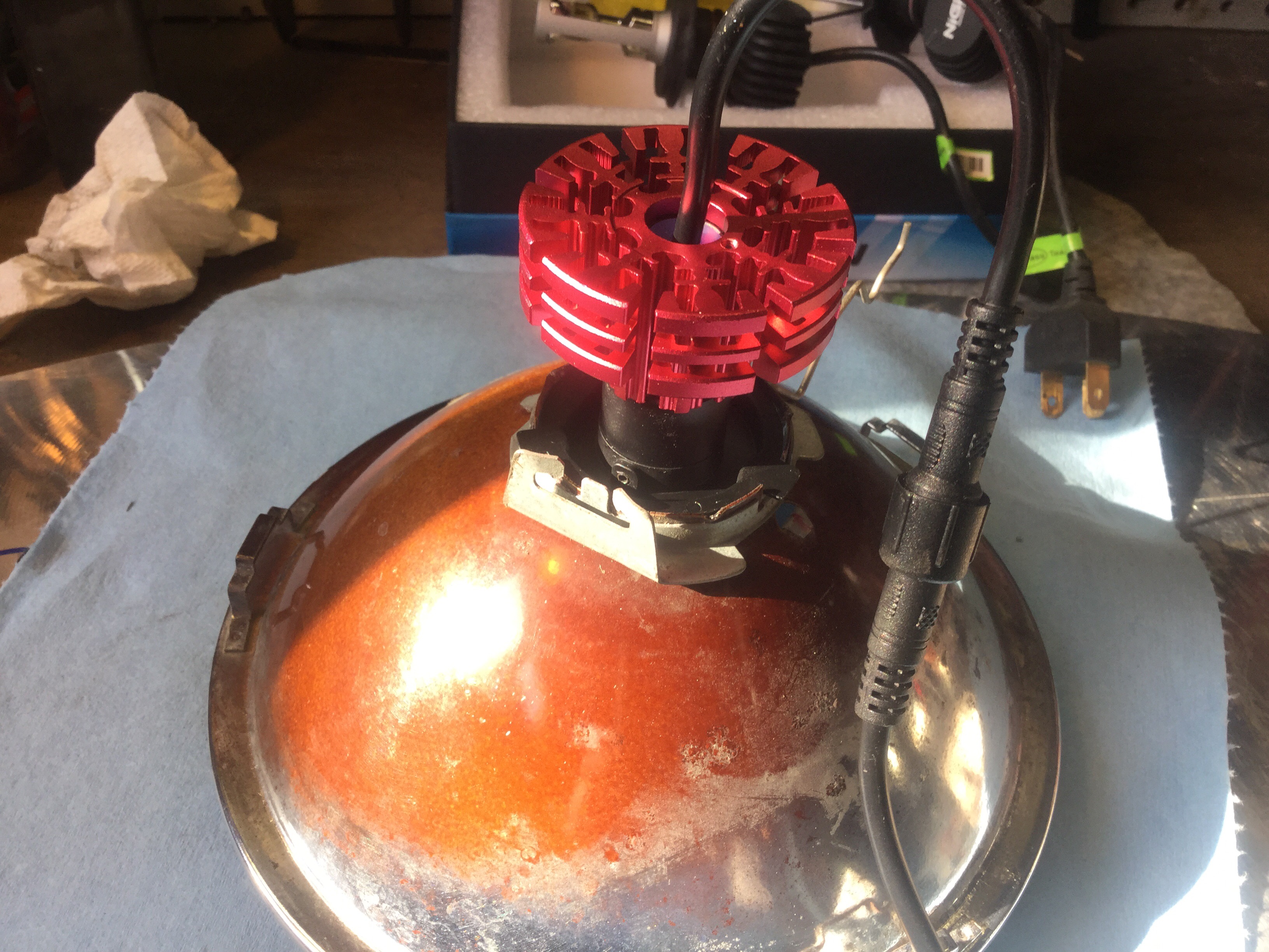
Similar to the older model ( on the right ) but with some important differences.

Right away you see the heat sink is different. I think that the older bulb has some electronics in the base, the new ones have a separate box of electronics. And notice the difference in the led element, size, number, and orientation.

I’m going out on a limb and say that the newer bulb has the LED elements arranged to more closely mimic the filament positions in a halogen H4 bulb. Interesting that the elements are smaller and fewer but the bulbs are advertised as 30W each compared to the 25W of the older bulb.
The new bulbs have a metal box in the power line. I was surprised it was metal, made me hopeful that the radio interference issue might be fixed. Popped the cover to have a look.

Components are potted, only a cap showing.

I was impressed, I started to think that these bulbs were surprisingly well made. The power line has a very positive and o-ring sealed connection. This probably eases some installs, makes no difference in the van.

The filters, according to the instructions, are self adhesive and applied to the glass tubes.

I’m holding off on the filters for now, but I did install the glass tubes. The end of the bulb unscrews and the tube slips down and seats against an o-ring.

O-ring wasn’t in correct position in that last pic, but here we go fixed.

Another interesting feature is the rotationally adjustable mount. The three tab base is held in place by two set screws, and it can be rotated. There is a degree ring on the base and a witness mark on the bulb body. I did not change the orientation, I’ll wait for some night testing to see if it’s needed. I’m only guessing right now about what effect the rotation would give.
Time to pop them into the lamps. The older bulbs thicker bulb body didn’t let me install those rubber boots, but the new ones did.

Here is new bulb without boot.
 If you remove the three tab mounting base you can push on a boot and then reinstall the base. The boot is everted here, makes it easier to get at the set screws.

Keep the boot rolled back and carefully get the retaining wire bails clipped in.

Then pop the boot.

Ok, so I actually installed one lamp last night. Right away I saw that the beam pattern on the garage wall was tighter, both low and especially high beam. The radio interference problem was still there, grrr.
But today, with both bulbs in, the interference problem has disappeared! Yes, that’s right, weak fm stations now back on the menu. I’m really chuffed about that.
Next to do is swap one of the old LED bulbs back in and do a comparison, take some pics etc. So far I’m really pretty impressed by the build quality of these bulbs, especially for Can$64.
Vanagon – alternator voltage regulator re-brushing
Posted by albell in vanagon, vanagon mods on October 1, 2017
During the summer, on a camping trip, the alternator failed. The brushes on the voltage reg finally wore out. I had a spare (used) voltage reg on board and the swap got us going again.
The failed regulator was an adjustable unit I bought way back in the early noughts. It got swapped over from my old 82 westy to the Syncro in 2011. It had been working perfectly all this time and I really liked the ability to up the voltage output a little to overcome any voltage losses in the wiring up to the battery and also to give my batteries a good charge.
I think the reg cost around 35 bucks back then, haven’t checked the prices these days. Might not seem cost effective to repair it, but I wanted to. Hey why not? What’s the point of other folk posting how to do it…
Local automotive electrics outfit, Brian Roberts, sold me a pair of brushes for 8 bucks. Just $8, a little solder, flux, and time, and the reg was fixed. I wasn’t very good at documenting the steps but here we go.
The new brushes look like this, carbon-like with a braided copper pigtail. The spring is the old one, no problem re-using.

Old brush…

To get the old brushes out, well originally, under the solder, the metal is formed into a tube which is crimped onto the pigtail, soldered, and trimmed.

I found that merely melting the solder didn’t release the pinched pigtail. So I drilled it out. That meant when I inserted the new brush and pigtail I had to hold the braided pigtail…

Pigtail with spring fed up into the brush holder on the reg, haemostat holding pigtail so brush projects fully but doesn’t come out. Then, flux (rosin) and a good strong iron.

Was hoping for a better blob, but it’s ok.
And the iron? This old Weller, it’s a champ with this sort of thing.

Same thing with other brush. Then trim the excess copper

So that’s all good. Hey just as an aside, clean up shiny, all the contacts on the reg and also on the alternator body.
Acesss to the lower machine screw holding the reg to the alternator is fussy in the stock wbx. An intake runner impedes screwdriver.

An offset screwdriver does the job, albeit slowly. But beware, if you didn’t disconnect the battery then you can hit the hot stud on the alternator with the driver. The angry pixies make you jump. Foiled a second attack with heat shrink on the driver. But the pixies managed to nibble one end, see?

Oh, btw, adjustment of the reg is done via little screw.

Dialed mine up to 14.65 V at alternator. But I’ve noticed that the voltage will drop maybe half a volt or so when the alternator heats up. Btw, the multimeter is pretty good for $15, banggood. Auto ranging, back light, big display, AA batteries rather than 9V. Still have the protective film on display, it’s not a thing with me, just forgot.

Vanagon – minor changes to old mods
Posted by albell in vanagon, vanagon mods on July 22, 2017
A while back I made an aluminum grill to replace the stock grill on the rear side of the kitchen unit. I made it such that it would house an USB dual outlet and a voltmeter. Later I rotated it so the outlets were in top.

It was ok, never did paint it. What bugged me was no switch to turn off the voltmeter and outlet. So with more enthusiasm than design skills I made another and this time added switches and painted. Btw I used krylon espresso brown which I was told was a good match for the brown in my older westy cabinetry. The pics don’t really show the colour well but it’s darker than stock.

That thing in the aluminum block is a digital controller I’m using for the fridge fin fan(s). More on that when I post my findings about my fridge mods. Yeah you can see a bit of sloppily applied insulation on the fridge exhaust pipe, that’s much less than originally installed. Again, more on that later.
Now I can switch on the volt meter and USB outlet. The thermo controller has its own on/off function. Extra switch thrown in there just in case.
I did make the vertical slots as long as I could, but I didn’t mean to slightly overlap the cabinet. Doh…

Also refined, ha, the “new style westy table on old style arm” mod, link and link, slimming the aluminum adapter down a tad and adding a plastic spacer, ( the red thing, don’t know what kind of plastic, might be Delrin).

Surprisingly, the plastic spacer improves the tightening action.
And back to that espresso brown paint. I painted the little indicator panel on the kitchen unit front face. Maybe you can see the colour mis match in this pic. Nothing quite like taking a picture of something to make you realize just how beat up a thing is, man, look at those dents etc. Oh and another thing, trying this and that to bring back some life to the rest of the face plate. Paint was chalky and faded.

Vanagon – that clunky airfoil roof rack update
Posted by albell in vanagon, vanagon mods on July 5, 2017
Last year I made a pretty clunky roof rack to hold my old Thule ski box. Seemed like a good idea at the time, using up some airfoil aluminum extrusion. But, and apart from my crappy welds, I think the end result was a bit off. Here is the link to the original post. At that time I was using an aluminum rail attached to the side of the pop top, it worked but I thought it flimsy.
So… I made some new side rails from 1″X2″ aluminum box section. The rear Most section is bent to fit the contour of the roof, and I put in some slots for visual interest and to access the roof rack mounting system.

That red badge is from a Passat syncro station wagon found at wreckers. Annoying that even though the mounting hole for the badge is cantered on the tube, when the badge snaps on it lies off centre, grrr.


The ends of the box section are filled with section of 2″ aluminum tubing, half circles 1″ thick. Welded and blended.
I came up with a novel method of holding the airfoil rack down onto the roof and side rails.

5/16″ NC bolts drilled out and holes chamfered, 1/8″ stainless cable with swaged ends (copper). The shorter bolt goes into the underside of the airfoil, stainless threaded inserts in the aluminum. The longer bolt goes through the box section side rail and tightened and locked with nuts.

That works surprisingly well, the cable tension is good, the rack gets pulled down firmly. The ski box is bolted to the airfoils, so that ties the two airfoils together. But even alone, the rack is very secure on the roof. I’ll paint the whole lot black some day.

Vanagon – what’s this gizmo used for?
Posted by albell in vanagon, vanagon mods on July 5, 2017
Update: vanagon mailing list guesses include prop to keep loose vent window open and holding notes to metal dash. Good guesses and would work, but not the primary intent.
Good friend Stephen gave me this idea. Handy bit of wood with magnet on one end. It’s 1 1/2″ long, 3/4″ diameter. It could be another 3/4″ longer but works fine as is. Extra points if you can guess the wood (I’m looking at you, oldfussbudget). Wood hint, it’s never going to rot.
Oh and yes, can have more than one use, with that magnet and all.


Ok, the anticlimax, the reveal. It’s used to prop open the license plate hatch when checking fluids. Yeah I know you can use the oil fill cap, but I think this is better 🙂

If you want you can store it stick to the hatch. Or maybe better idea is to use it to hold down notes on the dash.

Vanagon – a couple of minor fridge mods
Posted by albell in vanagon, vanagon mods on June 19, 2017
Attention!!! Maybe some of these mods don’t work. Doing some tests now to confirm. Yes this is embarrassing 🙂
I’m going to try my best to not run down any rat holes in this post, for there are many when it comes to the fridge. I’ll try to stick to the mods that I recently made. Over this last winter I’ve had a couple of westy propane fridges in the workshop, in for some D&C ( that’s dusting and cleaning, not the other). With one of them, I tried out some ideas. First was to insulate the section of corrugated stainless exhaust pipe that really pumps out heat into the van. Just a couple of wraps of Fiberglas tape, exhaust pipe tape.
The next mod was a couple of aluminum plates clamped to the fridge cooling fins to help channel cooling air. I know others have made an enclosing shroud back there, I tried that about twenty years ago and I wasn’t very successful in getting a good fit. This time I reckoned that the plates would maybe do 80% of the job with 100% less effort.
In addition to the plates, I added a bank of three small, very quiet and low current draw, squirrel cage fans.
Here’s the test mule with the mods. At this time there was only one wrap of insulation on the exhaust pipe and I added a programable temperature controller and probe to control the bank of fans.


I bench tested this with propane, 120 V ac, and 12 V dc. I fiddled with a programable temp controller and finally decided that even though it was sort of fun to be able to adjust the fan set point and adjust the dead zone ( in effect, adjustable hysteresis) , it really wasn’t needed.
Also found that on propane, the exhaust pipe still gets hot. Not skin scorchingly hot as it was un-wrapped, but still a heat source. Decided to double wrap.
This weekend I duplicated the set up onto my own fridge. I had added a second fan to this fridge some time ago, and I had replaced the stock fan motor with a slightly larger unit. This was working ok, the second fan was fairly quite. Skirting round a tempting rat hole here when I say that I think the stock fan blade works as well as anything in that placement.


I removed that computer fan and installed the bank of three squirrel cage fans. The fans are wired in parallel to the stock fan. And added the plates.

Plates are held on by hooked ends, the straight ends threaded and nutted.

The fans are mounted to a bit of 1″ wide, 1/8″ thick aluminum. Little bit of a dog leg and screwed at one end, the other end cable tied to fridge tubing. It’s in there quite securely, no movement, no rattles.

Double wrap of insulation on the exhaust pipe.

I don’t think the insulation will have any adverse effect on the exhaust tubing. I think the stainless will take the additional heat.
A couple of tips on reinstalling the fridge. One thing I did some years ago was to re-thread the intake/exhaust flange for M4 bolts. The original sized holes had stripped out. The socket headed cap screws are nicer to use.

When you’re trying to line the fridge up to install the sheet metal screws inside the cupboards, a slim awl or a pin as shown is a great help.

And the propane connection to the fridge can be a little frustrating to attach. The line up might be off and the access is awkward. A short wrench is invaluable, this old family heirloom is what I use.

You know, I’m not an expert on these fridges but I’ve found that if all the components are working, the electrical connections good, and the combustion chamber ( and gas jet) is clean, then the fridge lights up easily. Believe me, I’ve struggled with the fridge at times, but I think those days are long gone.
Touch wood
Addendum, later that day…
Dgbeatty commented that I should look to the finned heat exchangers inside the fridge and re-do the thermal paste. That bugged me, I should have thought of that when I had the fridge out. I replied that I had tried to remove the fins years before but had no luck, they were stuck enough that I worried about breaking something. But I tried again and this time they came off.

That old thermal paste came off with WD40, then a rub with isopropyl alcohol.

Of course I don’t have a tub of thermal paste to re-apply, so I did what any redneck would do, I used anti-sieze. I don’t think that’s as daft as it seems. The MSDS for this anti-sieze states it contains 5-10% (by weight) aluminum powder.

And all back together. Replaced the the little CPU fan I had wired up to the top of the fins ( idea is to circulate the cold air, don’t use it that often) with one of the little squirrel cage fans. At the side of the fins. What the heck, it’s going to move some air.

Thanks Dgbeatty for getting me off my duff.
Vanagon – pop top seal replacement and new decals
Posted by albell in vanagon, vanagon mods on June 17, 2017
This is, and i know there are many strong contenders, the most boring post on this site. You’ve been warned.
It’s funny, I mean funny curious, how we get concerned by things that others think trivial. What I mean is that there are so many cosmetic repairs I have to do to my van but what I end up doing is something minor. This time it’s the pop top seal which, while not completely thrashed, was getting tired.
And the the other funny thing is that I don’t like how many of the replacement seals look. I’m not saying they don’t work well, it’s just that they have a vinyl look that bugs me.
Way back in 2001 or 2002, I replaced the stock pop top seal on my old 82 westy with a bulb seal that I found at a local RV store. It had a nice rubber look and had a generous sized bulb and edge grabbing part. I kept that seal when I used the 82 westy parts to camperized my syncro tin top. The luggage seal was the original VW seal and I kept that ragged thing going with glue repairs.
But it was time to freshen things up and I found a replacement bulb seal. It’s a heavy duty seal that I discovered being used at a local boat company. It’s not cheap, and i had to buy more than needed.
From left to right, an unused portion of the old seal that was left over from the 2001 install, the used old seal, and the new seal.
Right away you can see the new seal has white grippers and a slightly deeper gripping portion. Also has that inside lip that really doesn’t have any effect in the pop top install.

Side views.


My lord this is boring. Ok, So i bought new bulb seal and I put it on the pop top. Also used the seal on the luggage rack and it worked out just fine. That heavy bulb seal sat down nicely. Left the seal a little short at the rear to let water drain. Maybe I’ll need to cut a channel in the bulb at the front corners for more drainage, we’ll see.
There is one issue with this type of bulb seal on the pop top and I noticed it with the old seal. And that is there is a bit of a ledge between the seal and the pop top that collects dirt. What I might do is run a small bead of clear silicone caulk along the edge.


And the decals had really not weathered well. I don’t have one of those rubber wheels that you use with an electric drill to remove decals so I was thinking it was going to be a chore getting them off. But turned out that a plastic scraper and heat did the deed in a jiffy.

Bit of a tell left after a wipe down with isopropyl alcohol.

New decal, which btw are 3M reflective black, going on.

Looks ok, but I’m pants at this sort of thing, never seem to get the decal just right ( you’ll see that with the rear decal)


One last boring pic. The van is a daily driver and this is the wet coast of Canada and that combo means lichen on the pop top. Scrubbed the top and the interlux brightside on part poly urethane paint I used 7 years ago ( and only one coat, cheap me) cleaned up surprisingly well.

Vanagon – the aluminum obsession continues – sliding door card
Posted by albell in vanagon, vanagon mods on June 16, 2017
It wasn’t my first choice of materials, but it was given to me by Thomas and I had to use it. 2024-T5 aluminum is hard to weld as I found out with another project. That project might get some air here. I just jumped into it and didn’t pay any heed to the letters printed on the stock, I thought I was just having a bad day at welding. It’s also not happy being bent, snappingly not happy.
So I had a couple of good sized bits of 0.063″ (1.6mm) 2024 that I really couldn’t readily use. Except… my sliding door card had been mangled by the previous owner and although liked the stock vinyl and cloth cover I hated that it was warped and tattered especially at the rear end.
I got that red mist in my eyes and made a replacement card from the aluminum. Yeah I know, it’s not the best stuff for this application. It’s cold, it’s thinner than the stock cards, it’s harder to fab, and I will have to cover with some sort of fabric. Oh speaking of the fabric cover I’m intruiged by this stuff from Seattle fabrics, the link here. I’d stick on a thin layer of open cell foam before the fabric. But we’ll see what I can find, don’t worry it will be covered and slightly insulated.
I just laid the old door card on the metal stock and traced the outline. I popped in holes the same size as stock thinking that maybe the stock clips would hold, but as it turned out they wouldn’t. The aluminum was just too springy to pop conform to the curve of the door without pulling the clips. That meant I had to slightly enlarge the clip holes in the door to accept some 1/4-20 riv-nuts. And then I used 1/4-20 flat head stainless screws and finish washers to attach the panel. And boy oh boy, screwing the door card on is so much more secure than those plastic clips.
The pics follow 🙂
Stock cut with protective plastic film still on.

Yeah, hand cut so the wobblies show.

A bit of a “hall of mirrors” effect in the van. Maybe keeping it uncovered will make the inside of the van seem larger.

Vanagon – that westy table mod update
Posted by albell in vanagon, vanagon mods on May 30, 2017
A couple of things to say. The somewhat clunky adapter that I made to allow the newer style table top to fit the older style table leg has raised the table enough to partially block the USB outlets I put in the vent grill on the side of the stove unit.

I think there is enough meat in the adapter to take away and lower the table. The next thing is the knob that tightens the table leg to the cupboards. I bet most of you find that it’s difficult to tighten that knob enough to prevent the table from moving a bit when driving. Many have made retainers of one form or another. Maybe magnets on the van wall, maybe Velcro. You know what I mean. I did something along those lines on my old 82 westy. But this time I thought about changing the knob to something I could tighten, and equally as importantly, loosen easily. So I quickly made a knob substitute from some 1 X 1/8″ stainless flat bar. I welded a M10 socket headed bolt to it and added some “speed holes” ( as Travis would call them ). Much easier to tighten and loosen and when tight it holds the table firmly. No need for any other fix.


It’s not very stock looking, but it’s not an irreversible modification.
Vanagon – westy table, old type leg with new type top
Posted by albell in vanagon, vanagon mods on May 28, 2017
I used the interior of my old 82 westy when I converted the syncro tin top to a westy. You might know that the old style table leg to table top connection is a spigot into a tube arrangement. The newer type has the end of the leg flattened and a bolt runs up thru that and into the table top. The later style is much better, in as much as the table doesn’t have the short spigot on it and stores a little easier. In addition, I never did have the front table or table leg until a few years ago when good friend Stephen gave me the pair, but the newer style. That was around the same time the kid left home so big table when camping wasn’t needed, we just used the front table. Actually, the front table was used much more often in the Swellegant™ conformation.
But then the other day I was poking around in the first circle of hell, aka the home workshop, and found two late model large table tops. I had forgotten that same good friend Stephen had dropped them off after salvaging the edge trim. I grabbed one and cleaned it up, pulled the edge trim off my old style table, and whacked it on. So now I had a functioning late model table and I could use it with the Swellegant™ table stand and have a bigger outdoor cocktail table. And who doesn’t want that?
And then I got to thinking, why not make something so this larger table could be used with the old style table leg? I had a bit of aluminum round stock that I had machined to make shaft aligning tool which turned out not to be needed so I whittled it down to make a table adapter. Welded a bit of flat stock with holes in it to a suitable bolt and bob’s your uncle, a table adapter. It’s a bit clunky but note that’s the flat stock handle used to tighten the table top to leg is much easier to use than the stock round handle and I made it so that the handle ends up more or less above the table leg when tight. That’s just to reduce the chances of snagging something on the handle.
Oh and the old stock knob that screwed into the tube on top of the old style leg, I replaced with a short bolt which hits the flat spot machined on the side of the adapter. Don’t need to touch that again, the table top is held on by the through bolt ( the through bolt which has the holy handle).


Ad the table in place. The short front table in this instance.

Oh and just to be clear on the table leg differences between old and new, here is a new style rear table leg which I had shortened to be used up front. Completing the circle as it’s going to good friend Stephen.

Vanagon – awning guy line tensioners
Posted by albell in vanagon, vanagon mods on May 21, 2017
Catching up on blog posts, some little things…
I have a Shady Boy awning on the van. Gosh, it must be well over ten years now and it’s worked well for us. But I never liked the plastic tensioners used on the guy lines. Came across some nice tensioners online, made by MSR and called “Camring Cord Tensioners”. Here’s a link to Mountain Equipment Coop listing. They looked pretty cool, thought I’d make some knock offs.
But whoa, you say, why bother making them when they are only about 11 bucks for four? Good question, I have no good answer. And to be honest, a little bit of me dies when I copy a good idea.
Ok, enough of that. Here’s a pic from the MEC link of the originals.

Nice aren’t they? Nicely finished and anodized. I just guessed about the dimensions and used the stock I had on hand to come up with these.

Thicker wall tubing and not as nicely finished. I replaced the old Shady Boy guy lines with some paracord and the tensioners.

I suppose if you are going to shamelessly copy a design make sure you copy a good design. And this is a good design, tensioner slides up and down on the guy line easily with a twist of the ring, and holds firmly when set.
Shoot, forgot to give approx dimensions for my copies. OD is 1.25″, 1/8″ wall, 1/2″ long. 1/4″ holes, 3, drilled 90 degrees apart.
Vanagon – update about minor mods
Posted by albell in vanagon, vanagon mods on April 10, 2017

I’ve been kinda quiet in the last few weeks about minor vanagon hacks and mods, my weekend time has been taken up with other chores. But I have a few things percolating in the workshop; some propane fridge modifications, yet another led strip for interior lighting, and a “new to me” connector for the solar panels.
I think the fridge mods will be the first finished. I have this extra fridge in the workshop that I gave a complete R&R. Having it on the bench let me try out some ideas around enhanced cooling of the fins. I just have to hook up power and propane and give it go.
Oh and I’ve been playing around with the already tried mod of a PWM motor controller for the ventilation/heating and rear heater fans. It works well and would be a reasonable fix if the resistors in the stock system fail. I’m dithering about whether it’s worth installing in a functioning system.
Vanagon – kitchen unit lid strut support
Posted by albell in vanagon, vanagon mods on March 30, 2017
I have the older type kitchen lid ( because I used 82 westy kitchen unit in my Syncro tin top to westy conversion), I think it changed post ’88 but not sure. The change was to the leading edge of the kitchen unit, lowering it which allowed a little more reclining of the driver’s seat back.
Anyhoo, I think both versions use the annoying “broken leg” style support strut to keep the lid up. I really didn’t like the strut. Finally today I changed it. Used a gas charged strut bought from banggood, the listing is here. It’s a small strut with 100 N (around 10kg force). I wish I could have used at least some of the screw holes from the stock strut but hat wasn’t possible.

And how does it work? I’m telling you Simon, ITS THE BEST MOD EVAH!!!
It is good, i was concerned that 100 N was too strong, but the placement of the strut in relationship with the hinge etc turned out to be perfect. And as a bonus, and this wasn’t planned explicitly, there is an “over centre” force from the strut when the lid is closed which gives a satisfying positive latching force. But I do I wish the old screw holes were gone.
Addendum May 2017
As requested, some measurement pics. Enough there to give you a start.


Vanagon – led rear side marker light prototype
Posted by albell in vanagon, vanagon mods on March 26, 2017
i took the mock up circuit described in my post the other day and rewired, sealed, shrink wrapped, connectores added etc,etc, and installed the led lamp with an unpainted aluminum guard onto the van. Pics show the lamp lit as running light ( as normal).


Looks fairly ok right? But I have to confess that I misled you in the last post about the led lamp size. Yes it’s not as tall, and just slightly less wide. But side by side comparison with the stock unit makes it look very much smaller overall.

Bet you didn’t think it looked that much smaller in the first pics. The flasher function works well.
I’m fairly pleased with it, and if I paint the guard black I think it will look better.
