More on humping
Link bait title, teasing just like this abstract I found. Full text not available but it explains more about how the burrs formed during the piercing of the plates act in the humping state. Also interesting note at end about temperature mediated viscosity changes, something I have been railing against as the cause of torque transfer in the VW vc. I’m sticking with that opinion until proved wrong 🙂
Title:
Numerical analysis of torque augmentation in viscous couplings
Authors:
Pan, Chen
Affiliation:
AA(SYRACUSE UNIVERSITY)
Publication:
Thesis (PhD). SYRACUSE UNIVERSITY, Source DAI-B 59/07, p. 3659, Jan 1999, 153 pages.
Publication Date:
00/1998
Category:
Engineering: Mechanical, Applied Mechanics, Physics: Fluid and Plasma
Origin:
UMI
Abstract Copyright:
(c) 1998: UMI Company
Comment:
Publication Number: 9842398; Advisor: Lewalle, Jacques
Bibliographic Code:
1998PhDT…….126P
Abstract
The humping phenomenon in viscous couplings is investigated by the finite element method. The possible destabilizing factors suggested by the experimental results are divided in two groups: fluid properties and plate geometry. A simple two-dimensional model capable of including these factors was devised. Both Newtonian flow and Non-Newtonian flow in the viscous coupling were solved by our Finite Element Method code. The finite element formulation based on the variational principle is discretized by the mixed interpolation functions. Within each triangular element, velocities were approximated with a quadratic function and the pressure was represented with a linear function. The non-linear system of equations resulting from the discretization process were solved by Gaussian elimination and iteration procedures. As a result, several routes to humping in viscous couplings are documented. The plate permeability associated with the perforations was found to have no significant effect on the humping scenario. The initial loss of symmetry can be provided by random fluctuations of the axial location of the inner plates, or by the presence of burrs. Once the symmetry is broken, the left side burrs at the leading edge of the inner plates can initiate humping with a preferred direction of motion toward the burrs side of the inner plate. It was found that viscous coupling have an ability to recover from the plate torsion. The fluid properties of the silicone oil are also associated with the humping. After examining the power law model, the visco-pseudoplastic model and the temperature-dependent viscosity model for the variable viscosity, it was found that only visco-pseudoplastic model and the temperature-dependent viscosity model can be used to explain the humping. For some transition shear rate (233.3</bar Str<816.5) in the visco- pseudoplastic model, the axial forces will increase the given asymmetry and initiate the humping. For the temperature-dependent viscosity model, the axial force initially stabilized the inner plate, after passing the transition time (0.028 sec), the axial force will destabilize the inner plate and initiate the humping.
Viscous coupling hump condition
Posted by albell in syncro, vanagon tech papers on April 2, 2010

I’m still curious as to how the viscous coupling goes into the hump state. My earlier posts with accompanying documents mention the hump state wherein 100% of torque is transferred from input to output shafts. Recall how the silicon fluid (some form of siloxane) thickens under shear stress and so begins to transfer torque. This shearing increases temperature and consequently pressure inside the coupling housing. VW’s own publicity literature states that the temperature rise is what causes the increase in fluid viscosity, but this research paper disproves that.
The problem I had was wondering what pushes the plates closer together to create the hump state. Just saying pressure increase does not cut it, for the coupling is in a sealed housing and pressure increase should be the same on both sides of the plates.
One thought I had was that there were localised asymmetric pressure increases, but I still had a problem with that as I thought pressure increases would be equalised quickly in a fluid.
Well I was half wrong, the following excerpt from a research paper by Mohan (2002) shows localised pressure increases forcing the plates together. Its a little like tilting your hand out the car window, or is it? Examine diagram closely and make up your own mind 🙂
Oh, STA, self induced torque amplification, is another term for the hump state.

So, as I see it, the progression goes like this:
-rotational difference between input and output shafts (ie front vs rear wheel speed difference, above the 5% or so allowed slippage) causes shear and increasing viscosity in the siloxane fluid.
– at some point, localised pressure differences between plates force the plates together, in effect coupling the input and output plates. Remember the plates are very close together, and one set is on a splined shaft and is free to move axially).
– then the standard story applies, when the plates are coupled there is no relative speed difference between the plates, the shear is gone, and the viscosity drops again, the plates separate and if the input and output speeds remain sufficiently different then the process repeats.
But one thing still puzzles me, in this paper (yes, same one referred to above)
vc-paper
the author notes the pressure increase inside the coupling during slippage, and wonders if some sort of pressure control on coupling could affect the hump state behaviour. I still haven’t resolved how overall internal pressure affects localised inter-plate pressure differences.
And to cap it all off, GKN Drivelines (heir to the Ferguson developers of the viscous coupling) published this bit of info:
See how the diagrams resemble Mohan’s diagrams above, But then they go on to say:
“The “Hump” mode is activated when the coupling achieves 100% filling due to fluid thermal expansion thereby amplifying a hydraulic throttling effect between the plates”
This statement is sort of misleading. Makes you think that the thermal expansion is general (which it is) and not localised (which it is too).
Oh and that reminds me, as you know the coupling is not filled 100% with fluid, there is a small amount of air left in (what is it, 7-12%?). This air ends up distributed, apparently, as small bubbles and acts as a moderating agent in how aggressively the coupling goes into the hump state. For instance, the less air left in, the more aggressive the coupling will be.
Call me an obsessed nerd if you will, but I wish the developers of the viscous coupling (Ferguson et al ?) would call me up and invite me over to explain all 🙂
Rad. temp sensor story
Local friend and ’91 syncro Westfalia owner called me last weekend for some help in tracking down an unusual problem. I’ll list the symptoms in point form:
– he had been away for a couple of weeks and the van was parked.
– when he came back the battery was dead.
– his wife noted that the van was making “ticking noises”.
– when he used booster pack to start van, the radiator fan came on and was making a “twig caught in the blades” noise.
– the fan would come on with ignition on.
His first thought was bad radiator temp sensor, so he disconnected it (lower right part of radiator, as you face the van). Even disconnected the fan would come on when ignition on.
I came over at that point and we first dropped the spare tire to look up at what the rad. fan was hitting to make such a noise. Turned out that the 15″ wheels and beefy tired spare had pushed up a section of black plastic tubing (which I am guessing is the brake vacuum line) so that the fan blades would hit it. It wasn’t worn away enough to make a hole, but it was close.
We then started to pull fuses to see why the fan would come on even with thermo switch pulled. Oh, I have to say at this point the van does not have, nor ever did have, air conditioning (a/c complicates rad fan control a bit). We were using the Bentley manual, following the wiring diagram for a 91 westy. Diagram below, you can see how pulling fuse#1 should stop any fan power.

We were puzzled for a bit, thing did not make sense. Also we noted the rad fan had 2 red wires leading to it where above diagram shows red and red/black.
Clearly we were on the wrong track. We looked through Bentley and found a wiring diagram for a 450 W rad fan (in 1986 model tear section).
Ah ha! This looked better.

We found the relay and 50 A fusible link above and to the left of the fuse panel, right above the grounding “crowns”. Remember, still at this time, the rad fan would come on if ignition turned on, even if fuse #1 is pulled and thermoswitch disconnected. Oh and also the wiring diagram shows a blue wire into the thermoswitch where the van had a red/blue wire.
We pulled the relay and lo and behold the fan would not come on, yah! Funny thing was, the relay checked out ok using multimeter and it clicked on and off when energised. Putting the relay back in made tha fan come on, but this time disconnecting the thermoswitch turned the fan off.
Geez, this is long winded and boring tale…
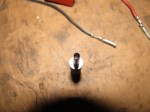
So we bought a new thermoswitch and swapped it in (this is not the time to tell what we found in the rad when we pulled old switch out) and everything worked as it should.
Note the erosion of the switch.
")
Theory time: we figure that when the van was sitting, the thermoswitch failed and allowed the second stage fan speed to come on. The brake booster vacuum line was worn and the battery drained. My friend’s wife must have heard it at the end of the battery life when the fan was slowly turning and making a clicking noise as it hit the brake booster vacuum line. This long run time caused the second stage relay to stick in the on position. Pulling the relay, the jiggling etc, caused the relay to open, and was then “under the control” of the thermoswitch, and again fuse #1.
Phew!
1987 US dealers Vanagon sales video
Bathe in the hyperbole…
Vanagon lighter socket
April 1, 2010… I edited the original post. I must have been all hepped up on goofballs first go round as I based the instructions on a bench disassembly rather than the “real life in front of the dash how the hell does this come out” situation. Apologies to all who may have been misled.
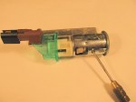
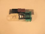
Quick post showing the Vanagon stock lighter. Its a little tricky to remove from dash when you want to replace it (I found that accessory plugs do not fit as tight as I wanted, especially the iPod dock on a stalk gadget I use).
Warning, disconnect electrical power before mucking around lighter! (either main battery cable or fuse #3 which serves to supply juice to door lights, radio, and lighter in ’86 and up vans).
Really, don’t do any of this with power supplied to lighter.
The lighter has a plastic plug electrical connector on back. Go ahead and remove that first, accessing from behind glove box (and yes, spill of all that stuff you have collected over the years when removing the glove box).
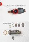
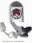
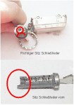
You can see the socket comprises of two parts; the illuminated green plastic ring, and the metal socket proper. The green ring has to be slid down the shaft of the socket first, or rather the metal body is slid out forward from dash. It is held in place by 2 tiny tabs that can be depressed from the inside of the socket. Once the metal body is out, the green ring can then be wiggled out of the dash, from the front, it can be tilted to get through hole.
In the pictures I have pointed out the slot in the metal socket that the green plastic tabs fit into. Its the slot beside the 2 elongated slots. Again, you depress the green plastic tabs from inside the socket and pull the metal socket forward and out.
I hope this helps, I know the assembly and fitment can be a bit puzzling first go round.


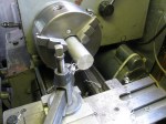
Making aluminium shavings
Posted by albell in metalworking on March 10, 2010
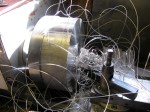
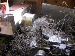
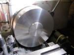
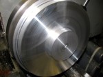
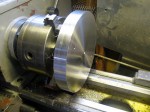
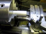
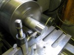
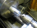
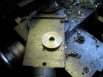
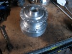
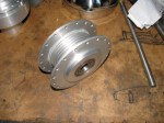
To make about 2/3 of a garbage bin of shavings, take a lump of 8″ aluminium round bar, and lathe away half of it over a cold afternoon in the workshop. What an inefficient way of doing things, but I ended up with a solid one piece flywheel for a non-vanagon project.
Note: I had to drill and tap two holes to bolt the stock to the faceplate, formed the “hub”, then could unbolt, flip it around and grab the hub in jawed chuck to finish other side. I feel compelled to say that I am by no means a machinist, just a home hobbyist.


Return of the escutcheon
Posted by albell in vanagon mods on March 8, 2010
I hear you ask, “when are you going to make a door handle escutcheon for a pre-86 Vanagon?”
Oh, get a life…
Those original style doors had longer handles (the door mechanism is so much more clunky than the ’86 and up models) and it seems a different style escutcheon. This time its hard plastic with a little tab that keys into a notch in door skin. So onward to the pictures… this is handle from my ’82 westy (the one pictured in the blog header.


lock info
Update, April 6 2010 : good info on this page on lock R&R, and in English!
lock rehab
Images found on a German Vanagon site, and I can’t recall the URL so forgive me for lack of attribution other than any text on images themselves.
Handy references for some lock work.


Multi-prong connector tool
Posted by albell in metalworking, tools, vanagon on February 28, 2010
Another trivial lathe job…
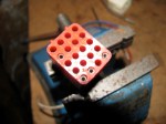
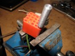
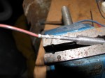
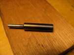
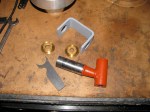
My ’86 Vanagon fuse box has multi-prong connectors in back. Some are spade, but most are the round prong variety, very similar to “Molex” brand. The individual metal connectors insert into the plastic blocks and are held in by “barbs” on the connector shaft. You can’t pull the connectors out of the block without damaging those barbs unless you have the special tool.
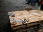
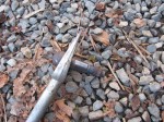
I made a couple of the tools for each size of connector. I used a large nail (spike) for stock and I have to admit to not really having confidence that the idea would work, so the you have to forgive me for choice of material and final finish. I am pretty sure there are commercial versions of this tool, better made and with a nicer finish.
As it turned out, the tools work perfectly well. You just insert the tool into the block, the barbs are pressed back into the body of the connector and the wire can be pulled out from the back of the block. The pictures below show the smaller sized tool. Jeez, I didn’t notice the rust on the little vice until I took the pictures. Winters on the west coast, damp and the workshop is not well sealed….


Update: Google “Molex pin remover” to see some nice and inexpensive commercial and home made versions.
Sliding door escutcheon
Posted by albell in metalworking, vanagon mods on February 14, 2010
The handle on the sliding door of Vanagons is secured only inside at the lock mechanism. At the outside door skin, the handle shaft passes through a rubber grommet “escutcheon”. This grommet does nothing to support the handle and is there only to prevent water ingress inside the door. The problem is that the forces applied when you use the handle puts a strain on the pot metal handle shaft and can, after some years, cause the shaft to break. I have seen an aftermarket replacement for sale on Ebay (link here) and it looks pretty good, made of black Delrin. I thought I would have a go at making something similar.
I had some
high density polyethylene
UHMW polyethylene rod
I thinks its actually teflon after buying some more UHMW and comparing… I feel dumb.
in the scrap bin and I chucked it up on the lathe and had at it. If I was smarter I would have just made it as a shouldered bushing, but I went to the trouble of making a groove to fit the door skin and then cutting the inner flange to allow it to press in place and remain secured. I don’t think you need to go to all that bother. Pictures below, you can see what I mean. The white poly does look a little daft, but hey its what I had lying around. It really makes a difference on how the handle feels when you use it, no looseness, it feels secure. Oh, also is one pic of the old stock rubber grommet.

Pop top conversion- Mosaik kit
Posted by albell in vanagon, vanagon mods on February 3, 2010
A neat way of doing it. Links below to UK Vanagon owners who have done it:
http://www.brick-yard.co.uk/forum/westy-poptop-fit_topic49144.html
http://www.brick-yard.co.uk/forum/topic30479.html
UK firm that makes the repro kit:
www.vwelevation.com
PDF of the original German install:
Mosaik-Joker_Aufstelldach
Gifs of the components:


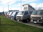
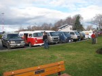
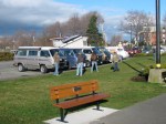
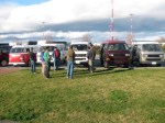
Victoria Vanagon meet
Last Sunday afternoon (February 1st), a few local Vanagon (and a couple of Loafs) owners gathered at Ogden Point. Here a a few snaps.


“G” and “M” connectors on ’86 fuse panel
I had to read the wiring diagrams when I installed the fog lights 🙂 The group of (mostly unused) spade connectors on back of panel have some interesting properties, especially G10. Here is what I decoded, your van’s panel may be different, but I hope this list will be useful in thinking about power taps.
The male spade connector group designated “G” in “that manual” trace out as follows:
G1 – X bus controlled power, fused through S12 (20A) (on my van it has BK/Y wire connected which feeds warm air blower switch)
G2 – #15 ignition switched power fused through S18 (10A)
G3 – X bus controlled power, fused through S12 (20A)
G4 – D+ alternator trigger circuit via alt. led light
G5 – #15 ignition switched power fused through S18 (10A)
G6 – dead end
G7 – power when headlights on
G8 – dimmer controlled dash light power
G9 – license plate lights power fused through S20 (10A)
G10 – power when windshield wipers run
and the M connections close by:
M1 – connected to G7
M2 – power with lowbeams
Fog/Aux. lights installed
Posted by albell in metalworking, vanagon mods on January 21, 2010
Finally finished the job. The bracket and light combo as originally designed did not allow the lights to point ahead without the backs hitting the lower grill. I put the aluminium spacers shown in previous post between the fog light and the right angle part of bracket. This pushed the light forward about 1/4″ providing enough clearance at the back.
I had planned on using the factory wiring set up (see German wiring diagram below) but have any of the pin type connectors (very much like Molex connectors) needed to plug into positions C22, B16, and B20 (multi prong connectors at back of fuse panel). But the surprising thing (well to me anyway) about the stock set up is that the additional relay added to “relay position 7” serves only to supply power to switch and not to isolate switch from the full light current. Just as it is a good thing to install relays in headlight system to reduce current load on headlight switch, I figure same approach should be taken with the aux. lights.
My version uses spade connectors and goes like this:
(this is for an ’86 syncro passenger van)
-G7 single point connector on back of fuse panel to + connector on switch *EDIT* I changed to use G3, X-relay power
-G9 single point connector on back of fuse panel to “30” on relay. G9 is fused through fuse # S20, license plate lights, I swapped in a 20 A fuse.
-connection from switch to “85” on relay.
-connection from light bulb on switch to ground.
-connection from “86” on relay to ground.
-connection from “87” on relay to fog light positive.
notes: the foglight switch is a 3 position switch and has 2 connectors on it, one for front fog light, one for rear fog light. It also has a light in it that illuminates when switch activated. The relay (40A) is mounted in one of those nifty bases that dovetails onto edge of fuse panel. G7 only has power when headlights are on *EDIT* I used the G3 spade, X-relay powered. so it gets power when ignition on. I grounded the lights via the right hand side lower radiator bracket bolt. The positive wire from lights passes through bumper sub frame via a grommeted hole, then up behind grill alongside the left hand edge of radiator then through body via a factory installed but unused grommet.
*EDIT* here is my circuit diagram as used

And here is the factory wiring.


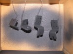
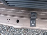
Fog/Aux. light brackets
Posted by albell in metalworking, vanagon mods on January 18, 2010
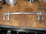
Been mucking around trying to make some fog light brackets. I’m following the factory method, somewhat. Bending 1/4″ stainless stock (by hand, using some heat) and using some aluminium angle. Stuff I had lying around. The Cibie lights I want to use are quite deep, so the install is not going as easily as I would have wanted. The pics in the gallery show a page from the German manual, a shot of a repro bracket made in the UK, and my efforts. I didn’t make the final bend on my bracket, I wanted to use the aluminium angle to give me a bit of adjustment room fore and aft. Also, I think the final bend makes the bracket more flexible. But the result was a light too close to the lower grill. So I needed to make some spacers, and take boring pictures of the lathe. The brackets are affixed to the frame below the bumper by plastic wall anchors for trial fitting, when I am happy with the fit I’ll use stainless bolts. Oh, and yes, I painted them with rattle can bed liner stuff. Lots of stupid pics of lathe work 🙂


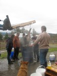
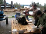
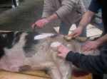
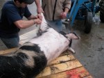
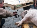
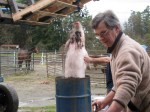
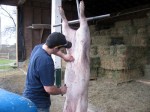
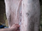
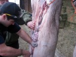
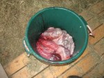
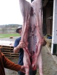
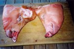
How we get pork
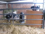
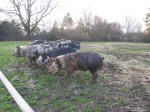
Last Sunday we slaughtered a pig. In the past we have taken pigs to a local abattoir/butcher, but changes to regulations have forced many small “artisan” butchers out of business. And this time we didn’t want to ship the pigs to a strange place, its a stressful thing for them. They are for our own consumption so we can do it on site, and we started with one yesterday.
A couple of friends came by to help, they had done same thing on their farm.
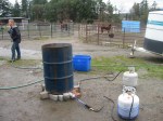
It went well, 410 shotgun with slug, in head, pig dropped immediately, no drama. It was bled via a cut at base of neck and down into aorta. Then we moved it to where we had a scalding bath set up (to loosen hair so it can be scrapped off).
The pictures are pretty self explanatory, but not for the faint of heart. After I post this I am off to make guanciale with the cheeks ( I didn’t take pics of the severed head, that’s a bit much).


Alternator info
Posted by albell in vanagon tech papers on January 6, 2010
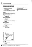
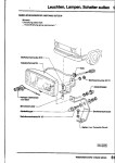
German language excerpt from manual showing exploded views and repair procedures for Vanagon alternators (45 – 90A models). It’s much more detailed than the equivalent sections in English language manual, plus you get a free German lesson.
alternator(G)
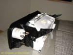
Frank G.’s modified instrument cluster
Posted by albell in vanagon mods on January 4, 2010
I took this from my website (http://www.members.shaw.ca/albell/) , thought some of you might be interested in it.
Frank writes:
Just finished building a new Vanagon Instrument cluster for my TDi conversion project. I’ve always disliked the Vanagon instrument pod. The center section really offended my sense of completeness. Just looked fake. When I decided to divert the 2.0 Turbo Audi project to the TDI, I decided to do something about it. The result combines the instrument cluster from the 1997 Passat TDI (contributes the gauge faces and front cluster face), a 1995 Passat GLs (contributes the MFA processor calibrated for the 4 cylinder engine), a vanagon cluster, the bezel from a ’97 Passat and a set of VDO gauges.
I’m using the wiper (controls the MFA) and turn signal stalks (controls the cruise control) on the steering column from the 1995 Passat GLS 4-cylinder. Here in the cluster, the temperature and fuel gauges are combined, with separate speedometer and tachometer. The warning light group contains the typical diesel functions. There are two unused light ports. I’m doing transfer logos for them and adding my two color (red/green) LED’s. One of the lights monitors the radiator fan speed (green for low, red for high). The other follows the auxiliary lights with green for Fog on and red for the driving lights. The MFA monitors among the standard features, the engine oil temperature, the average fuel consumption, the instantaneous fuel consumption and the external air temperature. This LCD screen also displays the digital clock.
In the bezel, I add a boost gauge and a pyrometer for EGT measurements. In the lower dash plane I have two gauges, one on either side of the column. To the left, oil pressure and to the right, oil temperature monitored after the oil coolers. In the lower heater face panel, I have a set of five gauges monitoring voltage on the primary circuit, voltage on the auxiliary battery circuit, the pressure in the radiator coolant circuit, an analog clock and an LED compass direction gauge.
The speedo drive is electronic. I took the rear mount out of an old Jetta speedo cluster I had, cut it up tp keep the frame and the Hall magnet wheel. Then mounted them in a box to take the place of the EGR counter. I use the 3 wire speedo hall sensor from the G/J series. Its a bolt up (or screw up) to the speedo frame. A variable pulse counter frequency adjuster (circuit supplied by my son) will allow variable adjustment for a dead on speedometer regardless of tires and state of wear. Precision wirewound pot for frequency conversion adjustment. Calibrate with simple GPS.
Further notes on fabrication…
On the master cylinder reservoir interference issue … it was in the way and I wanted to maintain the visual angles, so I took it out! I then used a master cylinder reservoir from a ’90’s Mazda pickup. It comes (from your local P&P yard) with a remote mounting bracket. I rotated it so the long axis is parallel to the windshield long axis. It comes with a built-in level sensor that I wired into the VW harness. I can’t remember if the vanagon originally came with the level sensor built in of if I added it to the vanagon reservoir and modded the harness years ago. For the inlet lines to master cylinder, I believe I used the plastic barb adaptors from a Super Beetle. I use an inline T to tap off the clutch feed. I mounted the reservoir in the same general area as the original Vanagon unit and aligned the inlet so that the plastic drip shield fit again (anal-retentive, I know). Clears the back of the cluster as if it were designed to do so! This solution should work for any cluster one would like to put in!
On the choice of cluster…. Well to start with, I have always thought (going back to March of ’82 when I placed the order for Westfalia for factory delivery) that the instrument cluster was a tacky design. The fake molded sensor lights particularly irritated me! I later years, I added the tach, the oil pressure warning circuits, the VSS speed sensor and redesigned the warning light package to give right and left turn signal lights, added cruise control lights, finally adding multicolor LEDs to the fake center section to monitor radiator fan speed, intercooler fan speeds, fog and driving lights and A/C control parameters. But I never liked the look of the thing.
When I decided to TDi the Vanagon, my orders to the salvage yard were that I wanted it all – engine, hoses, all wires and sensors. To my surprise, they included the speedometer cluster. The three gauge pattern carried the same info as the Vanagon cluster, but much more cleanly. The row of sensor lights along the bottom of the cluster was very tasteful and, the LCD display made it possible to add the MFA (multifunction display) to the package. I noticed immediately that the size of the Passat cluster was just a bit larger than the vanagon center section, so I decided it was time to generate a cluster that was good on the eyes and technically compatible with the Vanagon. The MFA was a key part of the equation, since I could integrate a miles per gallon function together with monitors for oil temperature and all OBD II sensed engine variables (the son is hacking the MFA controller to display all VAG.com accessible info). So, while the A4 cluster is nice and the later sport clusters from the Passat and G/J series are very impressive, they were somehow not in the same design paradigm as the classic Vanagon shape. The approach I used is compatible with any cluster. I chose not to go the digital monitor approach or to rebuild with aftermarket gauges (VDO or other), although the 9 gauge custom cluster seen here on the list recently pushed me from design to implementation.
Key details … Needed – Dremel tool, JB Weld, ’97 Passat instrument bezel, ’95 to ’97 Passat instrument cluster, one or more Vanagon instrument cluster bezels, flexible bumper spray paint, 20+ hours, high quality source of KMZT-FMin garage. To begin, I cut away all the instrument pod from the plastic vanagon bezel to a distance of about 1 inch from the front face. I cut off the bezel support pieces so I could reassemble them to the cluster in the end. I then took the plastic ’97 instrument bezel and used it to shape the remaining vanagon bezel surface. When I has the shape right (easier than it sounds with the Dremel tool) I bonded the passat bezel to the vanagon plastic. This left a series of open areas since the smooth transitions at the top and sides were not a part of the Vanagon shape. These areas were filled with JB Weld then smoothed and shaped by hand with various wet/dry sanding papers. On the back side of the Vanagon cluster, I removed the plastic shell support for everything except for the light switch and the lowest switch position on the right. I then filled and smoothed the front surface in preparation for cutting the two 2 1/16 gauges that I wanted as part of the cluster. I then bonded the cluster support pi eces from the original vanagon bezel to the revised unit. I set the positions in a jig, heat treated the plastic for a slightly different takeoff angel to meet the original mount point without stress. These support pieces were about 0.250 inches further to the right and left than the original. I then fitted the Passat cluster (took off some interfering tabs) and reinforced the remaining structure with JB Weld. The gauge holes and switch areas were then clearanced and a final sanding polish performed before painting with the flexible semi-gloss black. The paint removed fine sanding damage with a high film strength drying surface. Did a test fit and all was well including the latched top pod cover.
On the instrument cluster mods … I added the boost (0-30 psi) and EGT gauges in an excellent 270 degree sweep unit made by Speedhut. The MFA cluster (not part of the original Passat TDi cluster) was pieced together from a ’95 Passat GLs (4 cylinder motor) cluster with turn signal (has cruise control switch) and wiper (has MFA controller) stalks from same. (This idea came from Chris Bell on the TDIClub list). The tach sensing was correct for the TDi engine. The temperature gauge is appropriate for the sensor on the engine. The gas gauge worked for full scale to empty due to VW internal standardization policy! The speedo sensor is electronic. I cut up a GTi speedo cluster to get the Hall effect sensor wheel and mount shell. Added a VW three wire VSS sensor and turned it all into a 2.0 x 2.0 x 1.5 inch adaptor that pops onto the end of the Vanagon speedometer cable. I convert the pulses from this Hall sensor packet to the frequency (pulses per mile) needed by the Passat cluster with either a Dakota Digital pulse frequency converter of a circuit for variable calibration designed by my son. In the custom circuit, we would calibrate the speedometer with a GPS system and thereby lock it on for any tire combination.


67 BSA Thunderbolt
Posted here just because it looks good, and pic was taken summer (2004) reminding me that the driveway does dry out.

Nice syncro
I found this series of pics on my computer. I don’t recall where I originally got them from, if anyone recognises them I’d appreciate getting the info for attribution.
Lots of nice touches, one thing especially is the raised instrument cluster which I think would allow a better view of the dials.


VC paper
Posted by albell in vanagon tech papers on December 10, 2009
required reading…if you can find it, WordPress seems to be baulky. Fixed now.
VC research paper, 1986
Webasto BBW 46 heater
Posted by albell in syncro specific repairs on December 8, 2009
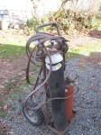
My ’86 syncro has a Webasto BBW 46 coolant heater, but unfortunately it has been disconnected from the coolant system and does not work. Why was it disconnected? I don’t know, so here starts another syncro adventure.
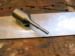
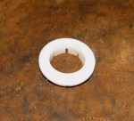
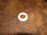
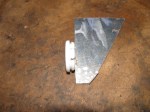
The heater is quite cool, has a control unit that will start the heater up at pre-set times, it burns gasoline to heat and circulate the coolant, and also turns on the cabin heater fan, thus warming the engine and the cabin. But it seems a fairly complicated affair to troubleshoot…
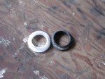
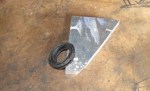
One thing I did discover is that the small, lipped, sealing ring between the heat exchanger and the recirculation pump has failed, maybe that is why it was disconnected? Local marine repair shop is hung down a replacement for me.
But I have heard that the unit really needs to be used regularly, this one obviously has not been used in a while, so even if I get the seal installed there is no guarantee the heater will work.
I’ll take some pics tomorrow.
Resources:
Gary Lee has one installed in his van, and link to repair manual (but its not a vanagon specific manual, and the vanagon install does have its own “qualities”)
webasto in vanagon, in German, again…
parts manual:70966B
Dec 9, evening, slapping unlabelled pics up:
Ball joint shenanigans
Posted by albell in syncro specific repairs on December 2, 2009
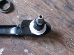
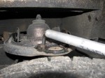
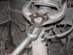
Over the last week or so I started hearing a slight knocking/clicking intermittent noise from front right of van. I had a look under van yesterday and found I could produce the noise if i bounced the front of the van. I narrowed it down to the upper ball joint by levering upper A-arm with pry bar (see pic), the joint would move and make the noise.
So today I set about replacing the joint. I looked at the manual and at Tom Forhan’s excellent description, bought a nice German ball joint, looked forward to one of those satisfying and straightforward repairs.
Oh, I did spray penetrating oil on the joint the night before, and also I heeded the warning on the ball joint box not to do this naked but rather wear overalls, a hat, and carry a huge wrench.
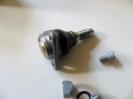
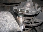
All went according to Tom’s instructions until I tried to “pop” the joint out. No way would it budge. Ideally what happens is that you drive the pickle fork in then strike the side of the assembly the joint goes into. On the syncro there is a suitable flat on the aft edge of the steering knuckle. I was using a 4 lb hand sledge. I ended up destroying the socket part of the joint leaving the ball part firmly in the steering knuckle. Believe me, I whacked that bugger a lot.
This was the time in these kind of jobs where the calm demeanour turns into hatred of mechanical things. Time to get the torch. I didn’t really want to heat up the knuckle, I thought that heating the ball then pouring water on it would break whatever unholy bond had been formed. Nope, still no luck. Finally broke down and “gently’ heated the upper portion of the knuckle, not red hot mind you, and then the pickle fork would drive the bugger off.
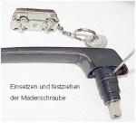
Installation of the new joint was simple (and slathered in anti-seize), apart from the fact that you have to hold the end of the threaded shaft (12 mm wrench) from turning as you tighten up the nylocked nut. Only closed ended 15/16” wrench (my 24 mm substitute) would fit and even then only allowed a few degrees of turning, grrr.
All this took 4 hours, including a few calming down breaks.
I’ve included a pic of my “Jack-All” high lift type jack with my home made adapter that fits in the vanagon jacking points.


Shilling for Meguires
Was asked to treat the ’80’s style floor mats with the same stuff I used on the full front mat. Marvel at the before and after pics.


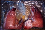
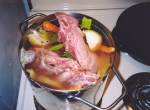
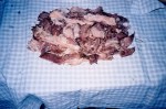
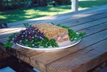
Headcheese (brawn)
Looking at the pigs today reminded me of the time back in 2004 when I made headcheese from one of the pigs raised on the property. They weren’t “old breed” pigs, just the regular old commercial variety. Anyway, I had the butcher set aside one head for me. It came, de-brained and split, in a vacuum pack. Funny thing was one half seemed a little roughed up. I consulted a few old books and I set about making brawn. The pictures tell the story. I don’t like headcheese, but it wasn’t that bad, good sliced on a sandwich.


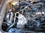
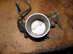
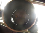
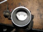
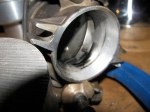
2.1 l wasserboxer throttle body
Old throttle body from my spare 2.1 l engine. Note the “cut out” on butterfly plate.


Cyclekart
Posted by albell in cyclekart, metalworking on November 29, 2009
I am making a cyclekart for my son, thought I’d start posting pics. For more information on cyclekarts, see here.
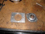
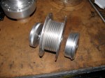
Hubs are Motobecane moped hubs, I took the spokes off and machined them a bit. One front hub is shown, with machined bearing housings. The rear fixed hub is shown, its the one with the overbuilt hub adapter. Lots of aluminium shavings when I did that one.
I’ll add more text explaining the parts later.

November 29, sunny afternoon
Three days now without heavy rain.


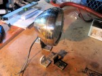
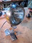
Cibie aux. light
Posted by albell in vanagon mods on November 29, 2009
Another auto wrecker find, from a JDM Pajero or Montero (can’t recall). I thinks its a Japanese market SC Oscar, its stainless with H1 bulb. I got the pair. I don’t know yet whether they are wide or narrow beam. The reason I post them here is that the housings are tantalizingly close to fitting the Iltis H4 headlights.


